

MTD 341, 342, 343, 344 Operator's Manual

Operator's Manual
Front Tine Tillers
Model Series
340 Thru 390
Model Series 390 Shown
IMPORTANT: READ SAFETY RULES AND INSTRUCTIONS CAREFULLY
Warning: This unit is equipped with an internal combustion engine and should not be used on or near any unimproved forest-
covered, brush-covered or grass-covered land unless the engine's exhaust system is equipped with a spark arrester meeting
applicable local or state laws (if any), If a spark arrester is used, it should be maintained in effective working order by the operator,
In the State of California the above is required by law (Section 4442 of the California Public Resources Code), Other states may have
similar laws, Federal laws apply on federal lands, A spark arrester for the muffler is available through your nearest engine authorized
service dealer or contact the service department, P,O, Box 361131 Cleveland, Ohio 44136-0019,
MTD LLC, P.O. BOX 361131 CLEVELAND, OHIO 44136-0019
PRINTED IN U.S.A. FORM NO. 770-10135E
(10/05)
TABLEOFCONTENTS
Content
Important Safe Operation Practices
Assembling Your Tiller
Know Your Tiller
Operating Your Tiller
Making Adjustments
Page Content
3 Maintaining Your Tiller
5 Troubleshooting
7 Illustrated Parts List
8 Warranty
11
FINDINGMODELNUMBER
This Operator's Manual is an important part of your new tiller. It will help you assemble, prepare and
maintain the unit for best performance. Please read and understand what it says.
Before you start assembling your new equipment, please locate the model plate on the
equipment and copy the information from it in the space provided below. A sample model plate is
also given below. You can locate the model plate by standing at the operating position and
looking down at the right side of the frame. This information will be necessary to use the
manufacturer's web site and/or help from the Customer Support Department or an authorized
service dealer.
Copy the model number here:
_)ff M*DLLC
k www.mLuprouucLs,com_-'--' _ 880-888-731 O ,
P. O. BOX 361131
CLEVELAND,OH 44136
338-228-4683
Copy the serial number here:
Page
11
14
16
24
CUSTOMERSUPPORT
Please doNOTreturntheunittotheretailerfromwhereit waspurchased,withoutfirstcontactingCustomerSupport.
If you have difficulty assembling this product or have any questions regarding the controls, operation or
maintenance of this unit, you can seek help from the experts. Choose from the options below:
Visit mtdproducts.com for many useful suggestions. Click on Customer Support button and
you will get the four options reproduced here. Click on the appropriate button and help is
immediately available.
8nswer you 8__
_ mouse click _w_/
If you prefer to reach a Customer Support Representative, please call 1-800-800-7310.
_nswer you __
looking for could be just
_ mouse click _w_y!
M nual
The engine manufacturer is responsible for all engine-related issues with regards to
performance, power-rating, specifications, warranty and service. Please refer to the engine
En ine
manufacturer's Owner's/Operator's Manual, packed separately with your unit, for more
information.
SECTION1: IMPORTANTSAFEOPERATIONPRACTICES
WARNING: This symbol points out important safety instructions which, if not followed, could endanger
the personal safety and/or property of yourself and others. Read and follow all instructions in this
manual before attempting to operate this machine. Failure to comply with these instructions may result
in personal injury. When you see this symbol-- heed its warning.
WARNING: Engine exhaust, some of its constituents, and certain vehicle components contain or emit
chemicals known to State of California to cause cancer and birth defects or other reproductive harm.
DANGER: This machine was built to be operated according to the rules for safe operation in this
manual. As with any type of power equipment, carelessness or error on the part of the operator can
result in serious injury. This machine is capable of amputating hands and feet. Failure to observe the
following safety instructions could result in serious injury or death.
Training
1. Read, understand, and follow all instructions on the
machine and in the manual(s) before attempting to
assemble and operate. Keep this manual in a safe
place for future and regular reference and for
ordering replacement parts.
2. Be familiar with all controls and their proper
operation. Know how to stop the machine and
disengage them quickly.
3. Never allow children under 14 years old to operate
this machine. Children 14 years old and over should
read and understand the operation instructions and
safety rules in this manual and should be trained
and supervised by a parent.
4. Never allow adults to operate this machine without
proper instruction.
5. Keep bystanders, helpers, pets and children at least
75 feet from the machine while it is in operation.
Stop machine if anyone enters the area.
Preparation
1. Thoroughly inspect the area where the equipment is
to be used. Remove all stones, sticks, wire, and
other foreign objects which could be tripped over
and cause personal injury.
2. Wear sturdy, rough-soled work shoes and close
fitting slacks and shirt. Loose fitting clothes or
jewelry can be caught in movable parts. Never
operate this machine in bare feet or sandals.
3. Disengage clutch levers and shift (if provided) into
neutral ("N") before starting the engine.
4. Never leave this machine unattended with the
engine running.
5. Never attempt to make any adjustments while
engine is running, except where specifically
recommended in the operator's manual.
6. To avoid personal injury or property damage use
extreme care in handling gasoline. Gasoline is
extremely flammable and the vapors are explosive.
Serious personal injury can occur when gasoline is
spilled on yourself or your clothes which can ignite.
Wash your skin and change clothes immediately.
7. Use only an approved gasoline container.
8. Extinguish all cigarettes, cigars, pipes and other
sources of ignition.
9. Never fuel machine indoors.
10. Never remove gas cap or add fuel while the engine
is hot or running.
11. Allow engine to cool at least two minutes before
refueling.
12. Never over fill fuel tank. Fill tank to no more than Y2
inch below bottom of filler neck to provide space for
fuel expansion.
13. Replace gasoline cap and tighten securely.
14. If gasoline is spilled, wipe it off the engine and
equipment. Move machine to another area. Wait 5
minutes before starting the engine.
15. Never store the machine or fuel container inside
near an open flame, spark or pilot light (e.g.
furnace, water or space heater, clothes dryer etc.).
16. Allow machine to cool 5 minutes before storing.
Operation
1. Do not put hands or feet near rotating parts. Contact
with the rotating parts can amputate hands and feet.
2. Do not operate machine while under the influence
of alcohol or drugs.
3. Never operate this machine without good visibility
or light. Always be sure of your footing and keep a
firm hold on the handles.
4. Keep bystanders, helpers, pets, and children at
least 75 feet from the machine while it is in
operation. Stop the machine if anyone enters the
area.
5. Be careful when tilling in hard ground. The tines
may catch in the ground and propel the tiller
forward. If this occurs, let go of the handle bars and
do not restrain the machine.
6. Exercise extreme caution when operating on or
crossing gravel surfaces. Stay alert for hidden
hazards or traffic. Do not carry passengers.
7. Never operate the machine at high transport
speeds on hard or slippery surfaces.
8. Exercise caution to avoid slipping or falling.
9. Lookdownandbehindandusecarewhenin
reverseorpullingmachinetowardsyou.
10. Starttheengineaccordingtotheinstructionsfound
inthismanualandkeepfeetwellawayfromthe
tinesatalltimes.
11. Afterstrikingaforeignobject,stoptheengine,
disconnectthesparkplugwireandgroundagainst
theengine.Thoroughlyinspectthemachineforany
damage.Repairthedamagebeforestartingand
operating.
12. Disengageallclutchleversandstopenginebefore
youleavetheoperatingposition(behindthe
handles).Waituntilthetinescometoacomplete
stopbeforeuncloggingthetines,makingany
adjustments,orinspections.
13. Neverrunanengineindoorsorinapoorly
ventilatedarea.Engineexhaustcontainscarbon
monoxide,anodorlessanddeadlygas.
14. Mufflerandenginebecomehotandcancausea
burn.Donottouch.
15. Usecautionwhentillingnearfences,buildingsand
undergroundutilities.Rotatingtinescancause
propertydamageorpersonalinjury.
16. Donotoverloadmachinecapacitybyattemptingto
tillsoiltodeepattofastofarate.
17. Ifthemachineshouldstartmakinganunusualnoise
orvibration,stoptheengine,disconnectthespark
plugwireandgrounditagainsttheengine.Inspect
thoroughlyfordamage.Repairanydamagebefore
startingandoperating.
18. Keepallshields,guardsandsafetydevicesinplace
andoperatingproperly.
19. Neverpickuporcarrymachinewhiletheengineis
running.
20. Useonlyattachmentsandaccessoriesapprovedby
themanufacturer.Failuretodoso,canresultin
personalinjury.
21. Ifsituationsoccurwhicharenotcoveredinthis
manual,usecareandgoodjudgment.Contactyour
dealerortelephone1-800-800-7310forassistance
andthenameofyournearestservicingdealer.
Maintenance&Storage
1. Never tamper with safety devices. Check their
proper operation regularly.
2. Check bolts and screws for proper tightness at
frequent intervals to keep the machine in safe
working condition. Also, visually inspect machine for
any damage.
3. Before cleaning, repairing, or inspecting, stop the
engine and make certain the tines and all moving
parts have stopped. Disconnect the spark plug wire
and ground it against the engine to prevent
unintended starting.
4,
Do not change the engine governor settings or
over-speed the engine. The governor controls the
maximum safe operating speed of the engine.
5,
Maintain or replace safety and instruction labels, as
necessary.
6.
Follow this manual for safe loading, unloading,
transporting, and storage of this machine.
7.
Never store the machine or fuel container inside
where there is an open flame, spark or pilot light
such as a water heater, furnace, clothes dryer etc.
8,
Always refer to the operator's manual for proper
instructions on off-season storage.
9.
If the fuel tank has to be drained, do this outdoors.
10.
Observe proper disposal laws and regulations for
gas, oil, etc. to protect the environment.
YourResponsibility
1. Restrict the use of this power machine to persons
who read, understand and follow the warnings and
instructions in this manual and on the machine.
2. The safety label on the tiller is reproduced below for
your review. To ensure safe operation of the tiller,
follow the instructions on all labels closely.
TO AVOID SERIOUS INJURY
READTHE_ERATOR'SMANUAL,
KNOWLOCATIONANDFUNCTIONS
OFALLCONTROLS.
KEEPALLSAFETYDEVICESAND
SHIELDSINPLACEANDWORKI_,
NEVERALLOWCHILDRENOR
UNINSTRUCTEDADULTSTO
OPERATETILLER,
SHUTOFFENGINEBEFORE
UNCLOGGI_TINESORMAKING
REPAIRS,
KEEPBYSTANDERSAWAYFROM
MACHINE,
KEEPAWAYFROMROTATING
PART&
USEEXTREMECAUTIONWHEN
REVERSINGORPULLINGTHE
MACHINETOWARDSYOU_
SECTION2: ASSEMBLINGYOURTILLER
NOTE: This operator's guide covers three different
model tillers. Model series 340 thru 345 have forward
tine drive only. Model series 390 has both forward and
reverse tine drive. Follow only the instructions which
pertain to your model tiller. See the model plate on your
tiller for the correct model number.
NOTE: References to right or left side of the tiller are
determined from behind the unit in the operating
position.
RemovingUnitFromCarton
• Remove staples, break glue on top flaps, or cut
tape at carton end and peel along top flap to open
carton.
• Remove all loose parts included with unit (i.e.,
operator's manual, etc.)
• Cut corners and lay carton down flat.
• Remove packing material.
• Roll or slide unit out of carton. Check carton
thoroughly for loose parts.
• Extend control cable(s) to the rear of the tiller and
lay them on the floor. Be careful not to bend or kink
control cable(s).
IMPORTANT:This unit is shipped without gasoline or oil
in the engine. Be certain to service engine with gasoline
and oil as instructed in the separate engine manual
before operating your machine.
BeforeAssembly
and ground it against the engine to prevent
WARNING: Disconnect the spark plug wire
unintended starting.
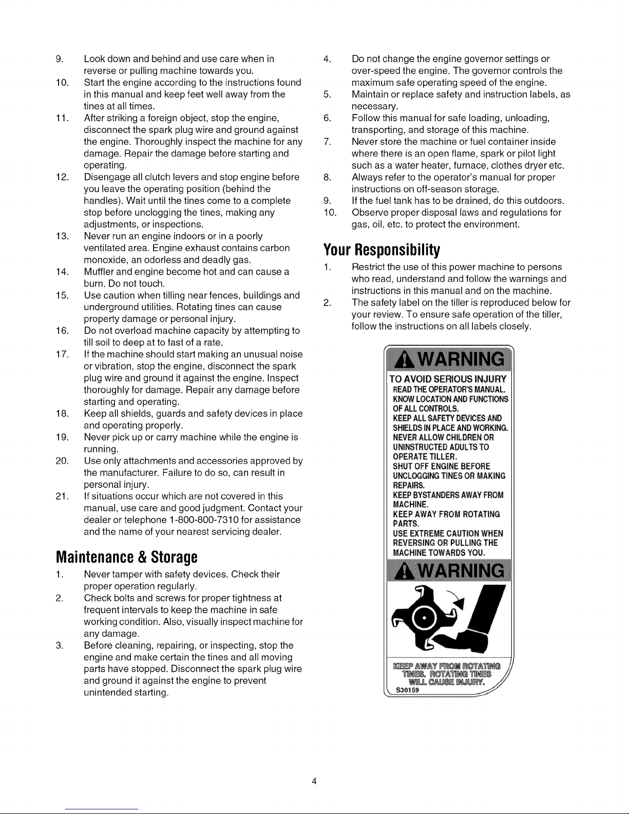
AttachingTailpieceAndDepthStake
NOTE: If your tiller's tailpiece and depth stake has
been already assembled before shipping, proceed to
the next section. If it is unassembled, follow the steps
below.
Remove the two self-tapping screws on the frame.
Slide the tailpiece into the frame with the lower hole in
the tailpiece toward the front. Secure with screws just
removed. See Figure 1.
Depth
Stake
Screws
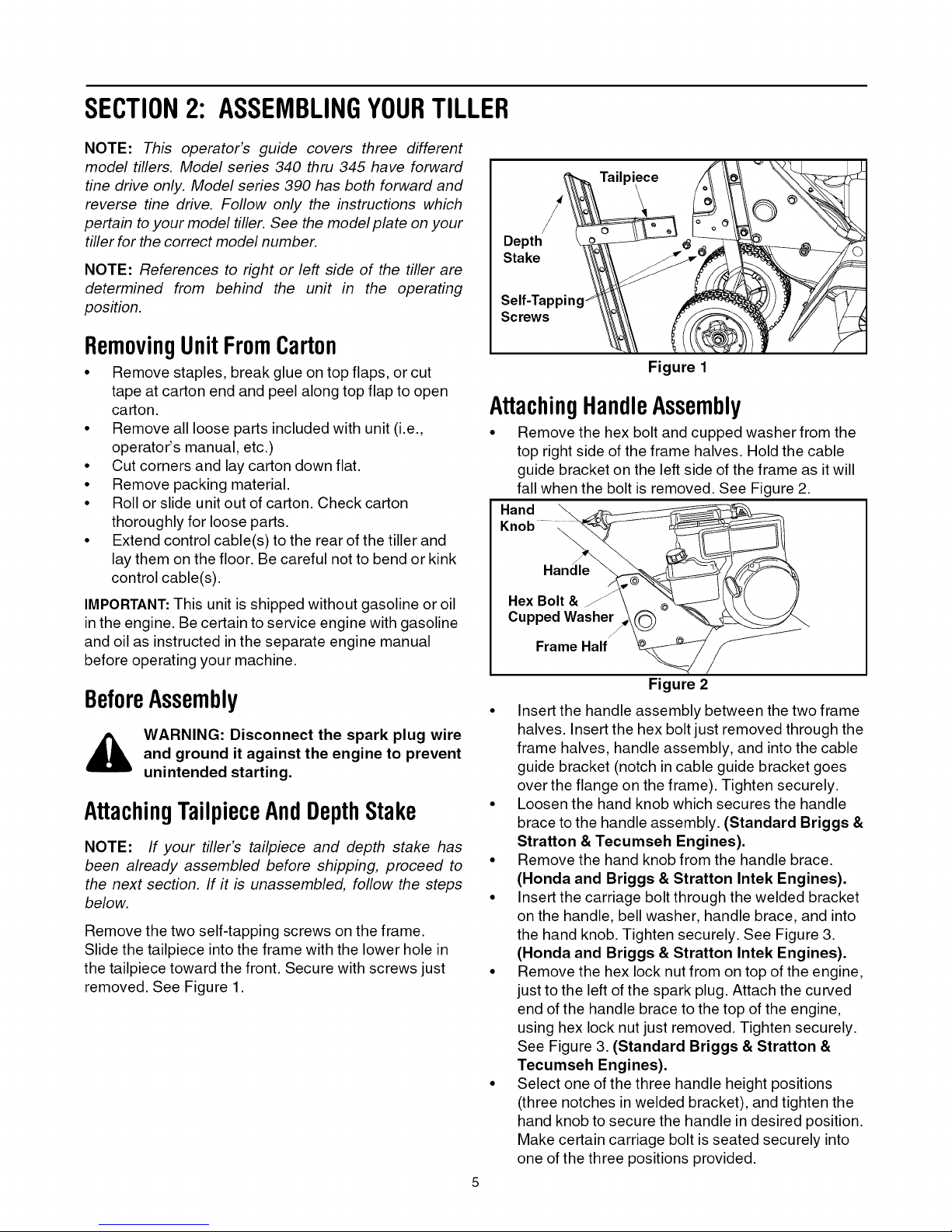
AttachingHandleAssembly
• Remove the hex bolt and cupped washer from the
Hand __
Knob....
• Insert the handle assembly between the two frame
• Loosen the hand knob which secures the handle
• Remove the hand knob from the handle brace.
• Insert the carriage bolt through the welded bracket
• Remove the hex lock nut from on top of the engine,
• Select one of the three handle height positions
)iece
Figure 1
top right side of the frame halves. Hold the cable
guide bracket on the left side of the frame as it will
fall when the bolt is removed. See Figure 2.
Ha_
HexBolt&F \ _ _
Cupped Washer _\_
FrameHa'ff_'_
Figure 2
halves. Insert the hex bolt just removed through the
frame halves, handle assembly, and into the cable
guide bracket (notch in cable guide bracket goes
over the flange on the frame). Tighten securely.
brace to the handle assembly. (Standard Briggs &
Stratton & Tecumseh Engines).
(Honda and Briggs & Stratton Intek Engines).
on the handle, bell washer, handle brace, and into
the hand knob. Tighten securely. See Figure 3.
(Honda and Briggs & Stratton Intek Engines).
just to the left of the spark plug. Attach the curved
end of the handle brace to the top of the engine,
using hex lock nut just removed. Tighten securely.
See Figure 3. (Standard Briggs & Stratton &
Tecumseh Engines).
(three notches in welded bracket), and tighten the
hand knob to secure the handle in desired position.
Make certain carriage bolt is seated securely into
one of the three positions provided.
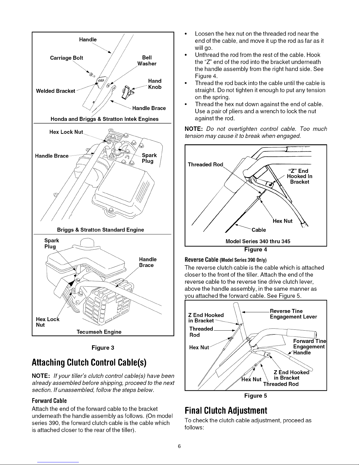
Handle
/
Carriage Bolt Bell
\-. Washer
\
Hand
Welded __ Knob
_""_ Handle Brace
Honda and Briggs & Stratton Intek Engines
Hex Lock Nut
Handle
• Loosenthe hex nut on the threaded rod near the
end of the cable, and move it up the rod as far as it
will go.
• Unthread the rod from the rest of the cable. Hook
the "Z" end of the rod into the bracket underneath
the handle assembly from the right hand side. See
Figure 4.
• Thread the rod back into the cable until the cable is
straight. Do not tighten it enough to put any tension
on the spring.
• Thread the hex nut down against the end of cable.
Use a pair of pliers and a wrench to lock the nut
against the rod.
NOTE: Do not overtighten control cable. Too much
tension may cause it to break when engaged.
Threaded Rod
"Z" End
Hooked In
Bracket
Briggs & Stratton Standard Engine
Spark
Plug
Handle
Brace
Hex Lock
Nut
Tecumseh Engine
Figure 3
AttachingClutchControlCable(s)
NOTE: If your tiller's clutch control cable(s) have been
already assembled before shipping, proceed to the next
section. If unassembled, follow the steps below.
ForwardCable
Attach the end of the forward cable to the bracket
underneath the handle assembly as follows. (On model
series 390, the forward clutch cable is the cable which
is attached closer to the rear of the tiller).
Hex Nut
Cable
Model Series 340 thru 345
Figure 4
ReverseCable(ModelSeries300Only)
The reverse clutch cable is the cable which is attached
closer to the front of the tiller. Attach the end of the
reverse cable to the reverse tine drive clutch lever,
above the handle assembly, in the same manner as
'ou attached the forward cable. See Figure 5.
Reverse Tine
Z End Hooked Engagement Lever
in
Rod
Forward Tine
Hex Engagement
in Bracket
Rod
Figure 5
FinalClutchAdjustment
To check the clutch cable adjustment, proceed as
follows:
• Disconnectthesparkplugwireandmoveitaway
fromthesparkplugtopreventaccidentalstarting.
• Engageandreleasethetineengagementhandle,
thenthereversetineengagementlever(model
series390only).Ifanexcessivenoiseisheard
whenreleasingeitherthetinedriveclutchhandleor
lever,thecablemaybetooloose.Adjusteitherthe
forwardorreverseclutchcablebylooseningthe
hexnut,threadingtherodintothecableoneortwo
turns,thenretighteningthenut.
• Withtineengagementhandleinneutral(released)
asshowninFigure6,pullthestarterropeseveral
times.Thetinesshouldnotturn.Iftheyturn
forward,loosenthehexnutontheforwardcable
(underneaththehandleassembly).Iftheyturn
towardtherear(modelseries390only),loosenthe
hexnutonthereversecable(abovethehandle
SECTION3: KNOWYOURTILLER
all instructions and warnings on the
WARNING: Read, understand, and follow
machine and in this manual before
operating.
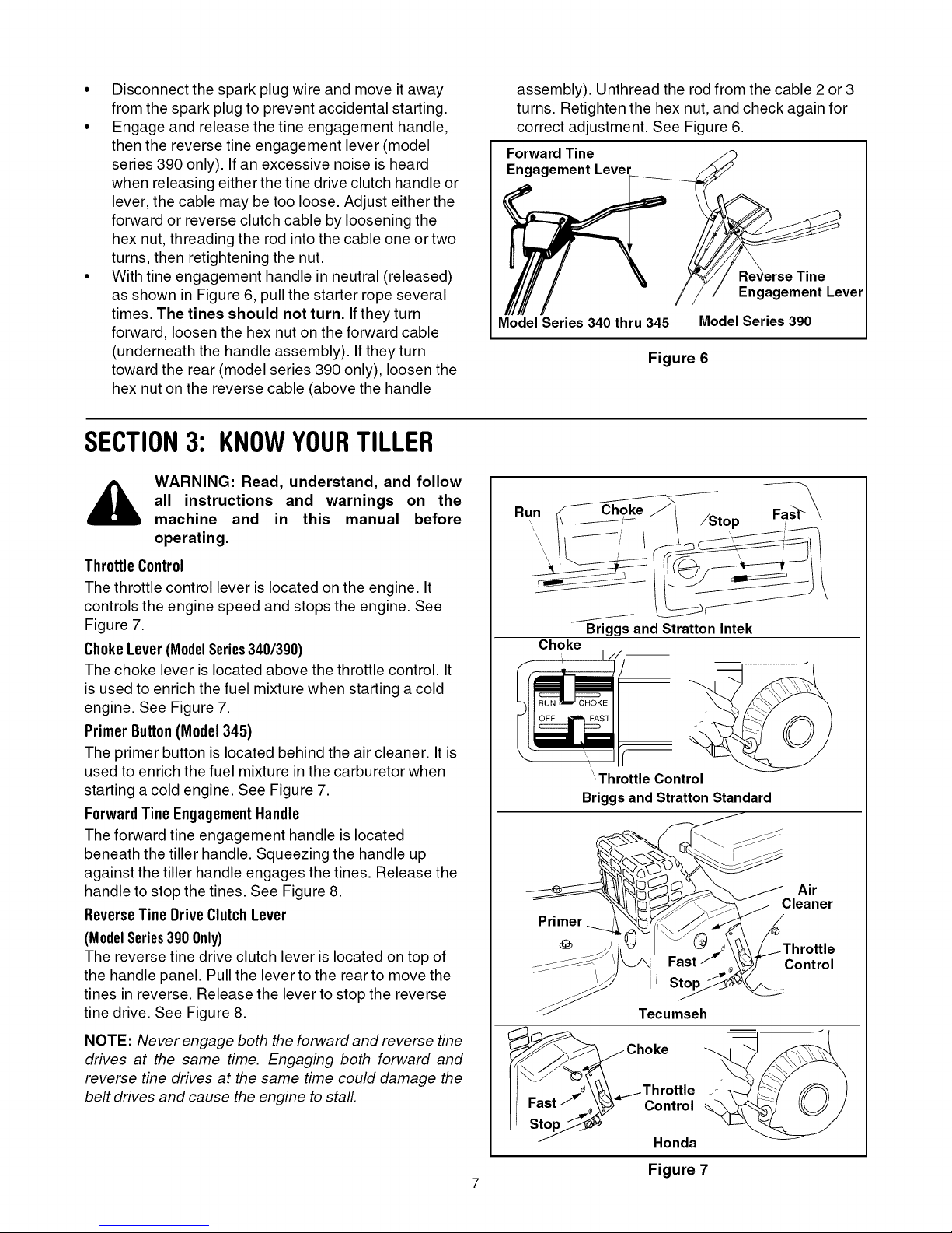
ThrottleControl
The throttle control lever is located on the engine. It
controls the engine speed and stops the engine. See
Figure 7.
ChokeLever (ModelSeries340/390)
The choke lever is located above the throttle control. It
is used to enrich the fuel mixture when starting a cold
engine. See Figure 7.
PrimerButton(Model345)
The primer button is located behind the air cleaner. It is
used to enrich the fuel mixture in the carburetor when
starting a cold engine. See Figure 7.
ForwardTine EngagementHandle
The forward tine engagement handle is located
beneath the tiller handle. Squeezing the handle up
against the tiller handle engages the tines. Release the
handle to stop the tines. See Figure 8.
ReverseTineDriveClutchLever
(ModelSeries390 0nly)
The reverse tine drive clutch lever is located on top of
the handle panel. Pullthe lever to the rear to move the
tines in reverse. Release the lever to stop the reverse
tine drive. See Figure 8.
assembly).Unthreadtherodfromthecable2or3
turns.Retightenthehexnut,andcheckagainfor
correctadjustment.SeeFigure6.
Forward Tine
Engagement Lever
Engagement Lever
Model Series 340 thru 345
Figure 6
Run
Briggsand Stratton Intek
Choke
....Throttle Control
Briggsand Stratton Standard
Primer
Model Series 390
Air
Cleaner
Control
NOTE: Never engage both the forward and reverse tine
drives at the same time. Engaging both forward and
reverse tine drives at the same time could damage the
belt drives and cause the engine to stall.
7
Figure 7
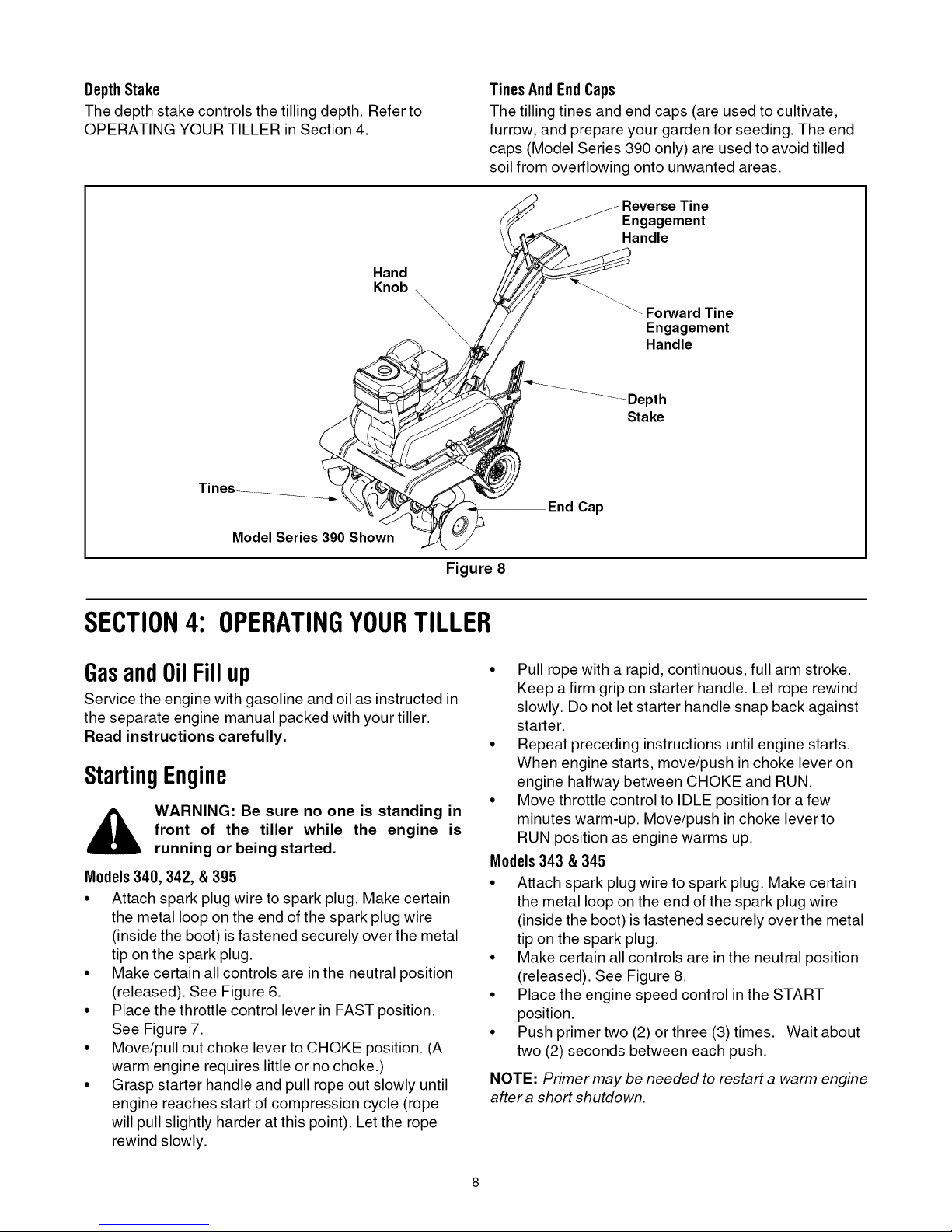
DepthStake
The depth stake controls the tilling depth. Refer to
OPERATING YOUR TILLER in Section 4.
Hand
Knob
Model Series 390 Shown
TinesAndEndCaps
The tillingtines and end caps (are used to cultivate,
furrow, and prepare your garden for seeding. The end
caps (Model Series 390 only) are used to avoid tilled
soil from overflowing onto unwanted areas.
Engagement
Handle
\
\
\
\
\
--Forward Tine
Engagement
Handle
Depth
Stake
End Cap
Figure 8
SECTION4: OPERATINGYOURTILLER
GasandOilFillup
Service the engine with gasoline and oil as instructed in
the separate engine manual packed with your tiller.
Read instructions carefully.
StartingEngine
,_ WARNING: Be sure no one is standing in
Models340, 342, & 395
• Attach spark plug wire to spark plug. Make certain
• Make certain all controls are in the neutral position
• Place the throttle control lever in FAST position.
• Move/pull out choke lever to CHOKE position. (A
• Grasp starter handle and pull rope out slowly until
front of the tiller while the engine is
running or being started.
the metal loop on the end of the spark plug wire
(inside the boot) is fastened securely over the metal
tip on the spark plug.
(released). See Figure 6.
See Figure 7.
warm engine requires little or no choke.)
engine reaches start of compression cycle (rope
will pull slightly harder at this point). Let the rope
rewind slowly.
• Pull rope with a rapid, continuous, full arm stroke.
Keep a firm grip on starter handle. Let rope rewind
slowly. Do not let starter handle snap back against
starter.
• Repeat preceding instructions until engine starts.
When engine starts, move/push in choke lever on
engine halfway between CHOKE and RUN.
• Move throttle control to IDLE position for a few
minutes warm-up. Move/push in choke lever to
RUN position as engine warms up.
Models343 & 345
• Attach spark plug wire to spark plug. Make certain
the metal loop on the end of the spark plug wire
(inside the boot) isfastened securely over the metal
tip on the spark plug.
• Make certain all controls are in the neutral position
(released). See Figure 8.
• Place the engine speed control in the START
position.
• Push primer two (2) or three (3) times. Wait about
two (2) seconds between each push.
NOTE: Primer may be needed to restart a warm engine
after a short shutdown.
 Loading...