

MTD 31B-611D062 Owner’s Manual
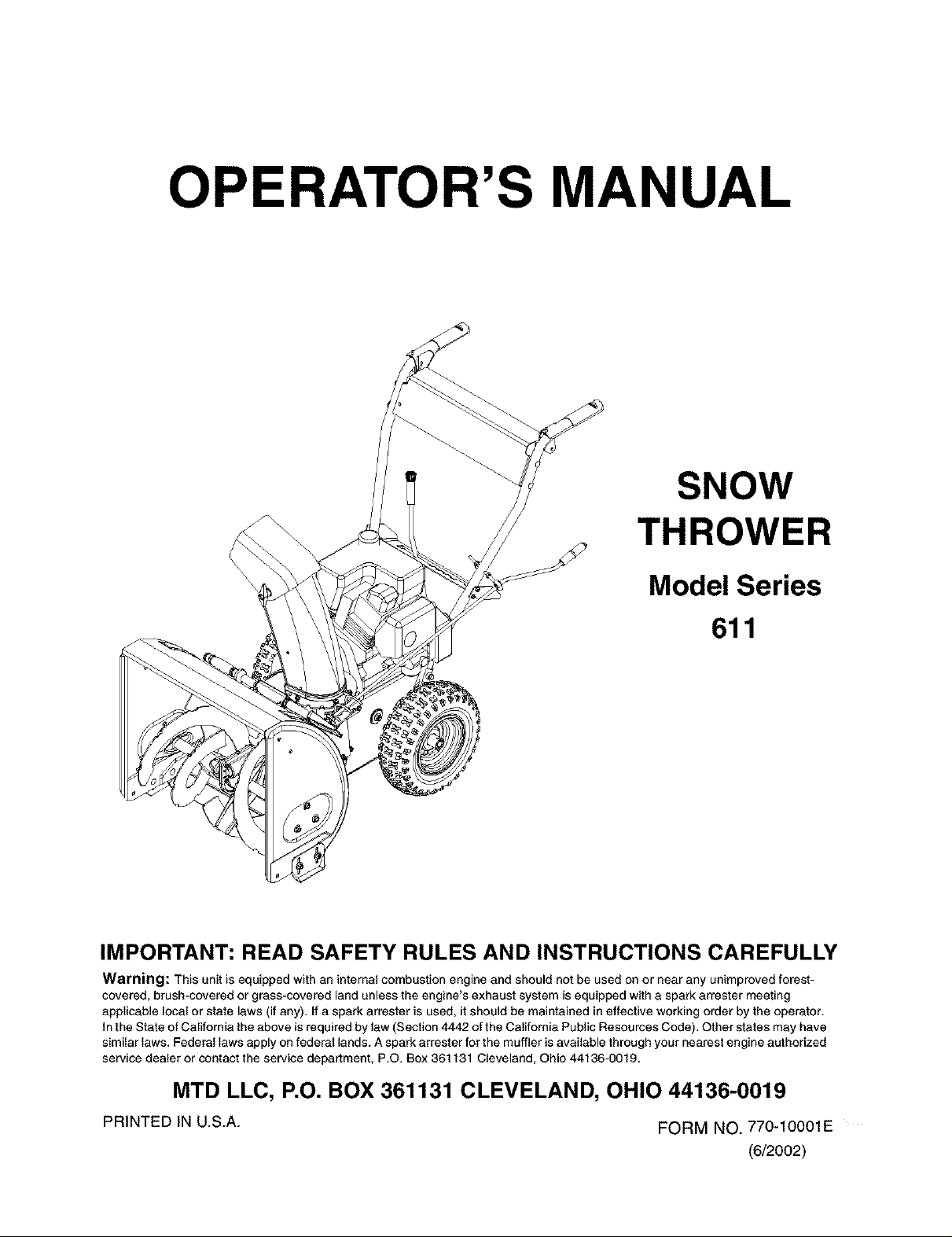
OPERATOR'S MANUAL
SNOW
THROWER
Model Series
611
IMPORTANT: READ SAFETY RULES AND INSTRUCTIONS CAREFULLY
Warning: This unit is equipped with an internal combustion engine and should not be used on ornear any unimproved forest-
covered, brush-covered or grass-covered land unless the engine's exhaust system is equipped with a spark arrester meeting
applicable local or state laws (if any). If a spark arrester is used, it should be maintained in effective working order by the operator.
In the State of California the above is required by law (Section 4442 of the California Public Resources Code). Other states may have
similar laws. Federal laws apply on federal lands. A spark arrester for the muffler is available through your nearest engine authorized
service dealer or contact the service department, P.O. Box 361131 Cleveland, Ohio 44136-0019.
MTD LLC, P.O. BOX 361131 CLEVELAND, OHIO 44136-0019
PRINTED IN U.S.A.
FORM NO. 770-10001E
(6/2002)
TABLEOFCONTENTS
Content Page
Important Safe Operation Practices ................................................................... 3
Hardware Pack .................................................................................................. 5
Assembling Your Snow Thrower ........................................................................ 6
Know Your Snow Thrower ................................................................................. 9
Operating Your Snow Thrower ........................................................................... 10
Making Adjustments .......................................................................................... 13
Maintaining Your Snow Thrower ........................................................................ 15
Service ............................................................................................................... 16
Troubleshooting ................................................................................................. 19
Parts List ............................................................................................................ 19
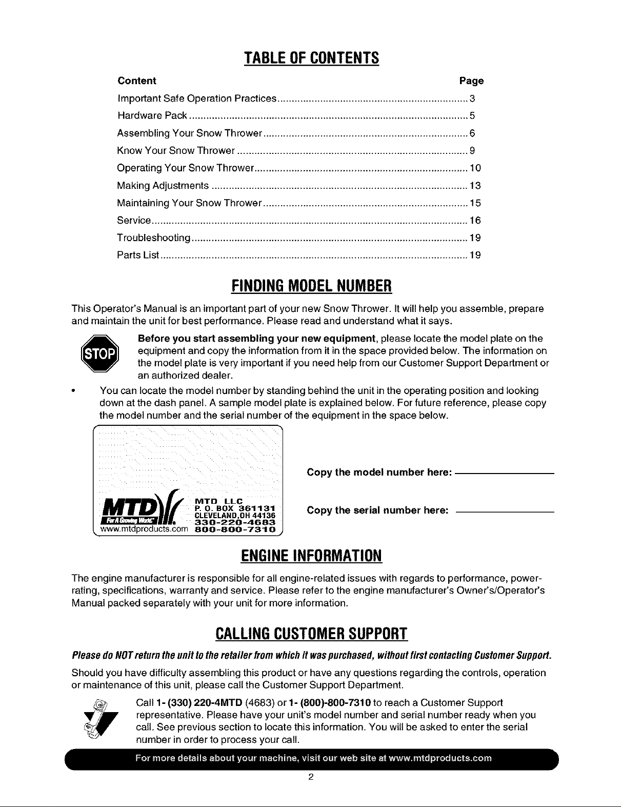
FINDINGMODELNUMBER
This Operator's Manual is an important part of your new Snow Thrower. It will help you assemble, prepare
and maintain the unit for best performance. Please read and understand what it says.
Before you start assembling your new equipment, please locate the model plate on the
equipment and copy the information from it in the space provided below. The information on
the model plate is very important if you need help from ourCustomer Support Department or
an authorized dealer.
You can locate the model number by standing behind the unit in the operating position and looking
down at the dash panel. A sample model plate is explained below. For future reference, please copy
the model number and the serial number of the equipment inthe space below.
Copy the model number here:
ii ii iiii
Copy the serial number here:
www.mtdproducts.com 800-800-7310
ENGINEINFORMATION
The engine manufacturer is responsible for all engine-related issues with regards to performance, power-
rating, specifications, warranty and service. Please refer to the engine manufacturer's Owner's/Operator's
Manual packed separately with your unit for more information.
CALLINGCUSTOMERSUPPORT
PleasedoNOTreturntheunitto theretailer fromwhichit waspurchased,withoutfirstcontactingCustomerSupport.
Should you have difficulty assembling this product or have any questions regarding the controls, operation
or maintenance of this unit, please call the Customer Support Department.
Call 1- (330) 220-4MTB (4683) or 1- (800)-800-7310 to reach a Customer Support
representative. Please have your unit's model number and serial number ready when you
call. See previous section to locate this information. You will be asked to enter the serial
number in order to process your call.
SECTION1: IMPORTANTSAFEOPERATIONPRACTICES
This symbol points out important safety instructions, which if not followed, could endanger the personal
safety and/or property of yourself and others. Read and follow all instructions in this manual before
attempting to operate this machine. Failure to comply with these instructions may result in personal
injury. When you see this symboliheed its warning.
WARNING: Engine Exhaust, some of its constituents, and certain vehicle components
contain or emit chemicals known to the State of California to cause cancer, birth defects or
other reproductive harm.
DANGER: This machine was built to be operated according to the rules for safe operation inthis
manual. As with any type of power equipment, carelessness or error on the part of the operator can
result in serious injury. This machine is capable of amputating hands and feet and throwing objects.
Failure to observe the following safety instructions could result in serious injury or death.
6.
TRAINING
1. Read, understand, and follow all instructions on the
machine and inthe manual(s) before attempting to
assemble and operate. Keep this manual in a safe place
for future and regular reference and for ordering
replacement parts.
2. Be familiar with all controls and their proper operation.
Know how to stop the machine and disengage them
quickly.
3. Never allow children under 14 years old to operate this
machine. Children 14 years old and over should read and
understand the operation instructions and safety rules in
this manual and should be trained and supervised by a
parent.
4. Never allow adults to operate this machine without
proper instruction.
5. Thrown objects can cause serious personal injury. Plan
your snow4hrowing pattern to avoid discharge of material
toward roads, bystanders and the like.
6. Keep bystanders, helpers, pets and children at least 75
feet from the machine while it is in operation. Stop
machine if anyone enters the area.
7. Exercise caution to avoid slipping or falling, especially
when operating in reverse.
PREPARATION
1. Thoroughly inspect the area where the equipment is to
be used. Remove all doormats, newspapers, sleds,
boards, wires and other foreign objects, which could be
tripped over or thrown by the augedimpeller.
2. Always wear safety glasses or eye shields during
operation and while performing an adjustment or repair to
protect your eyes. Thrown objects which ricochet can
cause serious injury to the eyes.
3. Do not operate without wearing adequate winter outer
garments. Do not wear jewelry, long scarves or other
loose clothing, which could become entangled in moving
parts. Wear footwear which will improve footing on
slippery surfaces.
4. Use a grounded three-wire extension cord and
receptacle for all units with electric start engines.
5. Adjust collector housing height to clear gravel or crushed
rock surfaces.
Disengage all clutch levers before starting the engine.
7.
Never attempt to make any adjustments while engine is
running, except where specifically recommended in the
operator's manual.
8.
Let engine and machine adjust to outdoor temperature
before starting to clear snow.
9.
To avoid personal injury or property damage use extreme
care in handling gasoline. Gasoline is extremely
flammable and the vapors are explosive. Serious
personal injury can occur when gasoline is spilled on
yourself or your clothes, which can ignite. Wash your skin
and change clothes immediately.
a. Use only an approved gasolinecontainer.
b. Extinguish all cigarettes, cigars, pipes and other
sources of ignition.
c. Never fuel machine indoors.
d. Never remove gas cap or add fuel while the
engine is hot or running.
e. Allow engine to cool at least two minutes before
refueling.
f. Never over fill fuel tank. Fill tank to nomore than
_/2inch below bottom of filler neck to provide space
for fuel expansion.
g. Replace gasoline capand tighten securely.
h. If gasoline is spilled, wipe it off the engine and
equipment. Move machine to another area. Wait 5
minutes before starting the engine.
i. Never store the machine or fuel container inside
where there is an open flame, spark or pilot light
(e.g. furnace, water heater, space heater, clothes
dryer etc.).
j. Allow machine to cool at least 5 minutes before
storing.
OPERATION
1. Do not put hands or feet near rotating parts, in the auger/
impeller housing or discharge chute. Contact with the
rotating parts can amputate hands and feet.
2. The auger/impeller clutch lever is a safety device. Never
bypass its operation. Doing so makes the machine
unsafe and may cause personal injury.
3. The clutch levers must operate easily in both directions
and automatically return to the disengaged position when
_leased.

4. Neveroperatewithamissingordamageddischarge
chute.Keepallsafetydevicesinplaceandworking.
5. Neverrunanengineindoorsorinapoorlyventilated
area.Engineexhaustcontainscarbonmonoxide,an
odorlessanddeadlygas.
6. Donotoperatemachinewhileundertheinfluenceof
alcoholordrugs.
7. Mufflerandenginebecomehotandcancauseaburn.Do
nottouch.
8. Exerciseextremecautionwhenoperatingonorcrossing
gravelsurfaces.Stayalertforhiddenhazardsortraffic.
9. Exercisecautionwhenchangingdirectionandwhile
operatingonslopes.
10.Planyoursnow-throwingpatterntoavoiddischarge
towardswindows,wails,carsetc.Thus,avoiding
possiblepropertydamageorpersonalinjurycausedbya
ricochet.
11.Neverdirectdischargeatchildren,bystandersandpets
orallowanyoneinfrontofthemachine.
12.Donotoverloadmachinecapacitybyattemptingtoclear
snowattoofastofarate.
13.Neveroperatethismachinewithoutgoodvisibilityor
light.Alwaysbesureofyourfootingandkeepafirmhold
onthehandles.Walk,neverrun.
14.Disengagepowertotheauger/impellerwhen
transportingornotinuse.
15.Neveroperatemachineathightransportspeedson
slipperysurfaces.Lookdownandbehindandusecare
wheninreverse.
16.Ifthemachineshouldstarttovibrateabnormally,stopthe
engine,disconnectthesparkplugwireandgroundit
againsttheengine.Inspectthoroughlyfordamage.
Repairanydamagebeforestartingandoperating.
17.Disengageallclutchleversandstopenginebeforeyou
leavetheoperatingposition(behindthehandles).Wait
untiltheauger/impellercomestoacompletestopbefore
uncloggingthedischargechute,makingany
adjustments,orinspections.
18.Neverputyourhandinthedischargeorcollector
openings.Alwaysusetheclean-outtoolprovidedto
unclogthedischargeopening.Donotunclogdischarge
chutewhileengineisrunning.Shutoffengineandremain
behindhandlesuntilallmovingpartshavestopped
beforeunclogging.
19.Useonlyattachmentsandaccessoriesapprovedbythe
manufacturer(e.g.wheelweights,tirechains,cabsetc.).
20.Ifsituationsoccurwhicharenotcoveredinthismanual,
usecareandgoodjudgment.Contactyourdealeror
telephone1-800-800-7310forassistanceandthename
ofyournearestservicingdealer.
MAINTENANCEANDSTORAGE
1. Never tamper with safety devices. Check their proper
operation regularly. Refer to the maintenance and
adjustment sections of this manual.
2. Before cleaning, repairing, or inspecting machine
disengage all clutch levers and stop engine. Wait until the
auger/impeller come to a complete stop. Disconnect the
spark plug wire and ground against the engine to prevent
unintended starting.
3. Check bolts and screws for proper tightness at frequent
intervals to keep the machine in safe working condition.
Also, visually inspect machine for any damage.
4. Do not change the engine governor setting or over-speed
the engine. The governor controls the maximum safe
operating speed of the engine.
5. Snow thrower shave plates and skid shoes are subject to
wear and damage. For your safety protection, frequently
check all components and replace with original
equipment manufacturer's (OEM) parts only. "Use of
parts which do not meet the original equipment
specifications may lead to improper performance and
compromise safety!"
6. Check dutch controls periodically to verify they engage
and disengage properly and adjust, ifnecessary. Refer to
the adjustment section in this operator's manual for
instructions.
7. Maintain or replace safety and instruction labels, as
necessary.
8. Observe proper disposal laws and regulations for gas,
oil, etc. to protect the environment.
9. Prior to storing, run machine a few minutes to clear snow
from machine and prevent freeze up of auger/impeller.
10. Never store the machine or fuel container inside where
there is an open flame, spark or pilot light such as a water
heater, furnace, clothes dryer etc.
11. Always refer to the operator's manual for proper
instructions on off-season storage.
power machine to persons who read,
WARNING: Restrict the use of this
understand and follow the warnings and
instructions in this manual and on the
machine.
5. READOPERATOR'SMANUAL.
C[.EAII-OUTTOOl.
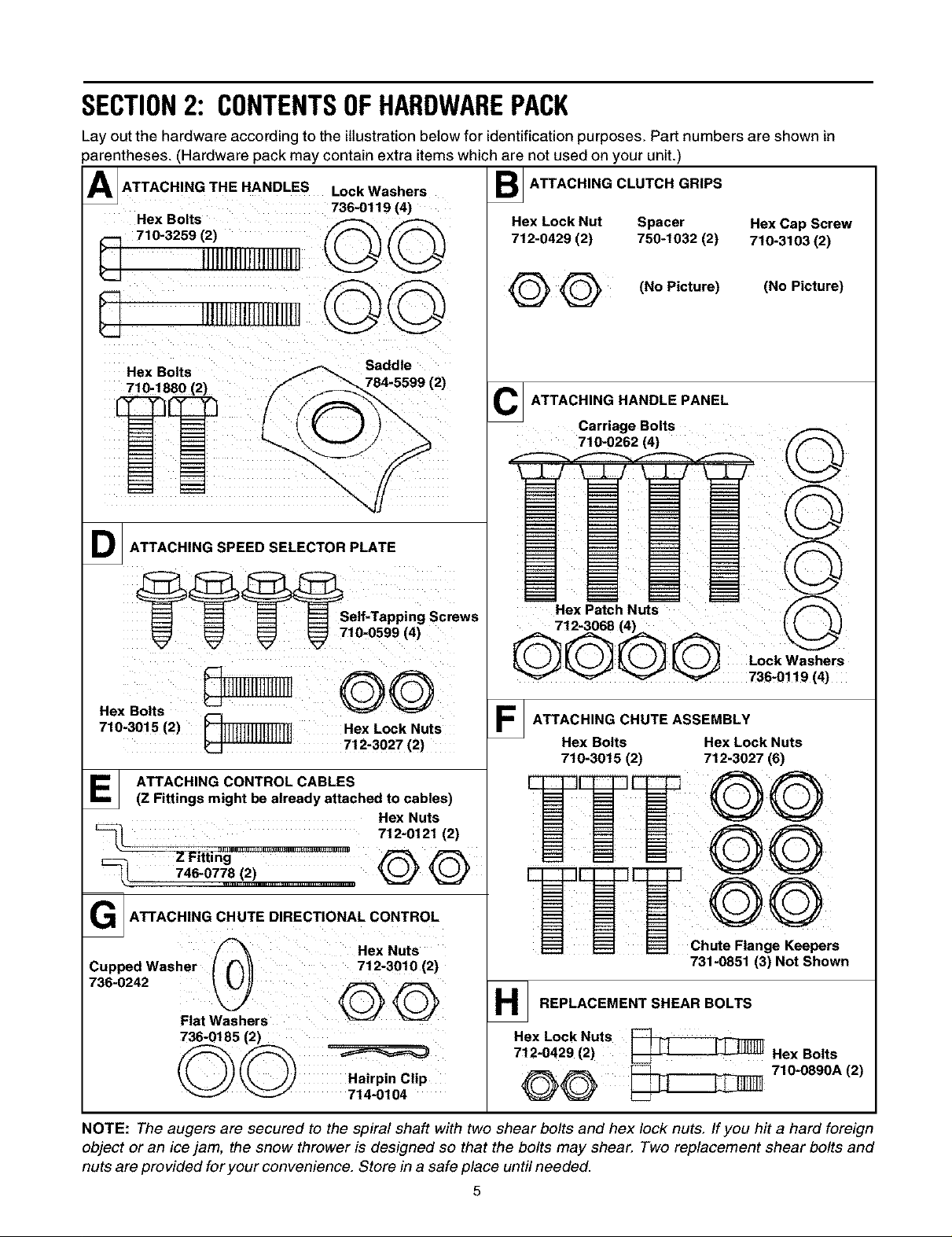
SECTION2: CONTENTSOFHARDWAREPACK
Lay out the hardware according to the illustration below for identification purposes. Part numbers are shown in
_arentheses. (Hardware pack may contain extra items which are not used on your unit.)
A_ ATTACHING THE HANDLES Lock Washers
736-0119 (4)
Hex Bolts _
ATTACHING CLUTCH GRIPS
Hex Lock Nut Spacer Hex Cap Screw
712-0429 (2) 750-1032 (2) 710-3103 (2)
8 '"'"''"""©@
Hex Bolts Saddle
7!0-!680 (2) 784.5599 (2)
D_ ATTACHING SPEED SELECTOR PLATE
Hex Bolts (--_
710.3015(2) _ Hex Lock Nuts
7!2,3027(2)
@@
C_ ATTACHING HANDLE PANEL
Carriage Bolts
710-0262 (4)
Hex Patch Nuts
712-3068 (4) i
____ Lock Washers
v _" v_ 736-0!!9 (4)
F_ ATTACHING CHUTE ASSEMBLY
Hex Bolts Hex Lock Nuts
710-3015 (2) 712-3027 (6)
(No Picture) (No Picture)
E_ ATTACHING CONTROL CABLES
(Z Fittings might be already attached to cables)
Hex Nuts
712-0121 (2)
746"0778..!2 _............................................. _
i ir-
G3 ATTAOH,NGCHUTED,REOTIONALCONTROL
Hex Nuts
Cupped Washer t ("_11 712-3010(2)
736-0242
REPLACEMENT SHEAR BOLTS
Chute Flange Keepers
731-0851 (3) Not Shown
Flatw ers
736-0185(2)
Hairpin Clip
_ 714-0104
NOTE: The augers are secured to the spiral shaft with two shear bolts and hex lock nuts. Ifyou hit a hard foreign
object or an icejam, the snow thrower is designed so that the bolts may shear. Two replacement shear bolts and
nuts are provided for your convenience. Store in a safe place until needed.
Hex Lock Nuts
712-0429 (2) _-_J__._H-J_
Hex Bolts
710-0890A (2)

SECTION3: ASSEMBLINGYOURSNOWTHROWER
NOTE: References to right or left side of the snow
thrower are determined from behind the unit in the
operating position. The "operator's position" is defined
as standing directly behind the snow thrower, facing the
handle panel
Unpacking
• Remove staples or break glue on top flaps of the
carton. Remove any loose parts included with unit
(i.e., operator's manual, etc.).
• Cut corners of the carton and lay ends down flat.
Remove packing material.
• Roll unit out of carton. Check carton thoroughly for
loose parts before discarding.
LoosePartsInCarton
Handl_ Panel ps
BeforeAssembly
WARNING: Disconnect the spark plug
wire and ground it against the engine to
prevent unintended starting.
AttachingHandles(HardwareGroupA)
• Place right handle in position against the snow
thrower so that the flat side of the handle is against
the frame. Align the bottom hole on the handle to
the corresponding hole on the snow thrower
housing.
• Insert hex bolt and lock washer through these holes
to secure the handle to the snow thrower housing.
Do not tighten at this time. See Figure 2.
Guide_
Hex Bolt & _
Clean-out \
jTool*
Figure 1
*This item is fastened with a cable tie to the rear of
the Auger Housing at the factory.
Lock Washer
Figure 2
Attach the left handle in the same manner and do
not tighten.
Place saddle washer over upper holes on handles
and secure to the frame with lock washers and hex
bolts. Do not tighten now. See Figure 2.
AttachingClutchGrips(HardwareGroupB)
• Slide spacer on each end of the clutch grip and
place the clutch grip in position on the each
respective handle. Clutch grips must sit on top of
the handles. See Figure 3.
_Hex Lock Nut
_ Hex Bolt
Spacer
Figure 3

• Secure each clutch grip with a hex bolt threaded
from the outside of each handle and tighten with
hex lock nut under handle panel. See Figure 3.
AttachingHandlePanel(HardwareGroupC)
• Position the handle panel between handles and
insert two carriage bolts on each side and secure
with lock washers and hex patch nuts.
See Figure 4.
Hex Cap Screw\
Carriage Hex Lock Nuts
Bolts
Self-Tappin_
Screws
Figure 4
ige
• Secure shift lever to the shift lever spring using two
hex bolts (G) and hex lock nuts (H). Tighten both
bolts finger tight. At this point the shift lever and
shift lever spring are not against each other. As you
tighten the bolts and nuts with two wrenches, these
will pull together.
• Tighten all hardware assembled to this point. Make
sure that clutch grips are moving freely.
AttachingControlCables(HardwareGroupE)
Z fittings with jam nuts might be already inserted in
each control lever (on the handle panel) at the factory.
To attach the cables to the Z fittings, proceed as
follows:
NOTE: Two extra jam nuts are included in the hardware
pack in the event either are lost during shipping.
• If Z fittings are not already attached, thread hex
nuts onto the "Z" fittings and insert "Z" fitting into
hole in clutch grips. See Figure 6.
• Route the left cable between engine and speed
selector plate and then between handle panel and
clutch lever pivot rod before threading onto the left
"Z" fitting.
• Assemble the right cable inthe same manner.
• Both cables should have minimal slack, but not
tight.
AttachingSpeed Selector Plate
(HardwareGroupD)
Assemble the speed selector plate to the outside
of the handles. Secure using two self-tapping
screws on each side. See Figure 5.
Shift Lever
Figure 5
AttachingShiftLever
• Insert the shift lever through slot in the speed
selector plate. See Figure 5.
NOTE: The bend in the lever should be towards the
operator.
Jam Nut
Figure 6
• If Z fittings are already attached, thread the jam
nuts all the way up each of the Z fittings, toward the
handle panel.
• Make certain all cables are inthe grooves of the
cable roller guides in the lower rear of the unit, one
on each side. Refer to Figure 2.
• Thread the coupling end of the cable onto the
threaded portion of the Z fitting until the rubber
bumper (located on the underside of the clutch
lever) only lightly contacts the upper handle.
IMPORTAWr: The cable should have very little slack, but
should NOT be tight. An overtightened cable may
prohibit the auger and drive from disengaging.
• Once properly adjusted, tighten the jam nut against
the coupling end of the cable to lock it in position.
WARNING: Over-tightening the cable
may prohibit the auger and drive from
disengaging and compromise the safety
of the snow thrower. Do NOT overtighten
the cable.
Hex Bolts &
Hex Lock Nuts
NOTE:
Refer to AugerControlTest in the Operation
Section prior to operating your snow thrower. Read and
follow all instructions carefully and perform all
adjustments to verify your snow thrower is operating
safely and properly.
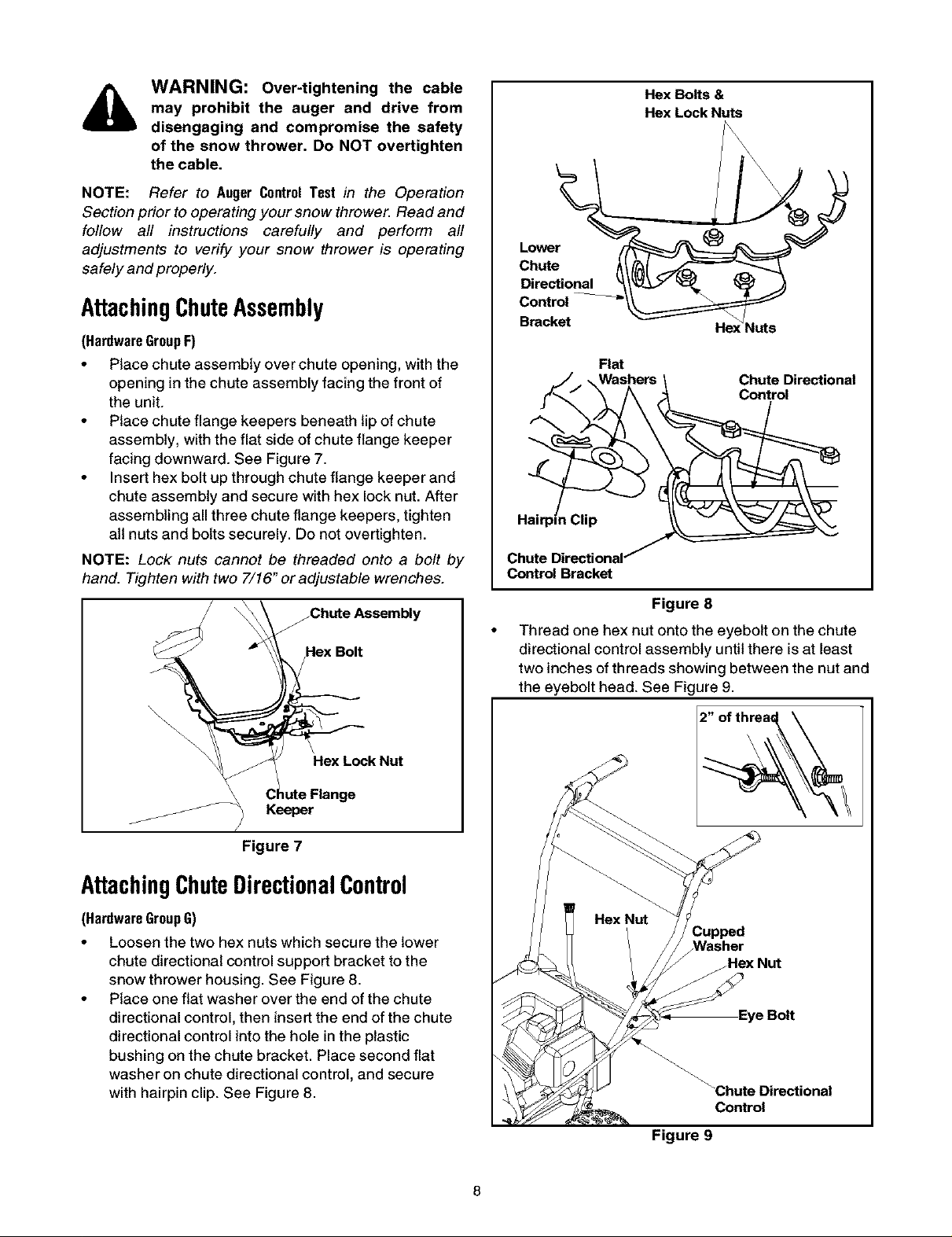
AttachingChuteAssembly
(HardwareGroupF)
• Place chute assembly over chute opening, with the
opening in the chute assembly facing the front of
the unit.
• Place chute flange keepers beneath lip of chute
assembly, with the flat side of chute flange keeper
facing downward. See Figure 7.
• Insert hex bolt up through chute flange keeper and
chute assembly and secure with hex lock nut. After
assembling all three chute flange keepers, tighten
all nuts and bolts securely. Do not overtighten.
NOTE: Lock nuts cannot be threaded onto a bolt by
hand. Tighten with two 7/16" or adjustable wrenches.
Lower
Chute
Directional
Control \
Bracket He:
Flat
Washers
Control Bracket
_luts
Chute Directional
Control
Figure 8
Thread one hex nut onto the eyebolt on the chute
directional control assembly until there is at least
two inches of threads showing between the nut and
the eyebolt head. See Figure 9.
Figure 7
AttachingChuteDirectionalControl
(HardwareGroupG)
• Loosen the two hex nuts which secure the lower
chute directional control support bracket to the
snow thrower housing. See Figure 8.
• Place one flat washer over the end of the chute
directional control, then insert the end of the chute
directional control into the hole in the plastic
bushing on the chute bracket. Place second flat
washer on chute directional control, and secure
with hairpin clip. See Figure 8.
2" of threal;_
Control
Figure 9
• Place the eyebott into the hole located half way up
the left handle and secure with cupped washer and
hex nut making sure that the cupped side of the
washer is against the handle.
• Adjust the chute directional control bracket so that
the spiral on the chute directional control fully
engages the teeth on the chute assembly. Tighten
all hardware. See Figure 10.
• Check to make sure all nuts and bolts on the control
panel and all four bolts which secure the handles to
the frame are tight.
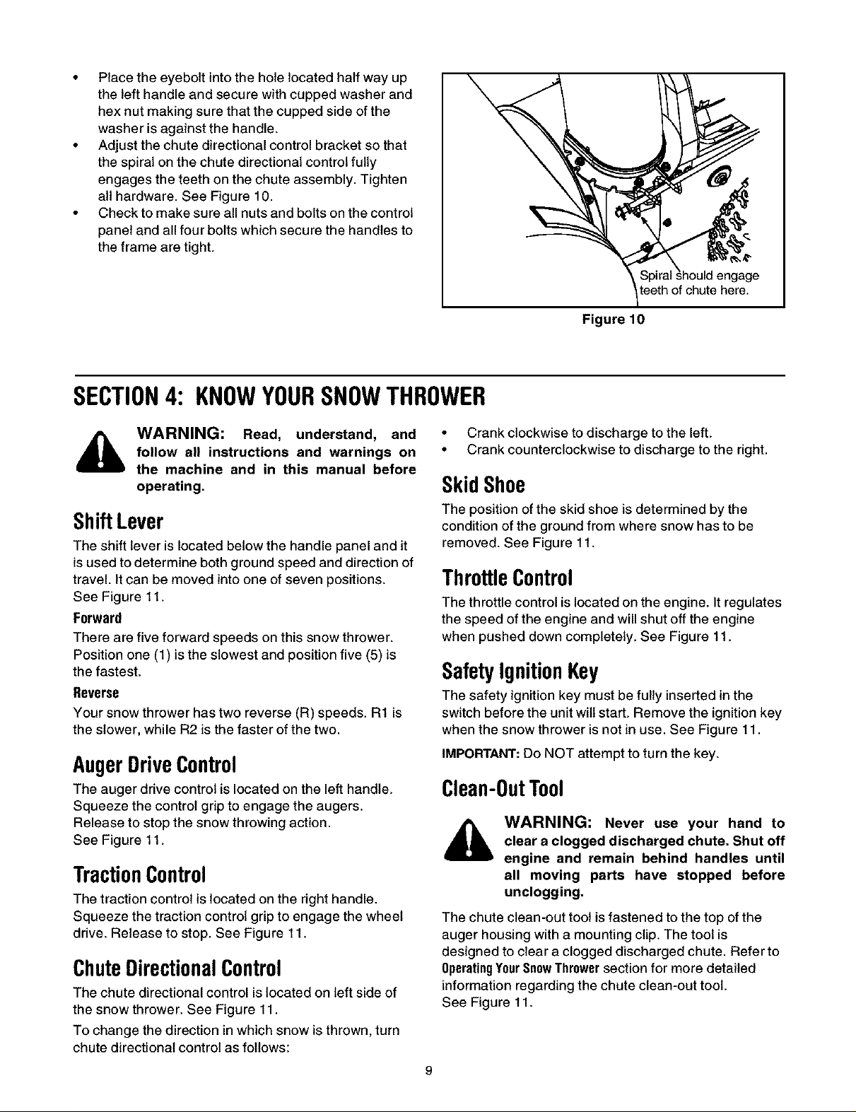
SECTION4: KNOWYOURSNOWTHROWER
teeth of chute here.
Figure lg
WARNING: Read, understand, and
follow all instructions and warnings on
the machine and in this manual before
operating.
ShiftLever
The shift lever is located below the handle panel and it
is used to determine both ground speed and direction of
travel. Itcan be moved into one of seven positions.
See Figure 11.
Forward
There are five forward speeds on this snow thrower.
Position one (1) is the slowest and position five (5) is
the fastest.
Reverse
Your snow thrower has two reverse (R) speeds. R1 is
the slower, while R2 is the faster of the two.
AugerDriveControl
The auger drive control is located on the left handle.
Squeeze the control grip to engage the augers.
Release to stop the snow throwing action.
See Figure 11.
TractionControl
The traction control is located on the right handle.
Squeeze the traction control grip to engage the wheel
drive. Release to stop. See Figure 11.
ChuteDirectionalControl
The chute directional control is located on left side of
the snow thrower. See Figure 11.
To change the direction in which snow is thrown, turn
chute directional control as follows:
• Crank clockwise to discharge to the left.
• Crank counterclockwise to discharge to the right.
SkidShoe
The position of the skid shoe is determined by the
condition of the ground from where snow has to be
removed. See Figure 11.
ThrottleControl
The throttle control is located on the engine. It regulates
the speed of the engine and will shut off the engine
when pushed down completely. See Figure 11.
SafetyIgnitionKey
The safety ignition key must be fully inserted in the
switch before the unit wilt start. Remove the ignition key
when the snow thrower is not in use. See Figure 11.
IMPORTANT: Do NOT attempt to turn the key.
Clean-OutTool
WARNING: Never use your hand to
clear a clogged discharged chute. Shut off
engine and remain behind handles until
all moving parts have stopped before
unclogging.
The chute clean-out toot is fastened to the top of the
auger housing with a mounting clip. The tool is
designed to clear a clogged discharged chute. Refer to
OperatingYourSnowThrowersection for more detailed
information regarding the chute clean-out tool.
See Figure 11.
 Loading...