

MTD 31AS6BN2711 Service Manual
Service Manual
NOTE: These materials are for use by trained technicians who are experienced in the service and repair of outdoor power
equipment of the kind described in this publication, and are not intended for use by untrained or inexperienced individuals. These
materials are intended to provide supplemental information to assist the trained technician. Untrained or inexperienced individuals
should seek the assistance of an experienced and trained professional. Read, understand, and follow all instructions and common
sense when working on power equipment. This includes the contents of the product’s Operators Manual, supplied with the
equipment. No liability can be accepted for any inaccuracies or omission in this publication, although care has been taken to make
it as complete and accurate as possible at the time of publication. However, due to the variety of outdoor power equipment and
continuing product changes that occur over time, updates will be made to these instructions from time to time. Therefore, it may
be necessary to obtain the latest materials before servicing or repairing a product. The company reserves the right to make
changes at any time to this publication without prior notice and without incurring an obligation to make such changes to previously
published versions. Instructions, photographs and illustrations used in this publication are for reference use only and may not
depict actual model and component parts. © Copyright 2005 MTD Products Inc. All Rights Reserved
Model 31AS6BN2711 Two-Stage Snow Thrower
MTD Products LLC - Product Training and Education Department
FORM NUMBER 769-01420
9/2004


SERVICE MANUAL
31AS6BN-711 Snow Thrower
Tire Pressure ..............................................................................................................................1
Chute Installation .........................................................................................................................2
Discharge Chute Removal ...........................................................................................................2
Directional Control Assembly .......................................................................................................2
Chute Bracket Adjustment ...........................................................................................................2
Skid Shoe and Shave Plate Adjustment .....................................................................................2
The Shave Plate Adjustment........................................................................................................3
Drive Control Cable Adjustment ..................................................................................................3
Auger Control Testing and Adjustment .......................................................................................4
Shift Rod Adjustment .................................................................................................................5
Auger Belt Replacement .............................................................................................................5
Drive Belt Replacement .............................................................................................................7
Friction Wheel Removal........... ...................................................................................................7
Axle Shaft RemovalL ...................................................................................................................9
Splitting the Unit ........................................................................................................................10
Friction Wheel Disc Disassembly ..............................................................................................11
Auger Pulley Removal ...............................................................................................................11
Auger and Impeller Removal .....................................................................................................12
Reducer Transmission................................................................................................................13
Reduction Transmission Disassembly .......................................................................................14
Auger Idler Arm ..........................................................................................................................14
Chute Disassembly ....................................................................................................................15
1

SERVICE MANUAL
31AS6BN2-711 Snow Thrower
31AS6BN2711 (TROY-BILT AS SPECIFIED FOR
LOWE’S
SNOW THROWER MODEL NUMBER 31AS6BN2711
SERIAL # 1G144B40028
• Two Stage 5.5 HP Electric Start
• 24” Clearing Width
• 6 Forward Speeds and 2 Reverse Speeds
• X – Track Tires
GENERAL INFORMATION
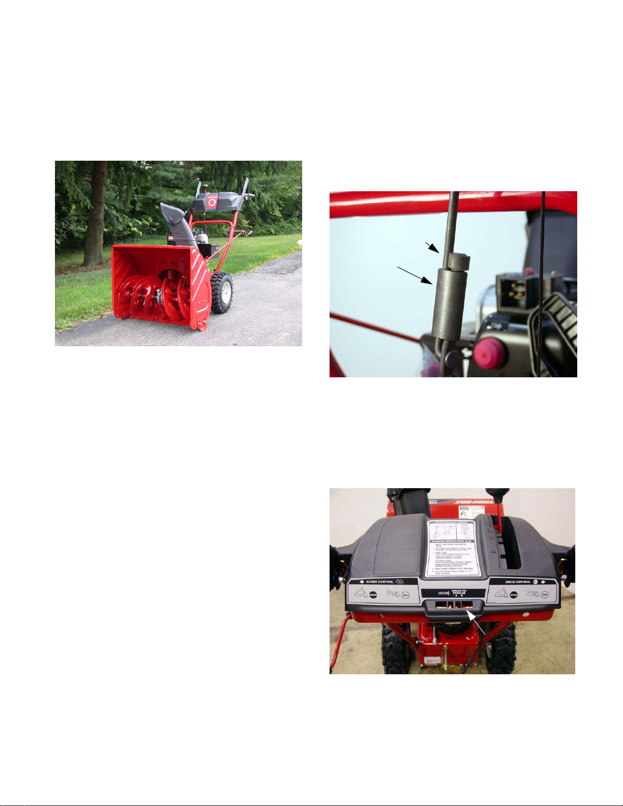
Secure it in place by placing a rubber bushing over the
top of the lower shift rod OR the upper shift rod. (A
small piece of gas line can be used as a bushing.) This
will prevent the sleeve from sliding up the shaft. See
Figure 1.
Rubber Bushing
Connecter Sleeve
Figure 1
Rubber bands hold the Auger and Drive control cables
in their respective nylon pulleys during shipping and
generally break during assembly of the handle.
Remove any pieces of rubber band after assembly.
There is a storage area in the handle panel used for
holding the spare auger shear pins. See Figure 2.
The Owner’s Manual packet includes and engine manual, extra shear pins and cotter pins as well as a packet
containing a sample of Sta-Bill fuel stabilizer that will
treat up to 2 ½ gallons of regular gas.
CAUTION: When assembling the handle for the
first time, use caution when lifting the handle.
The shift lever rod can get caught on the lower
handle cross member and if forced into position
can bend the spring shift lever. If necessary,
move the shift rod in front of the cross member
as you raise the handle into position.
There are two Supplement Sheet dated July 19, 2004,
and July 20, 2004 – Subject: Connector Sleeve on Two
Stage Snow Thrower shift rod. (Styles: E, F, H, K, L, N,
O, P and Q.)
Vibration may cause the rod connector sleeve to slide
up out of position. The remedy is to slide the connecter
sleeve fully down.
Shear Pin Storage
Figure 2
1. TIRE PRESSURE
Before operating, check tire pressure. Both tires should
be between 15 psi and 20 psi.
1
NOTE: If the tire pressure is not equal in both tires, the
unit may pull to one side or the other during operation.
2. CHUTE INSTALLATION
4.2. Insert the end of the chute directional control into
the lower bracket and secure with the flat
washer and hairpin clip. See Figure 4.
2.1. Apply a light lubricant to the rim/lip of the chute
base (and the underside of the chute assembly)
and position the chute over the base.
2.2. Close the flange keepers to secure the chute to
the base. See Figure 3.
Third flange keeper is at front of chute
Open flange keeper
Closed flange keeper
Figure 3
NOTE: If the flange keepers will not easily click
into place, use the palm of your hand to apply
swift, firm pressure to the back of each.
Directional Control Lever
Hairpin Clip Washer
Figure 4
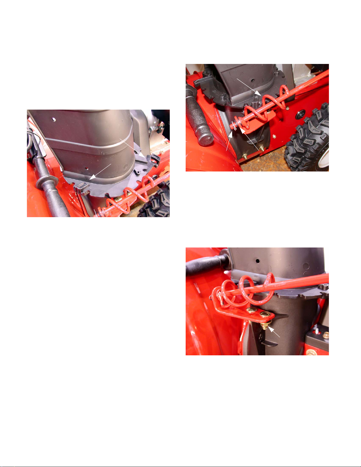
5. CHUTE BRACKET ADJUSTMENT
If necessary the Chute Bracket can be adjusted if the
spiral at the bottom of the directional control is not fully
engaging the chute assembly.
5.1. Loosen the two nuts, which secure the chute
bracket and reposition it slightly before retightening the nuts. See Figure 5.
3. DISCHARGE CHUTE REMOVAL
3.1. To remove the discharge chute, use the bladeside of a screwdriver by wedging between the
housing and the flange keepers and with a lifting
and prying motion lift the locking flange out of
the locked position and pivot the flange keepers
outwards.
3.2. Lift the chute assembly off the mounting base of
the main housing.
4. DIRECTIONAL CONTROL ASSEMBLY
4.1. Remove the flat washer and hairpin clip from the
end of the chute directional control.
Adjustment Nuts
Figure 5
6. SKID SHOE AND SHAVE PLATE ADJUSTMENT
The space between the shave plate and the ground
can be adjusted.
For close snow removal on a smooth surface, raise
skid shoes higher on the auger housing to lower the
shave plate.
2
 Loading...