

MTD 31AS62EE799 Owner’s Manual
Operator's Manual
CRRFTSMRN
24" SNOW THROWER
Model No. 247.889571
o SAFETY
ASSEMBLY
OPERATION
MAINTENANCE
CAUTION: Before using
this product, read this
PARTS LIST
o ESPANOL
manual and follow all
safety rules and operating
instructions.
Sears Brands Management Corporation, Hoffman Estates, IL 60179, U.S.A.
Visit our website: www.craftsman.com FORM1/0.769-05095D
7/26/2011

WarrantyStatement.................... Page2
SafeOperationPractices.............. Pages3-6
Assembly......................... Pages8-11
Operation........................ Pages12-15
Service&Maintenance.............. Pages16-23
Off-SeasonStorage................... Page24
Troubleshooting...................... Page25
PartsList......................... Pages26-42
RepairProtectionAgreement............ Page47
Espa_ol............................. Page48
CRAFTSMANTWOYEARFULLWARRANTY
FORTWOYEARSfromthedateofpurchase,thisproductiswarrantedagainstanydefectsinmaterialorworkmanship.Defectiveproductwill
receivefreerepairorfreereplacementifrepairisunavailable.
Thiswarrantyisvoidifthisproductiseverusedwhileprovidingcommercialservicesorifrentedtoanotherperson.
Forwarrantycoveragedetails to obtain repairor replacement,visit the website: www.craftsman.com
This warranty covers ONLYdefects in material andworkmanship. Warrantycoveragedoes NOTinclude:
• Expendableitemsthatcanwearoutfromnormalusewithinthewarrantyperiod,includingbutnot limitedto augers,augerpaddles,drift
cutters,skidshoes,shaveplate,shearpins,sparkplug,aircleaner,belts,andoil filter.
• Standardmaintenanceservicing,oilchanges,ortune-ups.
• Tirereplacementor repaircausedbypuncturesfromoutsideobjects,suchasnails,thorns,stumps,orglass.
Tireor wheelreplacementor repairresultingfromnormalwear,accident,orimproperoperationor maintenance.
• Repairsnecessarybecauseof operatorabuse,includingbutnot limitedto damagecausedbyover-speedingthe engine,or fromimpacting
objectsthatbendtheframe,augershaft,etc.
• Repairsnecessarybecauseof operatornegligence,includingbutnotlimitedto,electricalandmechanicaldamagecausedbyimproper
storage,failureto usethepropergradeandamountofengineoil,or failureto maintaintheequipmentaccordingtotheinstructionscontained
intheoperator'smanual.
• Engine(fuelsystem)cleaningorrepairscausedbyfueldeterminedto becontaminatedoroxidized(stale).In general,fuelshouldbeused
within30 daysof itspurchasedate.
Normaldeteriorationandwearofthe exteriorfinishes,orproductlabelreplacement.
Thiswarrantygivesyouspecificlegalrights,andyoumayalsohaveotherrightswhichvaryfromstatetostate.
Sears Brands Management Corporation, Hoffman Estates, IL 60179
EngineOilType: 5W-30
EngineOilCapacity: 20ounces
FuelCapacity: 2.3Quarts
SparkPlug: F6RTC(951-10292)
SparkPlugGap: .020"to.030"
©KCDIR LLC
Model Number.................................................................
Serial Number .................................................................
Dateof Purchase.............................................................
Recordthemodelnumber,serialnumber
anddateof purchaseabove
2

Thissymbolpointsoutimportantsafetyinstructionswhich,if not
followed,couldendangerthepersonalsafetyand/orpropertyof
yourselfandothers. Readandfollowall instructionsin thismanual
beforeattemptingto operatethismachine.Failureto complywith
theseinstructionsmayresultin personalinjury.Whenyouseethis
symbol,HEEDITSWARNING!
Thismachinewasbuilttobeoperatedaccordingtothe safeopera-
tionpracticesinthis manual.Aswithanytypeof powerequipment,
carelessnessorerroron thepartoftheoperatorcanresultin serious
injury.Thismachineiscapableofamputatingfingers,hands,toes
andfeetandthrowingdebris.Failuretoobservethefollowingsafety
instructionscouldresultin seriousinjuryor death.
CALIFORNIA PROPOSITION 65
EngineExhaust,someof itsconstituents,andcertainvehicle
componentscontainoremitchemicalsknowntoStateofCalifornia
tocausecancerandbirthdefectsorotherreproductiveharm,
TRAiNiNG
• Read,understand,andfollowall instructionsonthemachineand
in themanual(s)beforeattemptingtoassembleandoperate.
Failuretodo socan resultinseriousinjurytothe operatorand/
orbystanders.Keepthismanualina safeplaceforfutureand
regularreferenceandfor orderingreplacementparts.
• Befamiliarwithall controlsandtheir properoperation.Knowhow
tostopthemachineanddisengagethemquickly.
• Neverallowchildrenunder14yearsofageto operatethis
machine.Children14andover shouldreadandunderstandthe
instructionsandsafeoperationpracticesin thismanualandon
themachineandbe trainedandsupervisedbyanadult.
Neverallowadultsto operatethis machinewithoutproper
instruction.
• Thrownobjectscancauseseriouspersonalinjury.Planyour
snow-throwingpatterntoavoiddischargeof materialtoward
roads,bystandersandthe like.
Keepbystanders,petsandchildrenat least75feetfromthe
machinewhileitisin operation.Stopmachineifanyoneenters
thearea.
• Exercisecautiontoavoidslippingorfalling,especiallywhen
operatinginreverse.
Your Responsibility--Restrict theuseofthispowermachineto
personswhoread,understandandfollowthewarningsand instruc-
tionsin thismanualandon themachine,
SAVE THESE INSTRUCTIONS!
PREPARATION
Thoroughlyinspecttheareawheretheequipmentistobeused.
Removeall doormats,newspapers,sleds,boards,wiresandother
foreignobjects,whichcouldbe trippedoverorthrownbytheauger/
impeller.
• Alwayswearsafetyglassesoreyeshieldsduringoperationand
whileperformingan adjustmentor repairto protectyoureyes.
Thrownobjectswhichricochetcancauseseriousinjurytothe
eyes.
Donot operatewithoutwearingadequatewinteroutergarments.
Donot wearjewelry,longscarvesorotherlooseclothing,which
couldbecomeentangledinmovingparts.Wearfootwearwhich
willimprovefootingonslipperysurfaces.
Usea groundedthree-wireextensioncordand receptaclefor all
machineswithelectricstartengines.
Disengageall controlleversbeforestartingtheengine.
Adjustcollectorhousingheighttocleargravelorcrushedrock
surfaces.
• Neverattemptto makeanyadjustmentswhileengineis running,
exceptwherespecificallyrecommendedintheoperator'smanual.
Letengineandmachineadjusttooutdoortemperaturebefore
startingtoclearsnow.
3
SafeHandlingof Gasoline
Toavoidpersonalinjuryor propertydamageuseextremecarein
handlinggasoline.Gasolineisextremelyflammableandthevaporsare
explosive.Seriouspersonalinjurycanoccurwhengasolineis spilled
onyourselforyourclotheswhichcan ignite.Washyourskinand
changeclothesimmediately.
• Useonlyanapprovedgasolinecontainer.
• Extinguishall cigarettes,cigars,pipesandothersources
ofignition.
• Neverfuelmachineindoors.
• Neverremovegas capor addfuelwhilethe engineis hot
or running.
• Allowenginetocoolat leasttwo minutesbeforerefueling.
• Neveroverfillfueltank.Filltanktono morethan1/2inch
belowbottomoffillerneckto providespaceforfuel
expansion.
• Replacegasolinecapandtightensecurely.
• Ifgasolineisspilled,wipeit offtheengineandequipment.
Movemachinetoanotherarea.Wait5 minutesbefore
startingtheengine.
• Neverstorethemachineor fuelcontainerinsidewhere
thereis anopenflame,sparkor pilotlight(e.g.furnace,
waterheater,spaceheater,clothesdryeretc.).
• Allowmachinetocoolatleast5 minutesbeforestoring.
• Neverfillcontainersinsidea vehicleor ona truckor trailer
bedwitha plasticliner.Alwaysplacecontainersonthe
groundawayfromyourvehiclebeforefilling.
• If possible,removegas-poweredequipmentfromthetruck
ortrailerand refueliton theground.Ifthisis not possible,
thenrefuelsuchequipmentona trailerwitha portable
container,ratherthanfromagasolinedispensernozzle.
• Keepthenozzleincontactwiththe rimofthefueltankor
containeropeningatalltimesuntilfuelingiscomplete.Do
notuse a nozzlelock-opendevice.
OPERATION
• Donotputhandsorfeetnear rotatingparts,in theauger/impeller
housingorchuteassembly.Contactwiththerotatingpartscan
amputatehandsandfeet.
• Theauger/impellercontrolleveris a safetydevice.Neverbypass
itsoperation.Doingsomakesthemachineunsafeandmaycause
personalinjury.
• Thecontrolleversmustoperateeasilyin bothdirectionsand
automaticallyreturntothedisengagedpositionwhenreleased.
• Neveroperatewitha missingordamagedchuteassembly.Keep
all safetydevicesin placeandworking.
• Neverrunanengineindoorsor ina poorlyventilatedarea.Engine
exhaustcontainscarbonmonoxide,anodorlessanddeadlygas.
• Donotoperatemachinewhileunderthe influenceofalcoholor
drugs.
• Mufflerandenginebecomehotandcan causea burn.Donot
touch.Keepchildrenaway.
• Exerciseextremecautionwhenoperatingonorcrossinggravel
surfaces.Stayalertforhiddenhazardsortraffic.
• Exercisecautionwhenchangingdirectionandwhileoperatingon
slopes.Do notoperateonsteepslopes.
• Planyoursnow-throwingpatternto avoiddischargetowards
windows,walls,carsetc.Thus,avoidingpossibleproperty
damageorpersonalinjurycausedbya ricochet.
• Neverdirectdischargeatchildren,bystandersand petsor allow
anyoneinfrontofthemachine.
• Donotoverloadmachinecapacitybyattemptingtoclearsnowat
toofastof arate.
• Neveroperatethis machinewithoutgoodvisibilityorlight.Always
be sureofyourfootingand keepafirmholdon the handles.Walk,
neverrun.
• Disengagepowertotheauger/impellerwhentransportingor not
in use.
• Neveroperatemachineat hightransportspeedsonslippery
surfaces.Lookdownand behindand usecare whenbackingup.
• Ifthemachineshouldstartto vibrateabnormally,stoptheengine,
disconnectthesparkplugwire andgrounditagainsttheengine.
Inspectthoroughlyfor damage.Repairanydamagebefore
startingandoperating.
• Disengageall controlleversandstopenginebeforeyouleave
theoperatingposition(behindthehandles).Waituntilthe auger/
impellercomestoa completestopbeforeuncloggingthechute
assembly,makingany adjustments,or inspections.
• Neverput yourhandinthe dischargeorcollectoropenings.Do
notunclogchuteassemblywhileengineisrunning.Shutoff
engineand remainbehindhandlesuntilall movingpartshave
stoppedbeforeunclogging.
• Useonlyattachmentsandaccessoriesapprovedbythemanufac-
turer(e.g.wheelweights,tirechains,cabsetc.).
• Whenstartingengine,pullcordslowlyuntilresistanceisfelt,then
pull rapidly.Rapidretractionofstartercord(kickback)willpull
handandarmtowardenginefasterthan youcanletgo.Broken
bones,fractures,bruisesorsprainscouldresult.
• Ifsituationsoccurwhichare notcoveredinthis manual,usecare
andgoodjudgment.
• Forin-warrantysafety,operationormaintenancequestions,or to
orderpartsandscheduleservice,call 1-800-4-MY-HOME.
CLEARING A CLOGGED DISCHARGE CHUTE
Handcontactwiththe rotatingimpellerinsidethedischargechute
is themostcommoncauseofinjuryassociatedwithsnowthrowers.
Neveruseyourhandtocleanoutthedischargechute.
Toclear thechute:
1. SHUTTHEENGINEOFF!
2. Wait 10secondstobe suretheimpellerbladeshavestopped
rotating.
3. Alwaysusea clean-outtool,not yourhands.
4
MAINTENANCE & STORAGE
• Nevertamperwithsafetydevices.Checktheirproperoperation
regularly.Refertothemaintenanceandadjustmentsectionsof
thismanual.
• Beforecleaning,repairing,or inspectingmachinedisengageall
controlleversandstopthe engine.Waituntilthe auger/impeller
cometoa completestop.Disconnectthe sparkplugwireand
groundagainsttheengineto preventunintendedstarting.
Checkboltsand screwsfor propertightnessat frequentintervals
tokeepthe machineinsafeworkingcondition.Also,visually
inspectmachineforanydamage.
Donotchangetheenginegovernorsettingor over-speedthe
engine.Thegovernorcontrolsthe maximumsafeoperatingspeed
oftheengine.
Snowthrowershaveplatesandskidshoesaresubjecttowear
anddamage.Foryoursafetyprotection,frequentlycheckall
componentsand replacewithoriginalequipmentmanufacturer's
(OEM)partsonlyas listedinthe Partspagesof thisoperator's
manual.Useofpartswhichdonot meetthe originalequipment
specificationsmayleadto improperperformanceandcompro-
misesafety!
Checkcontrolleversperiodicallytoverifytheyengageanddisen-
gageproperlyandadjust,ifnecessary.Refertotheadjustment
sectioninthisoperator'smanualforinstructions.
Maintainor replacesafetyandinstructionlabels,asnecessary.
Observeproperdisposallawsand regulationsfor gas,oil,etc. to
protecttheenvironment.
Priorto storing,runmachinea fewminutestoclearsnowfrom
machineand preventfreezeupof auger/impeller.
Neverstorethemachineorfuelcontainerinsidewherethereisan
openflame,sparkorpilotlightsuchasa waterheater,furnace,
clothesdryeretc.
Alwaysrefertotheoperator'smanualforproperinstructionson
off-seasonstorage.
Checkfuelline,tank,cap,andfittingsfrequentlyforcracksor
leaks.Replaceif necessary.
Donotcrankenginewithsparkplugremoved.
AccordingtotheConsumerProductsSafetyCommission(CPSC)
andtheU.S.EnvironmentalProtectionAgency(EPA),thisproduct
hasan AverageUsefulLifeof seven(7)years,or 60 hoursof
operation.Attheendof theAverageUsefulLifehavethemachine
inspectedannuallybyan authorizedservicedealerto ensurethat
allmechanicalandsafetysystemsareworkingproperlyand not
wornexcessively.Failuretodo so can resultinaccidents,injuries
ordeath.
DO NOT MODIFY ENGINE
Toavoidseriousinjuryor death,do notmodifyengineinanyway.
Tamperingwiththegovernorsettingcanleadtoa runawayengineand
causeittooperateat unsafespeeds.Nevertamperwithfactorysetting
ofenginegovernor.
NOTICE REGARDING EMiSSiONS
EngineswhicharecertifiedtocomplywithCaliforniaandfederal
EPAemissionregulationsforSORE(SmallOff RoadEquipment)are
certifiedto operateon regularunleadedgasoline,and mayinclude
thefollowingemissioncontrolsystems:EngineModification(EM),
OxidizingCatalyst(OC),SecondaryAirInjection(SAI)and ThreeWay
Catalyst(TWO)if soequipped.
SPARK ARRESTOR
Thismachineisequippedwithaninternalcombustionengineand
shouldnotbe usedonor nearanyunimprovedforest-covered,
brush-coveredorgrass-coveredlandunlesstheengine'sexhaust
systemisequippedwitha sparkarrestormeetingapplicablelocalor
statelaws(ifany)
Ifa sparkarrestorisused,itshouldbe maintainedin effectiveworking
orderbytheoperator.IntheStateof Californiatheaboveis required
bylaw (Section4442oftheCaliforniaPublicResourcesCode).Other
statesmayhavesimilarlaws. Federallawsapplyonfederallands.
A sparkarrestorforthemufflerisavailablethroughyournearestSears
PartsandRepairServiceCenter.
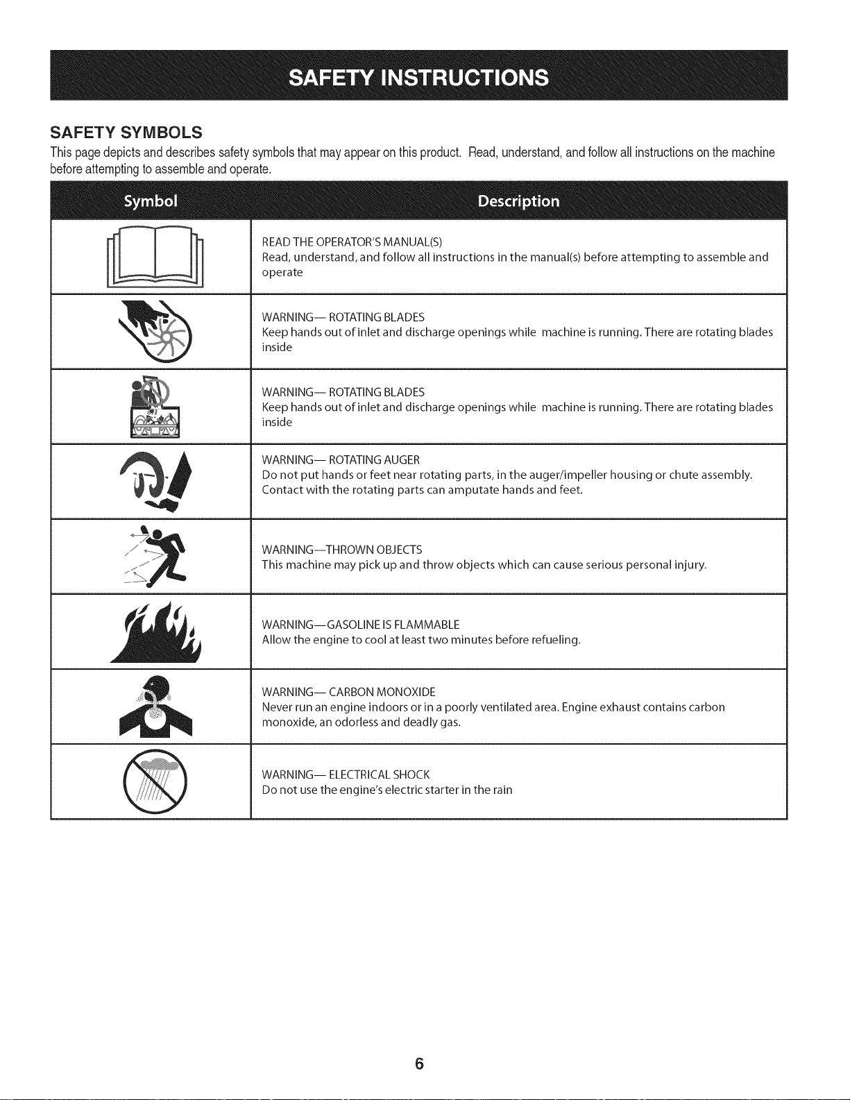
SAFETY SYMBOLS
Thispagedepictsanddescribessafetysymbolsthatmayappearonthisproduct. Read,understand,andfollowall instructionson themachine
beforeattemptingto assembleandoperate.
READ THE OPERATOR'S MANUAL(S)
i
. +
i
Read, understand, and follow all instructions in the manual(s) before attempting to assemble and
operate
WARNING-- ROTATING BLADES
Keep hands out of inlet and discharge openings while machine is running. There are rotating blades
inside
WARNING-- ROTATING BLADES
Keep hands out of inlet and discharge openings while machine is running. There are rotating blades
inside
WARNING-- ROTATING AUGER
Do not put hands or feet near rotating parts, in the auger/impeller housing or chute assembly.
Contact with the rotating parts can amputate hands and feet.
"JIp
WARNING--THROWN OBJECTS
This machine may pick up and throw objects which can cause serious personal injury.
WARNING--GASOLINE ISFLAMMABLE
Allow the engine to cool at least two minutes before refueling.
WARNING-- CARBON MONOXIDE
Never run an engine indoors or in a poorly ventilated area. Engine exhaust contains carbon
monoxide, an odorless and deadly gas+
WARNING-- ELECTRICAL SHOCK
Do not use the engine's electric starter in the rain
6

Thispageleftintentionallyblank.
7

NOTE:Referencesto rightorleft sideof the snowthrowerare
determinedfrombehindtheunitinthe operatingposition(standing
directlybehindthesnowthrower,facingthe handlepanel).
REMOVING FROM CARTON
1. Cutthecornersofthecartonandlay the sidesflaton the ground.
Removeanddiscardallpackinginserts.
2. Movethesnowthroweroutofthecarton.
3. Makecertainthecartonhasbeencompletelyemptiedbefore
discardingit.
LOOSE PARTS
Tworeplacementaugershearpinsare includedinthehandlepanel.
RefertoReplacingShearPinsinthe Operationsectionfor more
informationregardingshearpin replacement.
ASSEMBLY
1. Placethe shiftleverin the Forward-6position.
2. Observethe lowerrearareaof the snowthrowerto besureboth
cablesarealignedwith rollerguidesbeforepivotingthehandle
upward.See Figure1.
Figure1
NOTE:Makecertainthe upperends of eachcableareseatedproperly
in itsbracket.
.
Securethehandlebytighteningthe plasticwingknoblocatedon
boththe left andrightsidesofthehandle.SeeFigure2. Remove
anddiscardanyrubberbands,ifpresent.Theyareforpackaging
purposesonly.
f
!
/
/
/
Figure2
8
.
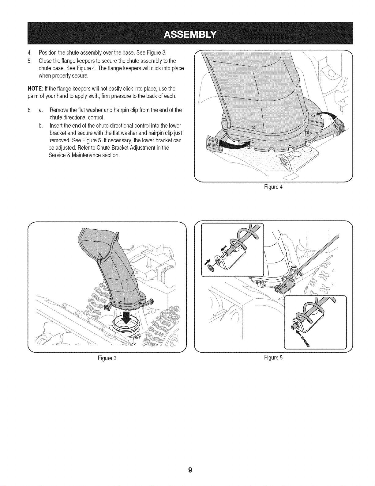
Positionthechuteassemblyoverthebase.See Figure3.
5.
Closetheflangekeepersto securethechuteassemblytothe
chutebase.SeeFigure4.The flangekeeperswill click intoplace
whenproperlysecure.
NOTE:Iftheflangekeeperswill noteasilyclickintoplace,usethe
palmof yourhandto applyswift,firmpressuretothebackofeach.
.
a.
Removetheflatwasherand hairpinclipfromtheendof the
chutedirectionalcontrol.
b.
Insertthe endofthechutedirectionalcontrolintothelower
bracketandsecurewiththeflatwasherandhairpinclipjust
removed.See Figure5.If necessary,the lowerbracketcan
beadjusted.Referto ChuteBracketAdjustmentinthe
Service& Maintenancesection.
f F
Figure4
Figure3
\
J
Figure5
9
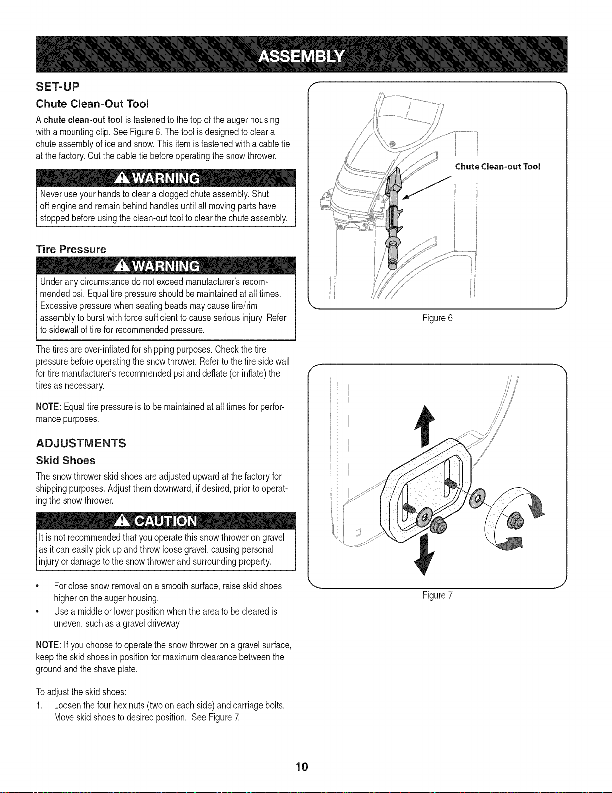
SET-UP
Chute Clean-Out Tool
Achute clean-out tool isfastenedtothe top of the augerhousing
witha mountingclip.SeeFigure6.Thetoolisdesignedtocleara
chuteassemblyoficeandsnow.Thisitemisfastenedwitha cabletie
atthefactory.Cutthecabletiebeforeoperatingthe snowthrower.
Neveruseyour handsto cleara cloggedchuteassembly.Shut
offengineand remainbehindhandlesuntilall movingpartshave
stoppedbeforeusingtheclean-outtooltoclearthechuteassembly.
Tire Pressure
Underanycircumstancedo notexceedmanufacturer'srecom-
mendedpsi.Equaltirepressureshouldbemaintainedatall times.
Excessivepressurewhenseatingbeadsmaycausetire/rim
assemblytoburstwithforcesufficienttocauseseriousinjury.Refer
tosidewallof tirefor recommendedpressure.
Thetiresareover-inflatedforshippingpurposes.Checkthetire
pressurebeforeoperatingthe snowthrower.Referto the tire sidewall
fortiremanufacturer'srecommendedpsianddeflate(or inflate)the
tiresasnecessary.
ChuteClean-outTool
Figure6
f
NOTE:Equaltire pressureistobe maintainedat alltimesforperfor-
mancepurposes.
ADJUSTMENTS
Skid Shoes
Thesnowthrowerskidshoesareadjustedupwardatthefactoryfor
shippingpurposes.Adjustthemdownward,ifdesired,priorto operat-
ingthesnowthrower.
It is not recommendedthatyouoperatethissnowthrowerongravel
asitcaneasilypickup andthrowloosegravel,causingpersonal
njuryordamageto the snowthrowerandsurroundng property.
• Forclosesnowremovalona smoothsurface,raiseskidshoes
higherontheaugerhousing.
• Usea middleorlowerpositionwhentheareatobe clearedis
uneven,suchas a graveldriveway
NOTE:If youchoosetooperatethesnowthrowerona gravelsurface,
keepthe skidshoesin positionfor maximumclearancebetweenthe
groundandtheshaveplate.
Toadjustthe skidshoes:
1. Loosenthefourhexnuts(twooneachside)andcarriagebolts.
Moveskidshoestodesiredposition. SeeFigure7.
Figure7
10

2, Makecertaintheentirebottomsurfaceof skidshoeisagainstthe f
groundtoavoidunevenwearontheskidshoes, ....
3, Refightennutsandboltssecurely,
Chute Assembly
Thedistancesnowisthrowncanbeadjustedbychangingtheangleof
thechuteassembly,Todo so:
1, Stopthe engineby removingtheignitionkeyandloosenthe
plasticwingknobfoundonthe left sideofthechuteassembly.
2, Pivotthechuteupwardordownwardbeforeretighteningthewing
knob,See Figure8,
Auger Control
Priortooperatingyoursnowthrower,carefullyreadandfollowall
instructionsbelow,Performalladjustmentsto verifyyoursnow
throwerisoperatingsafelyand properly,
Checktheadjustmentof the augercontrolas follows:
1. Whentheaugercontrolis releasedandin thedisengaged"up"
position,thecableshouldhaveverylittleslack.ItshouldNOTbe
tight.
2. Ina well-ventilatedarea,startthesnowthrowerengine.Referto
StartingtheEngineintheOperationsection.
3. Whilestandingintheoperator'sposition(behindthe snow
thrower),engagethe auger.
4. Allowtheaugerto remainengagedforapproximatelyten(10)
secondsbeforereleasingthe augercontrol.Repeatthisseveral
times.
5. Withtheaugercontrolin thedisengaged"up"position,walktothe
frontofthemachine.
6. Confirmthatthe augerhas completelystoppedrotatingand
showsNOsignsof motion.If the augershowsANYsignsof
rotating,immediatelyreturntotheoperator'spositionandshutoff
theengine.WaitforALLmovingpartsto stopbeforeadjustingthe
augercontrol.
7. Toreadjustthecontrolcable,loosentheupperhexboltonthe
augercablebracket.SeeFigure9.
8. Positionthe bracketupwardtoprovidemoreslack(or downward
toincreasecabletension).
9. Retightentheupperhexbolt.
10. Repeatsteps2-6aboveto verifyproperadjustmenthasbeen
achieved.
Figure8
11
f
Drive Control
Shift Lever
J
J
Gas Cap
ChuteAssembly OilFill
\ \,
Clean Out
\
\
Tool
\
Augers
Skid Shoe
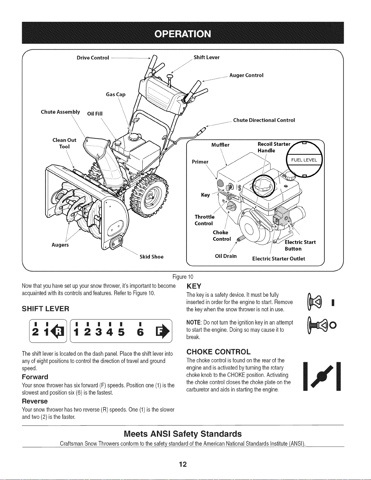
Nowthat youhavesetup yoursnowthrower,it'simportanttobecome
acquaintedwith itscontrolsandfeatures.Referto Figure10.
SHIFT LEVER
Auger Control
j_. ChuteDirectionalControl
Mumer Recoil Starter
Primer
Key
Throttle
Control
Choke
Control
Oil Drain
,.. j
_.Handle
Electric Starter Outlet
Figure10
KEY
Thekeyisa safetydevice.It mustbefully
insertedin orderfor the engineto start. Remove
thekeywhenthesnowthroweris not in use.
:lectric Start
Button
J
1 2345 6
'
Theshiftleverislocatedonthe dash panel.Placetheshiftleverinto
anyof eight positionstocontrolthedirectionoftravelandground
speed.
Forward
Yoursnowthrowerhassixforward(F)speeds.Positionone(1)is the
slowestandpositionsix(6) isthefastest.
Reverse
Yoursnowthrowerhastwo reverse(R) speeds.One(1)is the slower
andtwo(2) isthefaster.
Meets ANSI Safety Standards
CraftsmanSnowThrowersconformto the safetystandardoftheAmericanNationalStandardsInstitute(ANSI).
NOTE:Donot turntheignitionkeyinan attempt
to starttheengine.Doingso maycauseitto
break.
CHOKE CONTROL
Thechokecontrolisfoundon therearofthe
engineand is activatedbyturningthe rotary
chokeknobtothe CHOKEposition.Activating
thechokecontrolclosesthe chokeplateonthe
carburetorandaids in startingtheengine.
12
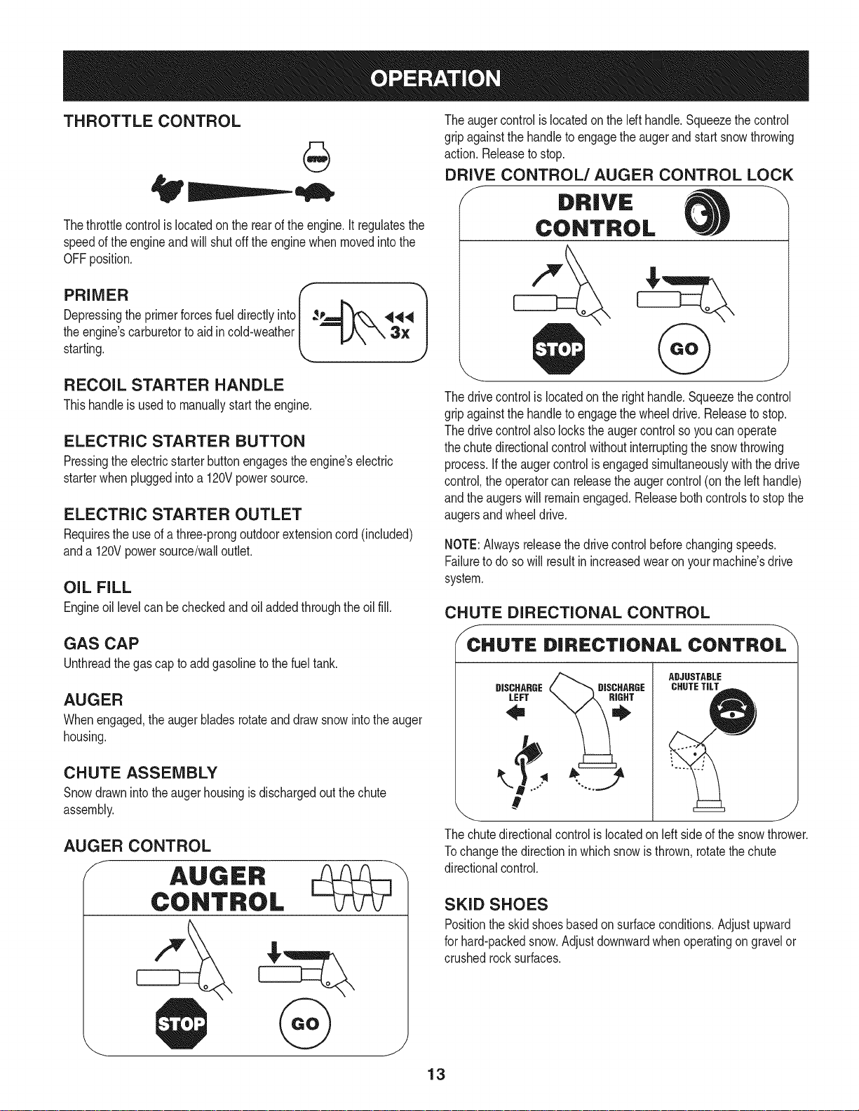
THROTTLE CONTROL
aiW'
Theaugercontrolislocatedon thelefthandle.Squeezethe control
gripagainstthehandletoengagetheaugerand startsnowthrowing
action.Releaseto stop.
DRIVE CONTROL/AUGER CONTROL LOCK
J DRIVE
Thethrottlecontrolis locatedonthe rearof the engine.It regulatesthe
speedof theengineandwill shutoff theenginewhenmovedintothe
OFFposition.
Depressingthe primerforcesfuel directlyinto ___144
theengine'scarburet°rt° aid inc°'dweather k _"_'-_ 3" Jstarting.
RECOIL STARTER HANDLE
Thishandleisusedto manuallystarttheengine.
ELECTRIC STARTER BUTTON
Pressingtheelectricstarterbuttonengagestheengine'selectric
starterwhenpluggedintoa120Vpowersource.
ELECTRIC STARTER OUTLET
Requirestheuseof athree-prongoutdoorextensioncord(included)
anda 120Vpowersource/walloutlet.
OIL FILL
Engineoil levelcanbecheckedandoiladdedthroughtheoil fill.
r 1
CONTROL
Thedrivecontrolis locatedon the righthandle.Squeezethe control
gripagainstthehandletoengagethewheeldrive.Releaseto stop.
Thedrivecontrolalso lockstheaugercontrolsoyoucan operate
thechutedirectionalcontrolwithoutinterruptingthesnowthrowing
process.If theaugercontrolisengagedsimultaneouslywiththe drive
control,the operatorcanreleasetheaugercontrol(onthelefthandle)
andtheaugerswillremainengaged.Releaseboth controlstostopthe
augersandwheeldrive.
NOTE:Alwaysreleasethedrivecontrolbeforechangingspeeds.
Failureto dosowill resultinincreasedwearonyourmachine'sdrive
system.
CHUTE DIRECTIONAL CONTROL
GAS CAP
Unthreadthegascaptoaddgasolinetothe fuel tank.
AUGER
Whenengaged,theaugerbladesrotateand drawsnowintotheauger
housing.
CHUTE ASSEMBLY
Snowdrawnintotheaugerhousingisdischargedout the chute
assembly.
AUGER CONTROL
/_CCHUTE DIRECTIONAL CONTROL
LEFT
DISCHARGE CHUTETILTDISCHARGE
#
_ J
The chute directionalcontrol is located on left side of the snow thrower.
Tochange the direction inwhich snow is thrown, rotate the chute
directionalcontrol.
SKID SHOES
Positiontheskidshoesbasedonsurfaceconditions.Adjustupward
forhard-packedsnow.Adjustdownwardwhenoperatingon gravelor
crushedrocksurfaces.
ADJUSTABLE
13

CLEAN-OUT TOOL
Neveruseyourhandsto cleara cloggedchuteassembly.Shut
off engineandremainbehindhandlesuntilall movingpartshave
stoppedbeforeusingtheclean-outtoolto clear thechuteassembly.
Thechuteclean-outtoolisconvenientlyfastenedtothe rearofthe
augerhousingwitha mountingclip. Shouldsnowandicebecome
lodgedin thechuteassemblyduringoperation,proceedasfollowsto
safelycleanthechuteassemblyandchuteopening:
1. Releaseboththe AugerControlandtheDriveControl.
2. Stopthe engineby removingtheignitionkey.
3. Removetheclean-outtoolfromtheclipwhichsecuresit to the
rearoftheaugerhousing.
4. Usetheshovel-shapedendof theclean-outtoolto dislodgeand
scoopanysnowand icewhichhasformedin andnearthechute
assembly.
5. Refastenthe clean-outtooltothemountingclip ontherearof
theaugerhousing,reinserttheignitionkeyandstartthesnow
thrower'sengine.
6. Whilestandingintheoperator'sposition(behindthesnow
thrower),engagethe augercontrolfora fewsecondstoclear any
remainingsnowandice fromthechuteassembly.
BEFORE STARTING ENGINE
Read,understand,andfollowall instructionsandwarningsonthe
machineand inthismanualbeforeoperating.
Oil
Theunit wasshippedwith oil inthe engine.Checkoil levelbefore
eachoperationtoensureadequateoil intheengine.Forfurther
instructions,refertothe stepson page16.
NOTE:Besureto checktheengineon alevelsurfacewiththeengine
stopped.
1. Removetheoil fillercap/dipstickandwipethedipstickclean.
2. insertthecap/dipstickintothe oilfillerneck,butdo NOTscrewit
in.
3. Removetheoil fillercap/dipstick,ifthelevelislow,slowlyadd
oil (5%30, witha minimumclassificationof SF/SG)untiloil level
registersbetweenhigh(H) andlow(L).
NOTE:Do notoverfill.Overfillingwithoil mayresultinenginesmoking,
hardstartingorsparkplugfouling.
4. Replaceandtightencap/dipstickfirmlybeforestartingengine.
Gasoline
Useautomotivegasoline(unleadedor low leadedto minimizecombus-
tionchamberdeposits)witha minimumof87octane.Gasolinewith
upto 10%ethanolor 15%MTBE(MethylTertiaryButylEther)canbe
used.Neveruseanoil/gasolinemixtureordirtygasoline.Avoidgetting
dirt,dust,or waterinthefueltank.DONOTuseE85gasoline.
• Refuelina well-ventilatedareawiththe enginestopped.Donot
smokeorallowflamesor sparksinthe areawheretheengineis
refueledor wheregasolineisstored.
• Donotoverfillthe fueltank.After refueling,makesurethetank
capisclosedproperlyandsecurely.
• Becarefulnotto spillfuelwhenrefueling.Spilledfuelorfuel vapor
mayignite,ifany fuelisspilled,makesuretheareaisdry before
startingthe engine.
• Avoidrepeatedorprolongedcontactwithskinor breathingof
)or.
Useextremecarewhenhandlinggasoline.Gasolineisextremely
flammableandthevaporsare explosive.Neverfuelthemachine
indoorsorwhiletheengineishotor running.Extinguishcigarettes,
cigars,pipesandothersourcesof ignition.
1. Cleanaroundfuel fill beforeremovingcaptofuel.
2. A fuellevelindicatorislocatedinthe fueltank.SeeFigure10
inset.Becarefulnottooverfill.Filltank untilfuel reachesthefuel
levelindicatortoallowspaceforfuelexpansion.
STARTING THE ENGINE
Alwayskeephandsandfeetclearof movingparts.Donot usea
pressurizedstartingfluid.Vaporsareflammable.
NOTE:Allowtheenginetowarmupfor a fewminutesafter starting.
Theenginewillnotdevelopfullpoweruntilitreachesoperating
temperatures.
1. Makecertainboththe augercontrolanddrivecontrolarein the
disengaged(released)position.
2. insertkeyintoslot.Makesureit snapsintoplace.Donot attempt
toturnthekey.
NOTE:Theenginecannotstartwithoutthekeyfullyinsertedintothe
ignitionswitch.
Electric Starter
Theoptionalelectricstarteris equippedwitha groundedthree-wire
powercordand plug,andis designedtooperateon 120voltAC
householdcurrent.Itmustbe usedwitha properlygroundedthree-
prongreceptacleat all timestoavoidthepossibilityofelectricshock.
Followall instructionscarefullypriortooperatingtheelectricstarter.
DONOTuseelectricstarterinthe rain.
Determinethatyourhome'swiringisa three-wiregroundedsystem.
Aska licensedelectricianifyouarenotcertain.
Ifyou havea groundedthree-prongreceptacle,proceedasfollows.
Ifyou donothavethe properhousewiring,DONOTusethe electric
starterunderanyconditions.
1. Plugtheextensioncord intotheoutletlocatedon the engine's
surface.Plugtheotherendof extensioncord intoa three-prong
120-volt,grounded,ACoutletina well-ventilatedarea.
14

2. Movethrottlecontrolto FAST(rabbit)_T position.
3. MovechoketotheCHOKEIJl position(coldenginestart).If
engineiswarm,placechokein RUNposition.
4. Pushprimerthree(3)times,makingsuretocoverventholein
primerbulbwhen pushing.Ifengineiswarm,pushprimeronly
once.Alwayscoverventholewhenpushing.Coolweathermay
requireprimingtobe repeated.
5. Pushstarterbuttontostartengine.Oncetheenginestarts,im-
mediatelyreleasestarterbutton.Electricstarteris equippedwith
thermaloverloadprotection;systemwilltemporarilyshut-downto
allowstartertocoolifelectricstarterbecomesoverloaded.
6. Astheenginewarms,slowlyrotatethechokecontrolto RUN
position.Iftheenginefalters,restartengineandrunwithchoke
athalf-chokepositionfor a shortperiodoftime,andthenslowly
rotatethechokeintoRUNposition.
7. Afterengineisrunning,disconnectpowercordfromelectric
starter.Whendisconnecting,alwaysunplugtheendatthewall
outletbeforeunpluggingtheoppositeendfromtheengine.
Recoil Starter
Donotpullthestarterhandlewhiletheenginerunning.
1. Movethrottlecontrolto FAST(rabbit)_J_ position.
2. MovechoketotheCHOKEI,'_¢1position(coldenginestart).If
engineiswarm,placechokein RUNposition.
3. Pushprimerthree(3)times,makingsuretocoverventholewhen
pushing.Ifengineiswarm,push primeronlyonce.Alwayscover
ventholewhenpushing.Coolweathermayrequireprimingtobe
repeated.
4. Pullgentlyonthe starterhandleuntil it beginstoresist,then
pullquicklyandforcefullyto overcomethecompression.Do
notreleasethehandleandallowitto snapback.Returnrope
SLOWLYto originalposition.Ifrequired,repeatthisstep.
5. Astheenginewarms,slowlyrotatethechokecontrolto RUN
position.Iftheenginefalters,restartengineandrunwithchoke
athalf-chokepositionfor a shortperiodoftime,andthenslowly
rotatethechokeintoRUNposition.
TO ENGAGE DRIVE
1. Withthethrottlecontrolinthe Fast(rabbit)'_ position,move
shiftleverintooneof thesix forward(F) positionsortwo reverse
(R)positions.Selecta speedappropriateforthesnowconditions
anda paceyou'recomfortablewith.
NOTE:Whenselectinga DriveSpeed,usetheslowerspeedsuntil
youarecomfortableandfamiliarwiththeoperationofthesnow
thrower.
2. Squeezethedrivecontrolagainstthe handleandthesnow
throwerwillmove.Releaseitanddrive motionwillstop.
NOTE:NEVERrepositionthe shiftlever(changespeedsordirection
oftravel)withoutfirst releasingthedrivecontrolandbringingthesnow
throwertoa completestop.Doingsowill resultin prematurewearto
thesnowthrower'sdrivesystem.
TO ENGAGE AUGER
1. Toengagethe augerand startthrowingsnow,squeezetheauger
controlagainsttheleft handle.Releasetostopthe auger.
REPLACING SHEAR PINS
Eachaugerbladeissecuredtothespiralshaftwitha shearpinand
bow-tieclip. Ifanaugerbladestrikesa foreignobjector icejam,the
pinwillshearoff topreventdamagetotheblade.Ifanaugerblade
doesnotturn,checkto see if its pinhasshearedoff.SeeFigure11.
NEVERreplacethe augershearpinswithanythingotherthanSears
SKU#88389/0EMPartNo.738-04124Areplacementshearpins.
Anydamagetotheaugergearboxorothercomponentsas a resultof
[fang to dosow NOTbecoveredbyyoursnowthrowerswarranty.
Alwaysturnoff the snowthrower'sengineandremovethekeypriorto
replacingshearpins.
Toavoid unsupervisedengineoperation,neverleavethemachine
unattendedwiththeenginerunning.Turntheengineoffafteruseand
removekey.
STOPPING THE ENGINE
Afteryouhavefinishedsnow-throwing,runenginefora few minutes
beforestoppingtohelpdryoffany moistureontheengine.
1. Movethrottlecontrolto OFFposition.
2. Removethekey.Removingthe keywill reducethepossibilityof
unauthorizedstartingoftheenginewhileequipmentisnotin use.
Keepthekeyina safeplace.Theenginecannotstartwithoutthe
key.
3. Wipeanymoistureawayfromthe controlson theengine.
15
iJ
Figure11
s ¸......
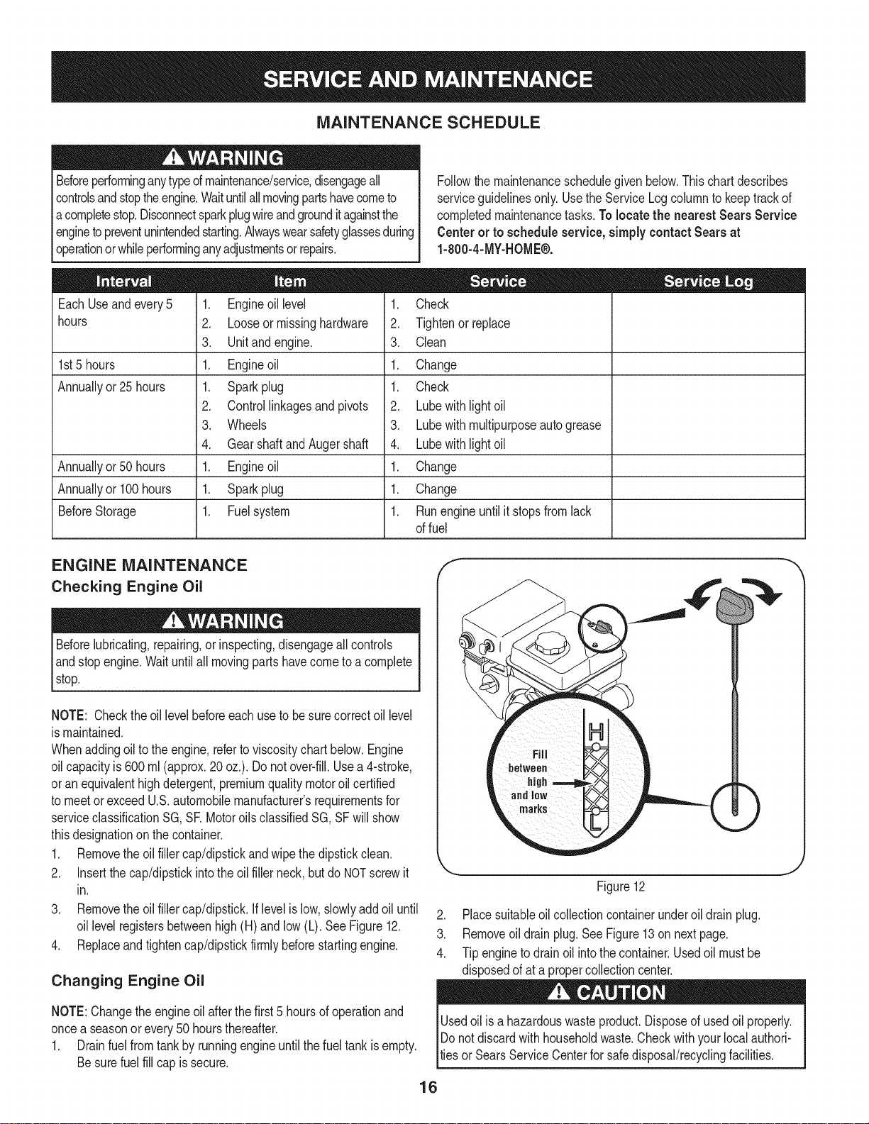
MAINTENANCE SCHEDULE
Beforeperforminganytypeofmaintenance/service,disengageall
controlsandstoptheengine.Waituntilallmovingpartshavecometo
acompletestop.Disconnectsparkplugwireandgrounditagainstthe
enginetopreventunintendedstarting.Alwayswearsafetyglassesduring
operationorwhileperforminganyadjustmentsorrepairs.
EachUseandevery5
hours
1st5 hours
Annuallyor25 hours
Annuallyor50 hours
Annuallyor100hours
BeforeStorage
1. Engineoil level
2. Looseor missinghardware
3. Unitand engine.
1. Engineoil
1. Sparkplug
2. Controllinkagesandpivots
3. Wheels
4. GearshaftandAugershaft
1. Engineoil
1. Sparkplug
1. Fuelsystem
1. Check
2. Tightenor replace
3. Clean
1. Change
1. Check
2. Lubewithlightoil
3. Lubewithmultipurposeautogrease
4. Lubewithlightoil
1. Change
1. Change
1. Runengineuntilit stopsfromlack
ENGINE MAINTENANCE
Checking Engine Oil
Followthemaintenanceschedulegivenbelow.Thischartdescribes
serviceguidelinesonly.Usethe ServiceLogcolumntokeeptrackof
completedmaintenancetasks.Tolocate the nearest SearsService
Centeror to scheduleservice,simplycontactSearsat
1-800-4-MY-HOME®.
offuel
f
Beforelubricating,repairing,or inspecting,disengageall controls
Iandstopengine.Waituntilall movingpartshavecometo acomplete
_stop.
NOTE: Checktheoil levelbeforeeachuseto besurecorrectoil level
ismaintained.
Whenaddingoiltotheengine,referto viscositychart below.Engine
oilcapacityis 600ml (approx.20oz.).Donot over-fill.Usea 4-stroke,
oran equivalenthighdetergent,premiumqualitymotoroilcertified
tomeetorexceedU.S.automobilemanufacturer'srequirementsfor
serviceclassificationSG, SR MotoroilsclassifiedSG,SFwillshow
thisdesignationonthecontainer.
1. Removetheoil fillercap/dipstickandwipethedipstickclean.
2. Insertthe cap/dipstickintotheoilfiller neck,butdo NOTscrewit
in.
3. Removetheoil fillercap/dipstick.Iflevelis low,slowlyaddoiluntil
oil levelregistersbetweenhigh(H)andlow (L). SeeFigure12.
4. Replaceandtightencap/dipstickfirmlybeforestartingengine.
Changing Engine Oil
NOTE:Changetheengineoilafterthefirst5 hoursof operationand
oncea seasonorevery50 hoursthereafter.
1. Drainfuelfromtankbyrunningengineuntilthe fuel tankisempty.
Besurefuelfill capis secure.
1 •
_i!_!iiii_ii!i!jili iiiIiiiii_H
marks
Figure12
2. Placesuitableoilcollectioncontainerunderoil drainplug.
3. Removeoil drainplug.SeeFigure13on nextpage.
4. Tipenginetodrainoil intothe container.Usedoil mustbe
disposedofata propercollectioncenter.
Usedoil isa hazardouswasteproduct.Disposeofusedoil properly.
IDo notdiscardwithhouseholdwaste.Checkwithyourlocalauthori-
lties or SearsServiceCenterforsafedisposal/recyclingfacilities.
16
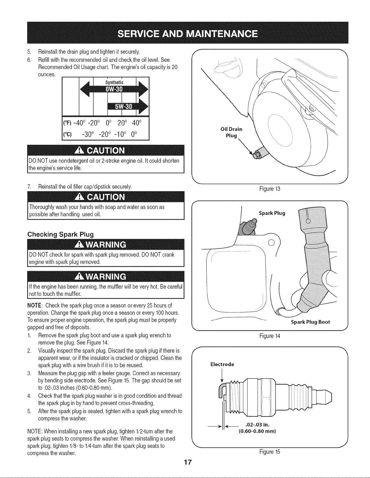
.
Reinstallthedrainplugandtightenit securely.
6.
Refillwiththerecommendedoilandchecktheoil level.See
RecommendedOil Usagechart.Theengine'soilcapacityis20
ounces.
(%-400 -200 0o 200 400
("c) -300 -200 -10° 0°
DONOTuse nondetergentoilor 2-strokeengineoil.Itcouldshorten
theengine'sservicelife.
Oil Drain
Plug
7. Reinstalltheoilfillercap/dipsticksecurely.
afterhandling usedoil.
Checking Spark Plug
DONOTcheckfor sparkwithsparkplugremoved.DONOTcrank
enginewithsparkplugremoved.
Iftheenginehasbeenrunning,themufflerwillbevery hot.Becareful
notto touchthemuffler.
NOTE: Checkthesparkplugoncea seasonorevery25hoursof
operation.Changethesparkplugoncea seasonor every100hours.
Toensureproperengineoperation,thesparkplugmustbe properly
gappedandfreeofdeposits.
1. Removethesparkplugbootandusea sparkplugwrenchto
removetheplug.See Figure14.
2. Visuallyinspectthesparkplug.Discardthesparkplugifthereis
apparentwear,orif the insulatoriscrackedorchipped.Cleanthe
sparkplugwitha wirebrush if it is to bereused.
3. Measurethe pluggapwitha feelergauge.Correctas necessary
bybendingsideelectrode.SeeFigure15.Thegapshouldbeset
to.02-.03inches(0.60-0.80ram).
4. Checkthatthe sparkplugwasherisingoodconditionandthread
thesparkplugin byhandto preventcross-threading.
5. Afterthesparkplugis seated,tightenwitha sparkplugwrenchto
compressthewasher.
NOTE:Wheninstallinga newsparkplug,tighten1/2-turnafterthe
sparkplugseatstocompressthewasher.Whenreinstallinga used
sparkplug,tighten1/8-to 1/4-turnafterthesparkplugseatsto
compressthewasher.
Figure13
Spark Plug
O
J
Figure14
Electrode
.02-.03 in.
{0.60-0.80 ram)
Figure15
17

become hotandcan inc.
LUBRICATION
Gear Shaft
Thegear(hex)shaft shouldbe lubricatedatleastoncea seasonor
afterevery25 hoursofoperation.
1. Topreventspillage,removeall fuelfromtank byrunningengine
untilitstops.
2. Carefullypivotthesnowthrowerupandforwardsothat it restson
theaugerhousing.
3. Removethe lowerframecoverfromthe undersideofthesnow
throwerbyremovingtheself-tappingscrewswhichsecureit.
4. Applya lightcoatingofengineoil (or3-in-1oil) to the hexshaft.
SeeFigure16.
NOTE:Whenlubricatingthehexshaft,be carefulnottogetanyoilon
thealuminumdriveplateor rubberfrictionwheel.Doingsowillhinder
thesnowthrower'sdrivesystem.Wipeoff anyexcessor spilledoil.
Wheels
Atleastoncea season,removebothwheels.Cleanandcoattheaxles
witha multipurposeautomotivegreasebeforereinstallingwheels.
Chute Directional Control
Oncea season,lubricatetheeyeboltbushingand thespiralwith3-in-1
oil.
Figure16
f
Auger Shaft
Atleastoncea season,removetheshearpinson augershaft.Spray
lubricantinsideshaft,andaroundthespacersandflangebearings
foundat eitherendof theshaft.SeeFigure17.
SHAVE PLATE AND SKID SHOES
Theshaveplateandskidshoesonthebottomofthesnowthrowerare
subjecttowear.Theyshouldbecheckedperiodicallyandreplaced
whennecessary.
NOTE:Theskidshoeson thismachinehavetwowearedges.When
onesidewearsout,theycanbe rotated1800to usetheotheredge.
Toremoveskidshoes:
1. Removethetwocarriagebolts,washers,andhexflangenutsthat
secureeachskidshoeto the snowthrower.
2. Reassemblenewskidshoeswiththe fourcarriagebolts(twoon
eachside),washers,andhex flangenuts.RefertoFigure18.
Toremoveshaveplate:
1. Removethecarriageboltsand hexnutswhichattachit tothe
snowthrowerhousing.
2. Reassemblenewshaveplate,makingsureheadsofcarriage
boltsareto the insideof housing.Tightensecurely.SeeFigure18.
Figure17
NOTE:Augers not shown for clarity.
/
/
/
/
18
Figure18
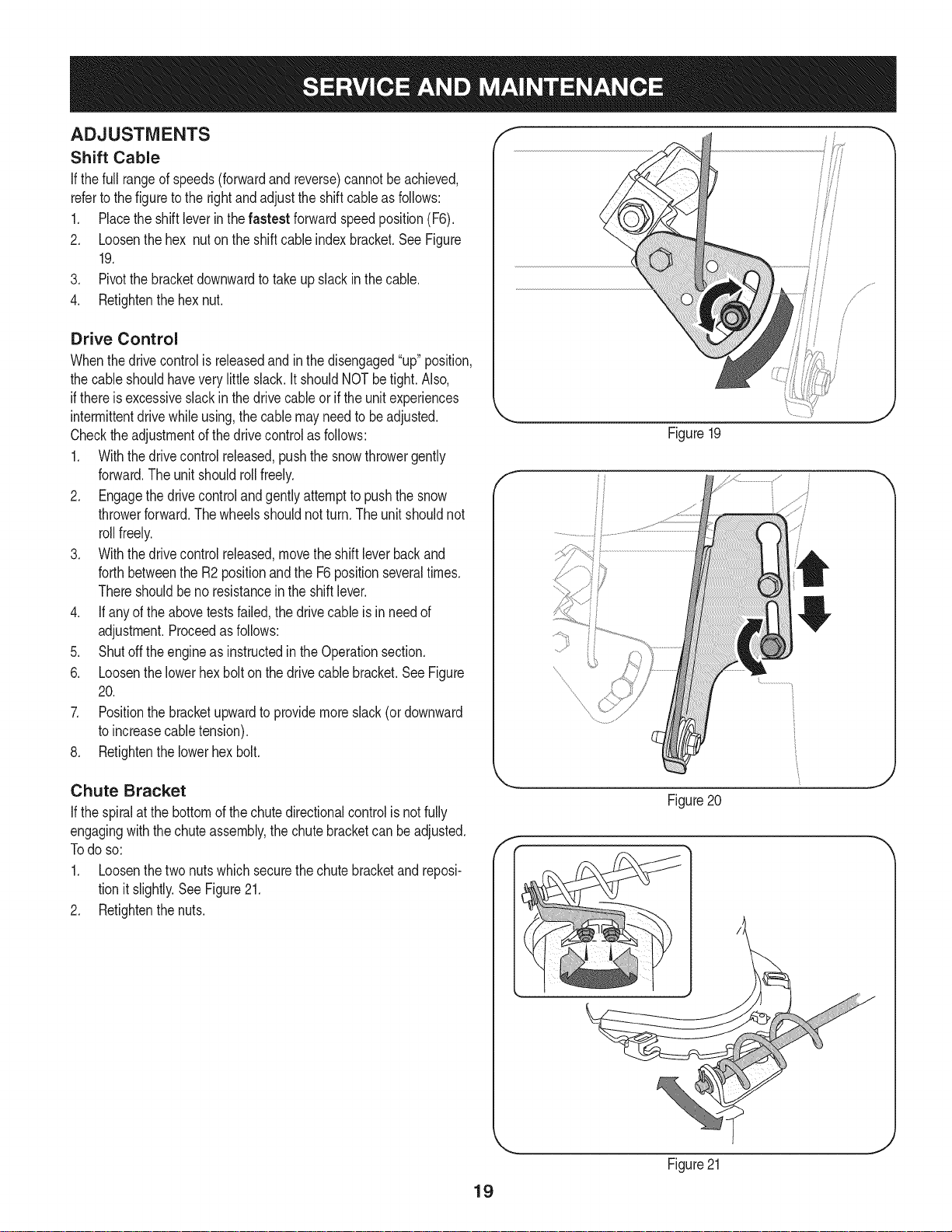
ADJUSTMENTS
Shift Cable
If thefull rangeofspeeds(forwardandreverse)cannotbeachieved,
referto the figuretotherightandadjusttheshiftcableas follows:
1. Placethe shiftleverinthefastest forwardspeedposition(F6).
2. Loosenthehex nuton theshiftcableindexbracket.SeeFigure
19.
3. Pivotthebracketdownwardto takeupslackinthe cable.
4. Retightenthehexnut.
Drive Control
Whenthedrivecontrolisreleasedandin thedisengaged"up"position,
thecableshouldhaveverylittle slack.It shouldNOTbetight.Also,
ifthereis excessiveslackin thedrivecableor iftheunitexperiences
intermittentdrivewhileusing,thecable mayneedtobeadjusted.
Checktheadjustmentof the drivecontrolasfollows:
1. Withthedrivecontrolreleased,pushthesnowthrowergently
forward.Theunitshouldrollfreely.
2. Engagethe drivecontrolandgentlyattemptto pushthesnow
throwerforward.Thewheelsshouldnotturn.Theunitshouldnot
rollfreely.
3. Withthedrivecontrolreleased,movetheshiftleverbackand
forthbetweenthe R2positionandtheF6positionseveraltimes.
Thereshouldbeno resistancein the shiftlever.
4. If anyoftheabovetestsfailed,thedrivecable is in needof
adjustment.Proceedasfollows:
5. Shutoff theengineas instructedintheOperationsection.
6. Loosenthelowerhexbolt onthedrivecable bracket.SeeFigure
20.
7. Positionthe bracketupwardtoprovidemoreslack(or downward
toincreasecabletension).
8. Retightenthelowerhex bolt.
Figure19
f
Chute Bracket
If the spiralatthe bottomofthechutedirectionalcontrolisnotfully
engagingwiththe chuteassembly,thechutebracketcanbeadjusted.
Todo so:
1. Loosenthetwonutswhichsecurethechutebracketandreposi-
tionitslightly.See Figure21.
2. Retightenthenuts.
Figure20
f
Figure21
19

Auger Control f "_
RefertotheAssemblysectionforinstructionsonadjustingtheauger
controlcable.
Skid Shoes
RefertotheAssemblysectionforinstructionsonadjustingtheskid
shoes.
BELT REPLACEMENT
Auger Belt
Toremoveandreplaceyoursnowthrower'saugerbelt,proceedas
follows:
1. Topreventspillage,removeall fuelfromtank byrunningengine
untilitstops.
2. Removethe plasticbeltcoveronthe frontoftheenginebyremov-
ingthetwoself-tappingscrews.SeeFigure22.
3. Rolltheaugerbeltoff theenginepulley.See Figure23.
4. Carefullypivotthesnowthrowerupandforwardsothat itrestson
theaugerhousing.
5. Removetheframecoverfromtheundersideofthesnowthrower
byremovingfourself-tappingscrewswhichsecureit.SeeFigure
24.
Figure22
f
J
2O
Figure 23
f
//
J
Figure24
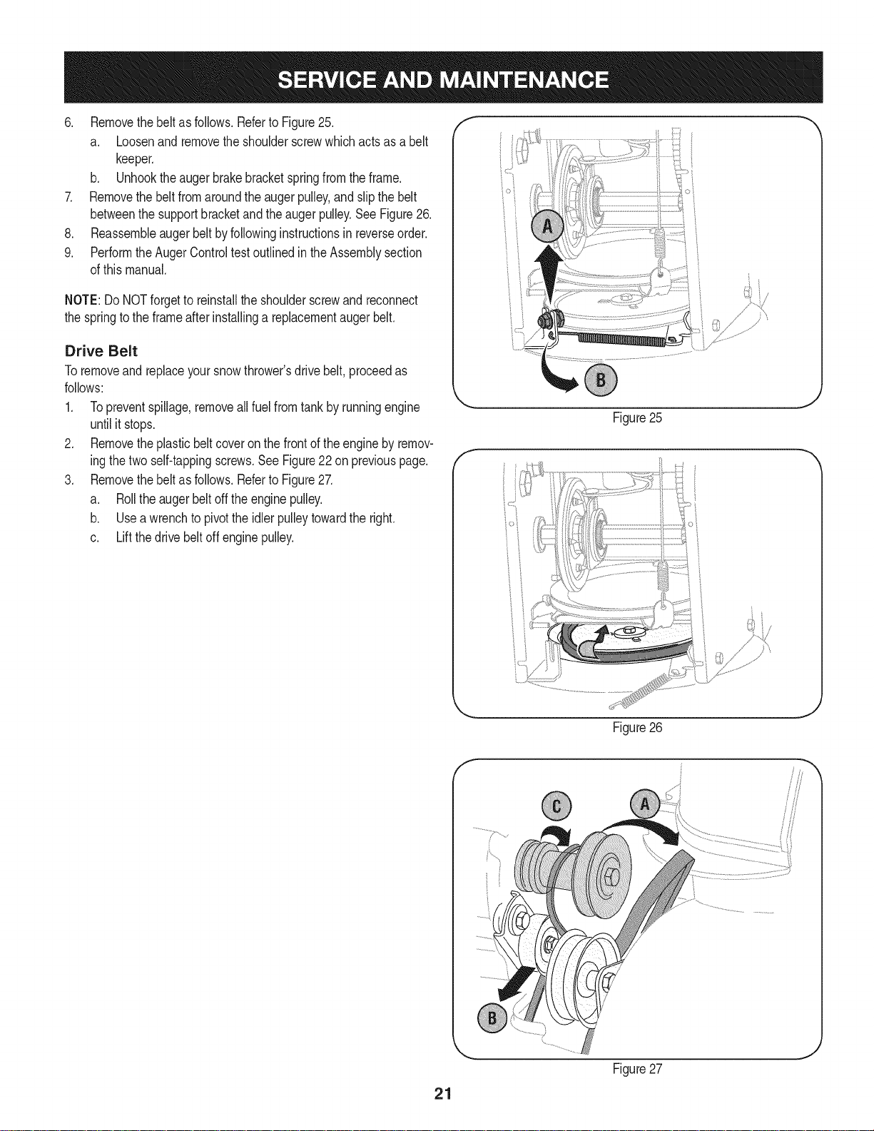
6. Removethebeltasfollows.RefertoFigure25.
a. Loosenandremovetheshoulderscrewwhichactsasabelt
keeper.
b. Unhooktheaugerbrakebracketspringfromtheframe.
7. Removethebeltfromaroundtheaugerpulley,andslipthebelt
betweenthesupportbracketandtheaugerpulley.SeeFigure26.
8. Reassembleaugerbeltbyfollowinginstructionsinreverseorder.
9. PerformtheAugerControltestoutlinedintheAssemblysection
ofthismanual.
NOTE:DoNOTforgettoreinstalltheshoulderscrewandreconnect
thespringtotheframeafterinstallingareplacementaugerbelt.
Drive Belt
Toremoveandreplaceyoursnowthrower'sdrivebelt,proceedas
follows:
1. Topreventspillage,removeallfuel fromtankby runningengine
untilit stops.
2. Removetheplasticbelt coveronthefrontoftheenginebyremov-
ingthetwoself-tappingscrews.SeeFigure22on previouspage.
3. Removethebeltasfollows.RefertoFigure27.
a. Rolltheaugerbeltoff theenginepulley.
b. Useawrenchto pivottheidlerpulleytowardthe right.
c. Liftthedrivebelt off enginepulley.
Figure25
21
Figure26
Figure27

4, Carefullypivotthesnowthrowerupandforwardsothatitrestson
theaugerhousing.
5. Removetheframecoverfromtheundersideofthesnowthrower
byremovingtheself-tappingscrewswhichsecureit.Referto
Figure24,
6. Backoutthestopbolttoincreasetheclearancebetweenthe
frictionwheeldiscandfrictionwheel,SeeFigure28,
7. Slipthedrivebeltoffthepulleyandbetweenfrictionwheeland
frictionwheeldisc,SeeFigure28,
8, Removeandreplacebeltinthereverseorder,Besuretoreinstall
thestopbolt.
FRiCTiON WHEEL REMOVAL
Ifthe snowthrowerfailstodrivewiththedrivecontrolengaged,
andperformingthe drivecontrolcableadjustmentfailsto correct
theproblem,thefrictionwheelmayneedtobe replaced.Followthe
instructionsbelow.Examinethefrictionwheelfor signsof wearor
crackingandreplaceifnecessary.
1. Topreventspillage,removeall fuelfromtank byrunningengine
untilitstops.
2. Placethe shiftleverin third Forward(F3)position.
3. Carefullypivotthesnowthrowerupandforwardsothat it restson
theaugerhousing.
4. Removetheframecoverfromtheundersideofthesnowthrower
byremovingtheself-tappingscrewswhichsecureit.
5. Removethe right-handwheelbyremovingthescrewandbell
washerwhichsecureitto theaxle.See Figure29.
6. Carefullyremovethehexnut andwasherwhichsecuresthe hex
shaftto the snowthrowerframeand lightlytaptheshaft'send
todislodgetheballbearingfromthe rightsideof theframe.See
Figure30.
Stop Bolt
Figure28
/ ii
J
Figure29
22
J
Figure30

NOTE:Becarefulnottodamagethethreadson theshaft,
7. Carefullypositionthehexshaftdownwardandtotheleft before
carefullyslidingthefrictionwheelassemblyoff theshaft.See
Figure31.
NOTE:Ifyou'rereplacingthefrictionwheelassemblyas a whole,
discardthewornpartand slidethenewpartontothe hexshaft.
8. Followthe stepsaboveinreverseorderto reassemble
components.
9. Performthetest previouslydescribedinthe DriveControl
section.
If you'redisassemblingthefrictionwheeland replacingonlytherubber
ring,proceedasfollows:
1. Removethefourscrewswhichsecurethe frictionwheel'sside
platestogether.SeeFigure32.
2. Removetherubberringfrombetweentheplates.
3. Reassemblethesideplateswitha newrubberring.
NOTE: Whenreassemblingthefrictionwheelassembly,makesure
thattherubberringis centeredandseatedproperlybetweentheside
plates.Tighteneachscrewonlyone rotationbeforeturningthewheel
clockwiseandproceedingwiththe nextscrew.Repeatthisprocess
severaltimestoensurethe platesaresecuredwithequalforce
(between6 ft-lbsand 9 ft-lbs).
Figure31
4. Slidethe frictionwheelassemblybackonto the hexshaftand
followthestepsabovein reverseorderto reassemble
components.
5. Performthetestpreviouslydescribedin theDriveControl
section.
t j
Figure32
23
 Loading...