

Page 1

SNOW BOSS 500
SNOW BOSS 850
SNOW BOSS 1050
Model Nos.
315-616E190
315E646F190
315E666H190
PRINTED IN U.S.A.
Thank you for purchasing
an American-built product.
(Model 646F Shown)
FORM NO. 770-8759K
Page 2

IMPORTANT
THIS SYMBOL POINTS OUT IMPORTANT SAFETY INSTRUCTIONS WHICH, IF NOT FOLLOWED, COULD ENDANGER THE PERSONAL
SAFETY AND/OR PROPERTY OF YOURSELF AND OTHERS. READ AND FOLLOW ALL INSTRUCTIONS IN THIS MANUAL BEFORE
A
AHEMPTING TO OPERATE YOUR SNOW THROWER. FAILURE TO COMPLY WITH THESE INSTRUCTIONS MAY RESULT IN PERSON
AL INJURY. WHEN YOU SEE THIS SYMBOL— ^ HEED ITS WARNING.
Your snow thrower was built to be operated according to the ruies for safe operation in this manual. As
DANGER: with any type of power equipment, carelessness or error on the part of the operator can result in serious
A
injury. If you violate any of these rules, you may cause serious injury to yourself or others.
SAFE OPERATION PRACTICES
i
TRAINING
1. Read this owner’s guide carefully in its entirety before attempt
ing to assemble or operate this machine. Be completely famil
iar with the controls and the proper use of this machine before
operating it. Keep this manual in a safe place for future and
regular reference and for ordering replacement parts.
2. Never allow children under 14 years old to operate a snow
thrower. Children 14 years old and over should only operate
snow thrower under close parental supervision. Only persons
well acquainted with these rules of safe operation should be
allowed to use your snow thrower.
3. No one should operate this unit while intoxicated or while tak
ing medication that impairs the senses or reactions.
4. Keep the area of operation clear of all persons, especially small
children and pets.
5. Exercise caution to avoid slipping or falling, especially when
operating in reverse.
PREPARATION
1. Thoroughly inspect the area where the equipment is to be used
and remove all door mats, sleds, boards, wires and other for
eign objects.
2. Disengage all clutches and shift into neutral before starting
engine.
3. Do not operate equipment without wearing adequate winter
outer garments. Do not wear jewelry, long scarfs or other
loose clothing which could become entangled in moving parts.
Wear footwear which will improve footing on slippery surfaces.
4. Before working with gasoline, extinguish ail cigarettes and
other sources of ignition. Check the fuel before starting the
engine. Gasoline is an extremely flammable fuel. Do not fill the
gasoline tank indoors, while the engine is running, or until
engine has been allowed to cool at least two minutes. Replace
gasoline cap securely and wipe off any spilled gasoline before
starting the engine as it may cause a fire or explosion.
5. Use a grounded three wire plug-in for all units with electric
drive motors or electric starting motors.
6. Adjust collector housing height to clear gravel or crushed rock
surface.
7. Never attempt to make any adjustments while engine is running
(except where specificaliy recommended by manufacturer).
8. Let engine and machine adjust to outdoor temperature before
starting to clear snow,
9. Always wear safety glasses or eye shields during operation or
while performing an adjustment or repair, to protect eyes from^
foreign objects that may be thrown from the machine in any
direction.
OPERATION
1. Do not put hands or feet near or under rotating parts. Keep
clear of discharge opening and auger at all times.
2. Exercise extreme caution when operating on or crossing gravel
drives, walks, or roads. Stay alert for hidden hazards or traffic,
Do not carry passengers.
3. After striking a foreign object, stop the engine, remove wire
from spark plug, and thoroughly inspect the snow thrower for
any damage. Repair the damage before restarting and operat
ing the snow thrower.
4. If the snow thrower should start to vibrate abnormally, stop the
engine and check immediately for the cause. Vibration is gen
erally a warning of trouble.
5. Stop engine whenever you ieave the operating position, before
unclogging the collector/impeller housing or discharge guide,
and making any repairs, adjustments, or inspections. Never
place your hand in the discharge or collector openings. Use a
stick or wooden broom handle to unclog the discharge open
ing.
6. Take ail possible precautions when leaving the unit unattended.
Disengage the collector/impeller, shift into neutral, stop the
engine, and remove the key.
7. When cleaning, repairing, or inspecting, make certain collec
tor/impeller and all moving parts have stopped. Disconnect
spark plug wire and keep away from plug to prevent accidental
starting.
8. Do not run engine indoors, except when starting engine and
transporting snow thrower in or out of building. Open doors.
Exhaust fumes are dangerous.
9. Do not clear snow across the face of slopes. Exercise extreme
caution when changing direction on slopes. Do not attempt to
clear steep slopes.
10. Never operate snow thrower without guards, plates, or other
safety protection devices in place.
11. Never operate snow thrower near glass enclosure, automo
biles, window wells, drop off, etc., without proper adjustments
of snow thrower discharge angle. Keep children and pets away.
12. Do not overload machine capacity by attempting to clear snow
at too fast a rate.
13. Never operate the machine at high transport speeds on slip
pery surfaces. Look behind and use care when backing.
14. Never direct discharge at bystanders or allow anyone in front
of unit.
15. Disengage power to collector/impeller when transporting or
not in use.
16. Use only attachments and accessories approved by the manu
facturer of snow thrower (such as wheel weights, counter
weights, cabs, etc.).
17. Never operate the snow thrower without good visibility or light.
Always be sure of your footing and keep a firm hold on the
handles. Walk, never run.
18. Muffler and engine become hot and can cause a burn. Do not
touch.
I\4AINTENANCE AND STORAGE
1. Check shear bolts, engine mounting bolts, etc., at frequent
intervals for proper tightness to be sure equipment is in safe
working condition.
2. Never store the machine with fuel in the fuel tank inside a
building where ignition sources are present, such as hot water
and space heaters, clothes dryers, and the like. Allow engine to
cool before storing in any enclosure.
3. Always refer to owner's guide instructions for important details
if snow thrower is to be stored for an extended period.
4. Run machine a few minutes after throwing snow to prevent
freeze up of collector/impeller.
5. Check clutch controls periodically to verify they engage and
disengage properly and readjust if necessary. Refer to owner's
guide for adjustment instructions.
Page 3
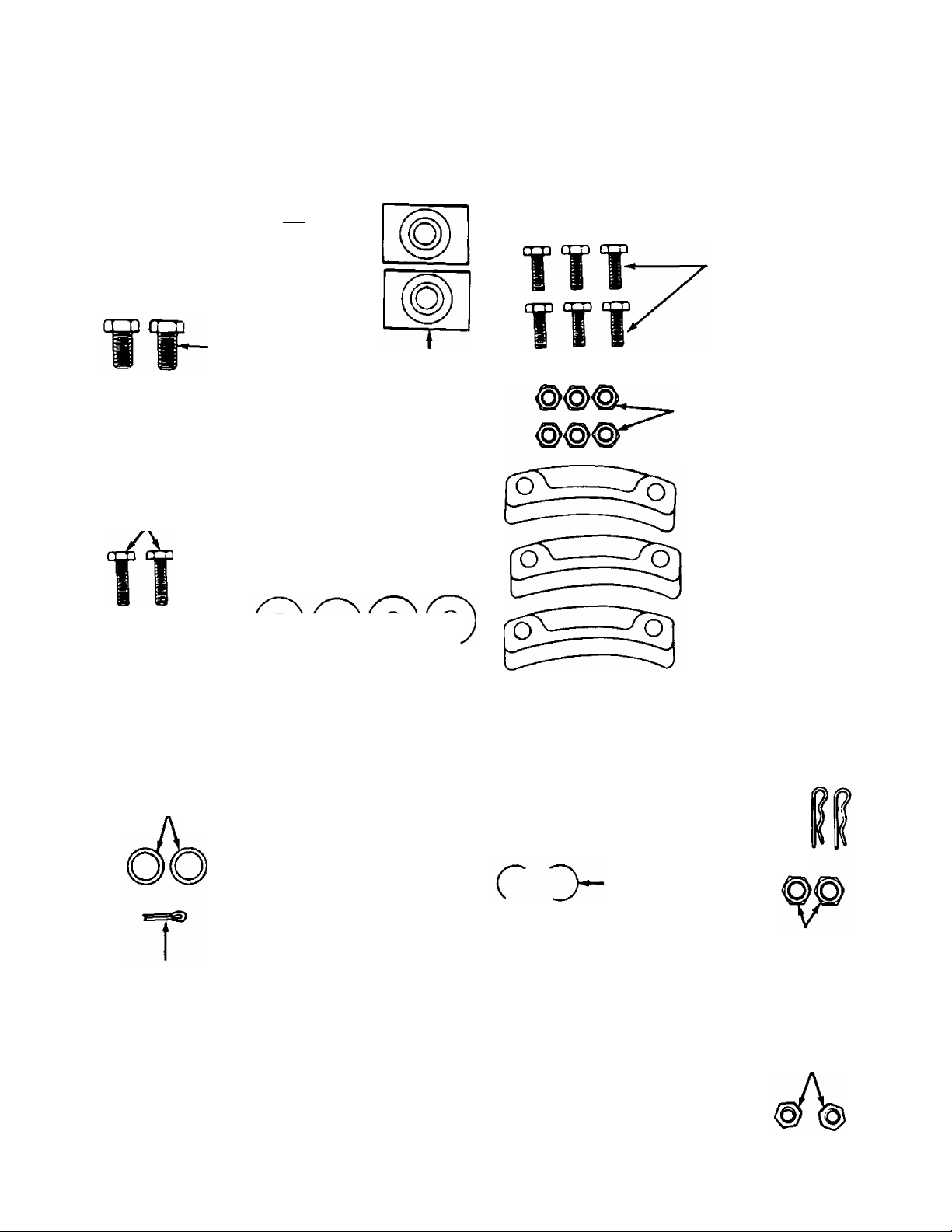
CONTENTS OF HARDWARE PACK
Lay out the hardware according to the illustration for identification purposes. Parts are illustrated approximately
one-half size. Part numbers are shown in parentheses.
{Hardware pack may contain extra items which are not used on your unit.)
ATTACHING THE HANDLE ASSEMBLY
Hex Bolts rrnrnTI
5/16-18 X1-3/4" ^
Long (710-3180)
^^L-1/4-20 Thread
(736-0287)
5/16-18x5/8"
Long (710-0538)
—Was hers
5/16" I.D.
(736-0119)
Hex Bolts*
1/4-20 X
7/8" Long
(710-0252)
Carriage
Bolts*“
5/16-18 X
1-1/2" Long
(710-1250)
--
Hex Bolts
Handle Tabs
(784-5599)
Lock
Cupped
Washers*
1/4" I.D—
(736-0270)
C“P^gWa8hers*-4 O ) ( O K O ) ( O
(£)
©
W
ATTACHING THE CHUTE ASSEMBLY
B
1/4-20 X 3/4" Long
Hex Lock Nuts
1/4-20 Thread
(712-3027)
Hex Bolts
(710-3015)
Chute Flange
Keepers
(731-0851)
(736-0242)
Hex Nuts*
5/16-18 Thread (712-0267)-».O
*May be preassembled on your unit.
ATTACHING THE CHUTE CRANK
Flat Washers
3/8" I.D. X 5/8" O.D.
(736-0140)
Lock Washer
Cotter Pin
(714-0507)
AUGER SHEAR BOLTS
The augers are secured to the spiral shaft with two hex bolts and hex
insert lock nuts. If you hit a foreign object or ice jam, the snow thrower is
designed so that the hex bolts wilt shear. Two replacement hex bolts and
nuts are provided for your convenience. Store in a safe place until needed.
5/16-18 Thread
(712-0267)
Hex Bolt
5/16-18x1-1/2"
Long —•
(710-0442)
5/16" I.D.
(736-0119)
Hex Nut
too
----
ATTACHING THE SHIFT ROD
AND CLUTCH CABLES
[o]3u-(
9)(o
(§h~
CgDCÿ
Ferrule
711-0677)
Flat Washers
5/16" I.D. X 5/8" O.D.
(736-0264)
Spring Washer
5/16" I.D.
(736-0271)
5/16-18x1-1/2'
Hairpin Clips
(714-0104)
Hex Bolts
Long
(710-0890)
Hex Nuts
(Come with
Clutch Cables)
Hex Lock Nuts
5/16-18 Thread
(712-0158)
Page 4
ASSEMBLY INSTRUCTIONS
IMPORTANT: This unit is shipped WITHOUT
GASOLINE or OIL. After assembly, see separate
engine manual for proper fuel and engine oil rec
ommendations.
NOTE: Reference to right or left side of the snow
thrower is from behind the unit In the operating
position.
Toois Required for Assembly:
(2) 1/2" Wrenches*
(2) 7/16" Wrenches*
(1) Pair of Pliers
*or Adjustable Wrenches
UNPACKING
1. Remove staples or break glue on the top flaps of
the carton. Remove any loose parts included with
unit (i.e., owner’s manual, etc.).
2. Cut along dotted lines and lay end of carton down
flat. Remove packing material.
3. Roll unit out of carton. Check carton thoroughly
for loose parts.
Loose Parts in Carton:
(1) Right Handle
(1) Left Handle
(1) Handle Panel Assembly and Chute Assembly
(Attached by Cable)
(1) Chute Crank Assembly
(1) Shift Rod
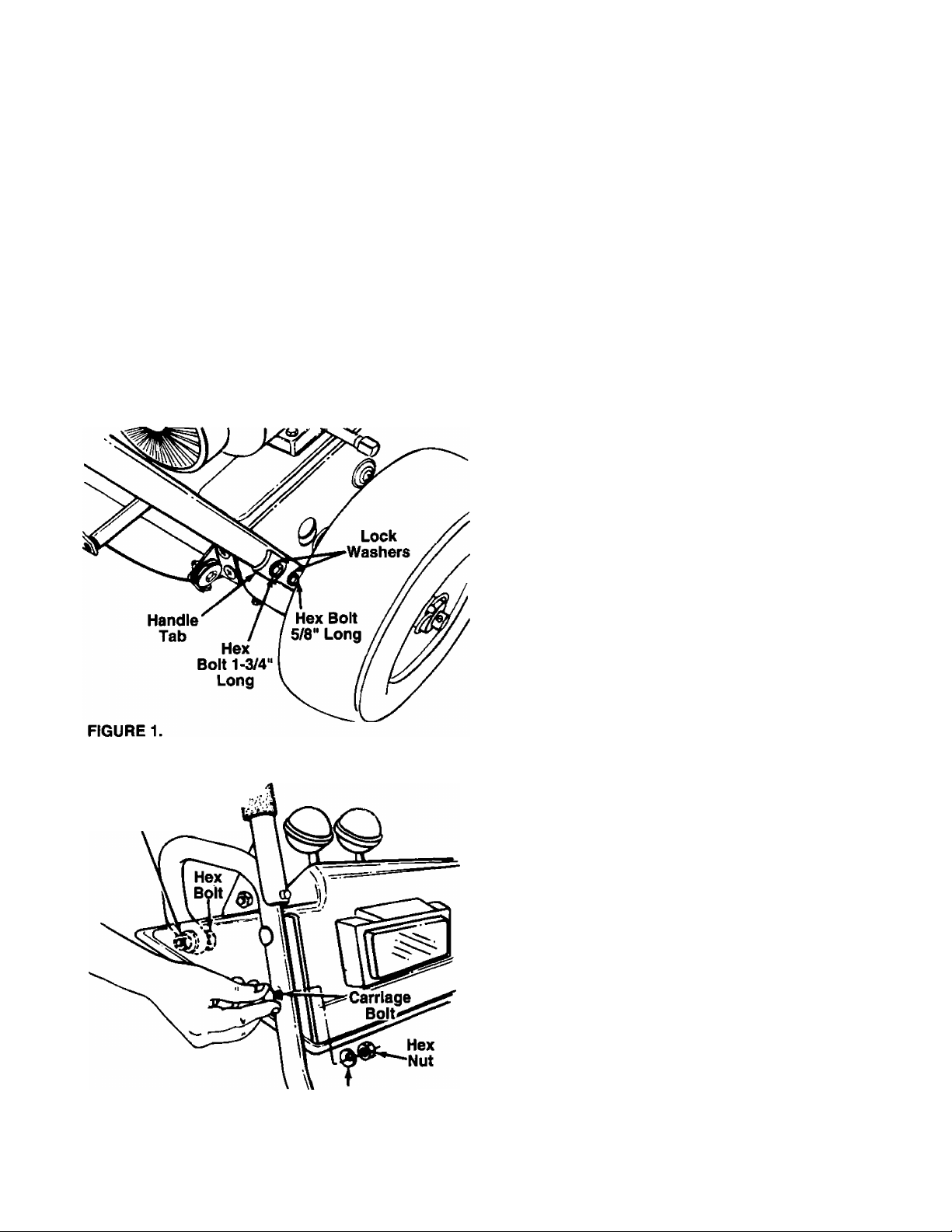
AHACHING THE HANDLE ASSEMBLY (Hardware A)
1. Place right handle in position against the snow
thrower so the flat side of the handle Is against
the snow thrower. Secure bottom hole in handle
to snow thrower using hex bolt 5/8" long and lock
------washer. See figure 1. Do not tighten at this time.
2. Place handle tab over the upper hole in handle so
the curve in the handle tab matches the curve in
the handle. Secure to the snow thrower using hex
bolt 1-3/4" long and lock washer. Do not tighten
at this time.
3. Attach the left handle in the same manner. Do not
tighten at this time.
NOTE: If the handle panel is already assembled to
the handles, skip steps 4, 5 and 6. Go to step 7.
Cupped Washer
Hex Nut
Cupped Washer
FIGURE 2.—Model 646F Shown
4. Place handle panel in position between the han
dles so the ends of the handle go through the
slots in the handle panel. See figure 2.
5. Secure front of handle panel with four carriage
bolts, cupped washers (cupped side against the
— handle panel) and hex nuts as shown in figure 2.
6. Secure rear of handle panel with two hex bolts,
cupped washers (cupped side against the handle)
and hex nuts.
7. Tighten the four hex bolts used to attach the bot
tom of the handles to the snow thrower frame.
Page 5
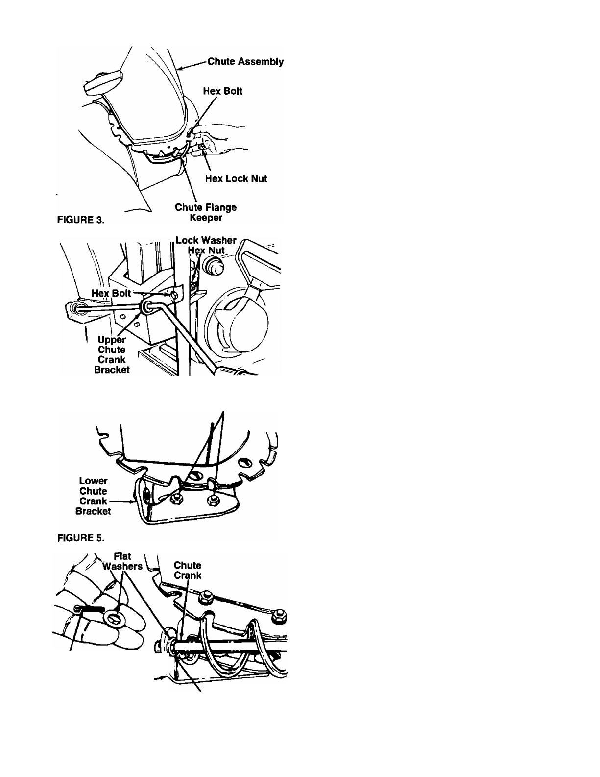
AHACHING THE CHUTE ASSEMBLY (Hardware B)
1. Grease the chute opening using a multi-purpose
automotive grease or equivalent.
2. Place chute assembly over chute opening, with
the opening in the chute assembly facing the front
of the unit. Place chute flange keepers beneath
lip of chute assembly. Insert hex bolt up through
chute flange keeper and chute assembly as
-----
shown in figure 3. Secure with hex lock nut. After
assembling all three chute flange keepers, tighten
all nuts and bolts securely, then back off 1/4 turn
to allow easier movement.
AHACHING THE CHUTE CRANK (Hardware C)
1. Insert hex bolt through the upper chute crank
-----
bracket. See figure 4.
2. Place the hex bolt into the hole provided in the
left handle. Secure with lock washer and hex nut.
Do not tighten until after attaching the other end
of the chute crank.
FIGURE 4.
Cotter nr
Pin , W
FIGURE 6.
Lower V'
Chute Crank
Bracket
Carriage Bolts
Hex Lock Nuts
Plastic
Bushing
3. Loosen the carriage bolts and hex lock nuts
which secure the lower chute crank bracket to the
------
extension on the left side of the chute assembly.
See figure 5.
4. Place one flat washer on the end of the chute
crank, then insert the end of the crank into the
hole in the plastic bushing in the chute crank
— bracket. See figure 6. Place the other flat washer
on the end of the chute crank, and insert cotter
pin into hole in the end of crank. Secure by bend
ing the ends of cotter pin in opposite directions.
5. Adjust the chute bracket so that the spiral on the
chute crank fully engages the teeth on the chute
assembly. Tighten the nuts on the lower chute
crank bracket securely. Tighten the hex bolt and
nut on the upper chute crank bracket on the han
dle.
Page 6
Cable
Guide
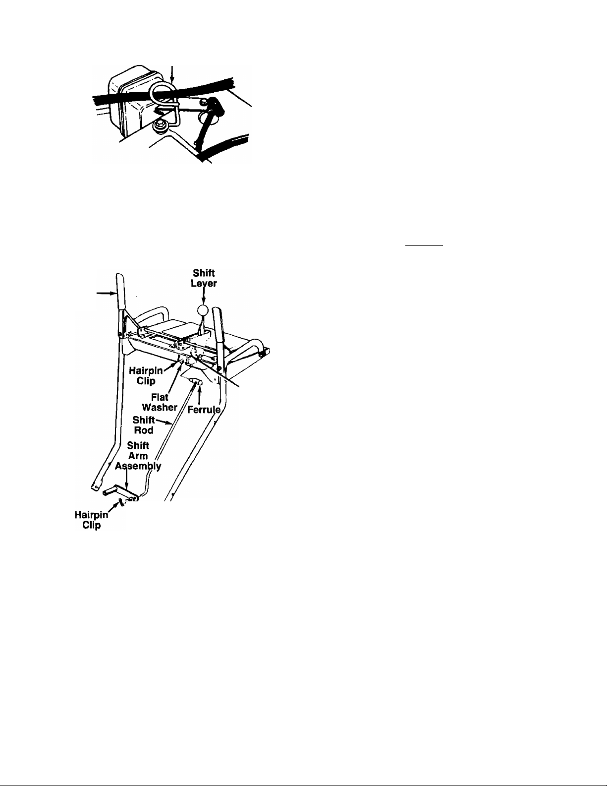
6. Models 646F and 666H only: Slip the cables
that run from the handle panel to the chute into
— the cable guide located on top of the engine. See
figure 7.
FIGURE 7.
IMPORTANT: Attach the shift rod and clutch cables as follows. THEN CHECK THE ADJUSTMENTS AS
INSTRUCTED, AND MAKE ANY FINAL ADJUSTMENTS NECESSARY BEFORE OPERATING YOUR
SNOW THROWER. Failure to follow the Instructions may cause damage to the snow thrower.
Traction
Drive
Clutch
FIGURE 8.
Spring
\ ^^^Washer
Fiat Washer
Bottom
Hole
AHACHING THE SHIFT ROD (Hardware D)
1. Insert the ferrule through the lower hole in the
shift lever (beneath the handle panel) from the left
side. Secure with flat washer and hairpin clip. See
------
figure 8.
2. Place the shift lever in the sixth (6) speed position
{all the way forward).
3. Start threading the shift rod into the ferrule. Push
down on the shift arm assembly as far as it will
go. Thread shift rod into the ferrule until the end
of the shift rod lines up with the hole in the shift
arm assembly. Secure with spring washer, flat
washer and hairpin clip.
Make certain to check for correct adjustment of the
shift rod as instructed in the Final Adjustment section
before operating the snow thrower.
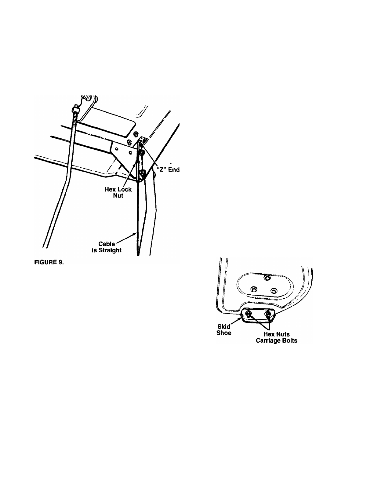
AHACHING THE CLUTCH CABLES
The “Z” end of the clutch cables are hooked into the
clutch grips on each handle. Attach cables as follows.
1. Thread the hex lock nuts (in hardware pack) all
the way up the threaded portion of the “Z’ ends
of the clutch cables.
2. Make certain each cable is in groove of cable
roller guides. Place the clutch grip in the raised
(up) position.
3. Thread the cable onto the threaded portion of the
“Z end until there is no slack in the cable, but the
cable is NOT tight. Do not overtighten cable.
See figure 9.
Page 7
WARNING: If cable is tightened so there
is tension on the cable with the clutch
A
4. When correct adjustment is reached, tighten the
grip released, the safety features of the
snow thrower may be overridden.
hex nut against the bottom portion of the cable to
lock it in position.
Now release the traction drive clutch grip, and spin
the wheels again. Move the shift lever back to the fast
reverse position, then all the way forward again.
There should be no resistance in the shift lever, and
the wheels should keep turning.
If you have resistance when moving the shift lever or
the wheels stop when they should not, loosen the lock
nut on the traction drive cable and unthread the cable
one turn. If the wheels do not stop when you engage
the traction drive clutch grip, loosen the lock nut on
the traction drive cable and thread the cable in one
turn. Recheck the adjustment and repeat adjustment
as necessary. Tighten the lock nut to secure the cable
when correct adjustment is reached.
NOTE: If you are uncertain that you have reached the
correct adjustment, refer to the Adjustment section on
page 10.
ADJUSTING THE SKID SHOES
The space between the shave plate and the ground
can be adjusted. For close snow removal, place skid
shoes in the low position. Use middle or high position
when area to be cleared is uneven. See figure 10.
Adjust skid shoes by loosening the four hex nuts and
carriage bolts and moving skid shoes to desired posi
tion. Make certain the entire bottom surface of skid
shoe is against the ground to avoid uneven wear on
the skid shoes. Retighten nuts and bolts securely.
FINAL ADJUSTMENTS
Auger Drive Clutch
To check the adjustment of the auger drive clutch,
push forward on the left hand clutch grip (depress the
rubber bumper). There should be slack in the cable.
Release the clutch grip. The cable should be straight.
Make certain you can depress the auger drive clutch
grip against the left handle completely.
If necessary, loosen the hex lock nut and thread the
cable in (for less slack) or out (for more slack) as nec
essary. Refer to figure 9. Recheck the adjustment.
Tighten the lock nut against the cable when correct
adjustment is reached.
Traction Drive Clutch and Shift Lever Adjustment
To check the adjustment of the traction drive clutch
and shift lever, tip the snow thrower fonvard so that it
rests on the auger housing. First move the shift lever
alt the way fonvard to sixth (6) position. With the trac
tion drive lever released, spin the snow thrower
wheels by hand. They should turn freely. Then
engage the traction drive clutch grip. The wheels
should stop turning.
FIGURE 10.
OPTIONAL ELECTRIC STARTER
If your unit is equipped with an optional electric starter
which has not been installed at the factory, install at
this time. Follow the instructions packed with the elec
tric starter for installation.
TIRE PRESSURE (Pneumatic Tires)
The tires are over-inflated for shipping purposes.
Check tire pressure and reduce to 15 to 20 psi.
NOTE: If the tire pressure is not equal in both tires,
the unit may pull to one side or the other.
Page 8
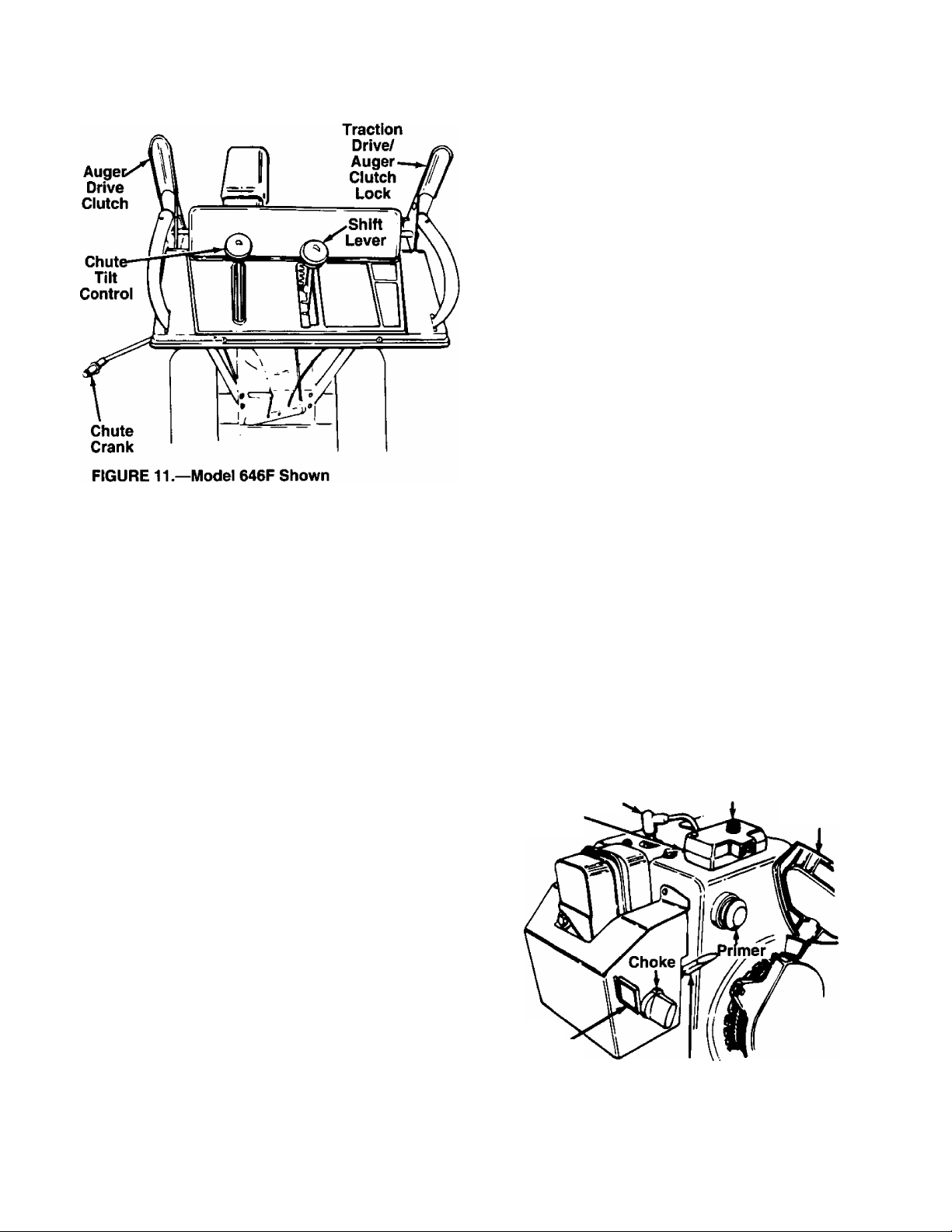
CONTROLS
SHIFT LEVER
(See figures 11 and 12)
The shift lever is located in the center
of the handle panel. The shift lever may
be moved into one of eight positions.
Run engine with throttle in the fast posi
tion. Use the shift lever to determine
ground speed.
Forward—one of six speeds. Position
number one (1) is the slowest. Position
number six (6) is the fastest.
Reverse—two reverse (R) speeds. “R”
closest to the operator (all the way
back) is the faster of the two.
AUGER DRIVE (See figure 11)
The auger drive clutch is located on the left handle.
Squeeze the clutch grip to engage the augers.
Release to stop the snow throwing action. (Traction
drive clutch must also be released.)
FIGURE 12.
CHUTE CRANK (See figure 11)
The chute crank is located on left hand side of the
snow thrower.
To change the direction in which snow is thrown, turn
chute crank as follows:
1. Crank clockwise to discharge to the left.
2. Crank counterclockwise to discharge to the right.
CHUTE TILT CONTROL (See figure 11)
Models 646F and 666H only: The distance snow is
thrown can be adjusted by adjusting the angle of the
chute assembly. Move the chute tilt control fonvard to
decrease the distance, toward the rear to increase.
Model 616E only: To adjust chute assembly, loosen
the hand knob. Pivot the top of the chute assembly to
position desired. Retighten the hand knob. The sharp
er the angle, the shorter the distance snow is thrown.
THROTTLE CONTROL (See figure 13)
The throttle control is located on the engine. It regu
lates the speed of the engine.
SAFETY IGNITION SWITCH (See figure 13)
The ignition key must be inserted in the switch before
the unit will start. Remove the ignition key when snow
thrower is not in use.
Starter
Button
Rope Starter
Handle
Switch
Box
Spark
Plug
TRACTION DRIVE/AUGER CLUTCH LOCK
(See figure 11)
The traction drive clutch is located on the right handle.
Squeeze the traction drive clutch to engage the wheel
drive. Release to stop.
This same lever also locks the auger clutch so you
can turn the chute crank without interrupting the snow
throwing process. If the auger drive clutch is engaged
with the traction drive clutch engaged, the operator
can release the auger drive clutch (on the left handle)
and the augers will remain engaged. Release the
traction drive clutch to stop both the augers and wheel
drive (auger drive clutch must also be released).
Ignition
Key
FIGURE 13.—Model 646F Shown
Throttle
Control
Page 9

OPERATION
GAS AND OIL FILL-UP
Service the engine with gasoline and oil as
instructed in the separate engine manual packed with
your snow thrower. Read instructions carefully.
NOTE: Your snow thrower is shipped without oii; how
ever, a small amount of oil may be present from the
factory. Do not overfill.
WARNING: Never fill fuel tank indoors,
A
with engine running or while engine is
hot. Do not smoke when filling fuel tank.
ELECTRIC STARTER (Optional)
WARNING: The optional electric starter is equipped
with a three-wire power cord and plug, and is
designed to operate on 120 volt AC household cur
rent. It must be properly grounded at all times to avoid
the possibility of electric shock which may be injurious
to the operator. Follow all instructions carefully.
Determine that your house wiring is a three-wire
grounded system. Ask a licensed electrician if you are
not certain. If your house wiring system is not a threewire grounded system, do not use this electric starter
under any conditions. If your system is grounded and
a three-hole receptacle is not available at the point
your starter will normally be used, one should be
installed by a licensed electrician.
When connecting the power cord, always connect
cord to starter on engine first, then plug the other end
into a three-hole grounded receptacle.
When disconnecting the power cord, always unplug
the end from the three-hole grounded receptacle first.
4. Rotate choke knob to FULL choke position (cold
engine start).
If engine is warm, place choke in OFF position
instead of FULL.
Electric Start Only (Optional): Connect power
5.
cord to switch box on engine. Plug the other end
of power cord into a three-hole, grounded 120
volt AC receptacle.
Push primer button two or three times. See figure
6.
13.
If engine is warm, push primer button once only.
NOTE: Always cover vent hole in primer button when
pushing. Additional priming may be necessary for first
start if temperature is below 15°F.
7. Recoil Start: Grasp starter handle (see figure 13)
and pull rope out slowly, until it pulls slightly hard
er. Let rope rewind slowly. Pull starter handle
rapidly. Do not allow handle to snap back. Allow it
to rewind slowly while keeping a firm hold on the
starter handle.
Electric Start (Optional): Push starter button on
top of the engine to crank the engine. When
engine starts, release starter button.
8.
Repeat step 7 until engine starts. If engine fails to
start, repeat steps 6 and 7 until engine starts.
9.
As engine warms up and begins to operate even
ly, rotate choke knob slowly to OFF position. If
engine falters, return to FULL choke, then slowly
move to OFF position.
A DANGER
TO START ENGINE
IMPORTANT: If unit shows any sign of motion (drive
or augers) with the clutch grips disengaged, shut
engine off immediately. Readjust as instructed in the
“Final Adjustments” section of the Assembly
Instructions.
NOTE: Models 646F and 666H only: Your snow
thrower is equipped with a headlight. The headlight
will be on when the engine is running.
1. Attach spark plug wire to spark plug.
2. Make certain the auger drive and traction
drive ciutch grips are in the disengaged
(released) position.
3. Move throttle control up to FAST position. Insert
ignition key into slot. See figure 13. Be certain it
snaps into place. Do not turn key.
AVOID INJURY FROM ROTATING
AUGER — KEEP HANDS, FEET
AND CLOTHING AWAY.
TO STOP ENGINE
1. Run engine for a few minutes before stopping to
help dry off any moisture on the engine.
2. To help prevent possible freeze-up of starter, pro
ceed as follows.
Page 10

Optional Electric Starter: Connect power cord to
switch box on engine, then to 120 volt AC receptacle.
With the engine running, push starter button and spin
the starter for several seconds. The unusual sound
made by spinning the starter will not harm engine or
starter. Disconnect the power cord from receptacle
first, and then from switch box.
Recoil Starter: With engine running, pull starter rope
with a rapid, continuous full arm stroke three or four
times. Pulling the starter rope will produce a loud clat
tering sound, which is not harmful to the engine or
starter.
3. To stop engine, remove the ignition key. Do not
turn key. Disconnect the spark plug wire from the
spark plug to prevent accidental starting while
equipment is unattended.
NOTE: Do not lose ignition key. Keep it in a safe
piace. Engine wiii not start without the ignition key.
4. Wipe all snow and moisture from the carburetor
cover in the area of the control levers. Also, move
control levers back and forth several times. Leave
throttle control lever in the STOP or OFF position.
Leave choke control in the FULL choke position.
WARNING: Temperature of muffler and
surrounding areas may exceed 150°F.
A
1. For most efficient snow removal, remove snow
2. Discharge snow downwind whenever possible.
3. Set the skid shoes 1/4" below the scraper bar for
4. Be certain to follow the precautions listed under
5. Clean the snow thrower thoroughly after each
Avoid these areas.
immediately after it falls.
Slightly overlap each previous swath.
normal usage. The skid shoes may be adjusted
upward for hard-packed snow. Adjust downward
when using on gravel or crushed rock.
“To Stop Engine” on page 9 to prevent possible
freeze-up.
use.
ADJUSTMENTS
WARNING: NEVER attempt to clean
chute or make any adjustments while
A
engine is running.
A
DANGER
SHUT OFF ENGINE
BEFORE UNCLOG
GING DISCHARGE
CHUTE.
TO ENGAGE DRIVE
1. With the engine running near top speed, move
shift lever into one of the six FORWARD positions
or two REVERSE positions. Select a speed
appropriate for the snow conditions that exist.
Use the slower speeds until you are familiar with
the operation of the snow thrower.
2. Squeeze the traction drive clutch grip against the
right handle and the snow thrower will move.
Release it and the drive motion will stop.
NOTE: NEVER move shift lever without first releasing
the drive clutch.
TIRE CHAINS (Optional Equipment)
Tire chains should be used whenever extra traction is
needed.
OPERATING TIPS
NOTE: Allow the engine to warm up for a few minutes
as the engine wiii not develop full power until it reach
es operating temperature.
CHUTE ASSEMBLY ADJUSTMENT
The distance snow is thrown can be adjusted by
adjusting the angle of the chute assembly. Refer to
the Control section of this manual.
SKID SHOE ADJUSTMENT
The space between the shave plate and the ground
can be adjusted. Refer to page 7 of the Assembly
Instructions.
TRACTION DRIVE CLUTCH ADJUSTMENT
Refer to the Final Adjustment section of the Assembly
Instructions to adjust the traction drive clutch. If you
are uncertain that you have reached the correct
adjustment, the adjustment can be physically checked
as follows.
With the snow thrower tipped fonward (be certain to
drain the gasoline or place plastic film under the gas
cap if the snow thrower has already been operated),
remove the frame cover underneath the snow thrower
by removing six self-tapping screws.
With the traction drive clutch released, there must be
clearance between the friction wheel and the drive
plate in all positions of the shift lever. With the traction
drive clutched engaged, the friction wheel must con
tact the drive plate. See figure 14.
If adjustment is necessary, loosen the lock nut on the
traction drive cable and thread the cable in or out as
necessary. Tighten the lock nut to secure the cable
when correct adjustment is reached. Reassemble the
frame cover.
NOTE: If you placed plastic under the gas cap, be
certain to remove it.
10
Page 11

Drive
Plate
FIGURE 14.
AUGER CLUTCH ADJUSTMENT
To adjust the auger clutch, refer to Final Adjustment
section of Assembly Instructions.
SHIFT ROD ADJUSTMENT
To adjust the shift rod, remove the hairpin clip and flat
washer which secure the shift rod to the shift arm
assembly. Refer to figure 8. Adjust as specified in
Assembly Instructions.
FIGUREIS.
WARNING: Disconnect the spark plug
wire and ground against the engine
A
before performing any repairs or mainte
nance.
Outside Hole
in Axle
MAINTENANCE
CARBURETOR ADJUSTMENT
WARNING: If any adjustments are made
to the engine while the engine Is running
A
Minor carburetor adjustment may be required to com
pensate for differences in fuel, temperature, altitude
and load.
Refer to the separate engine manual packed with
your unit for carburetor adjustment information.
DRIVE WHEELS
The wheels may be adjusted for two different meth
ods of operation. The adjustment is made by placing
the klick pins in one of two different holes on the right
side of the unit. See figure 15.
1. One Wheel Driving—Place klick pin in the out
2. Both Wheels Driving—Place klick pin in the hole
(e.g. carburetor), keep clear of all moving
parts. Be careful of heated surfaces and
muffler.
side axle hole on the right side. This position
gives power drive to the left wheel only, making
the unit easier to maneuver.
in the hub next to the rim on the right side. This
position is good for heavy snow as there is power
drive in both wheels.
LUBRICATION
Gear Shaft
Lubricate the gear shaft with “Slick 50 Grease” at
least once a season or after every 25 hours of opera
tion (available at automotive stores, or order part
number 737-0290). Refer to figure 14.
IMPORTANT: Keep all grease and oil off of the
friction wheel and drive plate.
Shifting Mechanism
Lubricate the shifting mechanism and pivot points on
the shift rod with engine oil at least once a season or
after every 25 hours of operation.
Traction Drive/Auger Clutch Lock
The cams on the ends of the control rods which inter
lock the traction drive and auger drive clutches must
be lubricated at least once a season or every twentyfive hours of operation. The cams can be accessed
beneath the handle panel. Use a multi-purpose auto
motive grease.
Gear Case
The gear case is lubricated with grease at the factory
and does not require checking. If disassembled for
any reason, lubricate with 2 ounces of Shell Alvania
grease, part number 737-0168.
Bearings
Lubricate the auger and wheel bearings once a sea
son with light oil.
11
Page 12

AUGERS
The augers are secured to the spiral shaft with two
hex bolts and hex lock nuts. See figure 16. If you hit a
foreign object or ice jam, the snow thrower is
designed so that the hex bolts will shear.
If the augers will not turn, check to see if the hex bolts
have sheared. Two replacement hex bolts and hex
lock nuts have been provided with the snow thrower.
For future use, order part number 710-0890 (hex bolt
5/16-18 X 1.5" long) and 712-0158 (hex lock nut
SHAVE PLATE AND SKID SHDES
The shave plate and skid shoes on the bottom of the
snow thrower are subject to wear. They should be
checked periodically and replaced when necessary.
To remove skid shoes, remove the four carriage bolts,
belleville washers and hex nuts which attach them to
the snow thrower. Reassemble new skid shoes with
the four carriage bolts, belleville washers (cupped
side goes against skid shoes) and hex nuts. Make
certain the skid shoes are adjusted to be level.
To remove shave plate, remove the carriage bolts,
belleville washers and hex nuts which attach it to the
snow thrower housing. Reassemble new shave plate,
making sure heads of the carriage bolts are to the
inside of the housing. Tighten securely.
Self-Tapping
Cover
FIGURE 17.
2. Drain the gasoline from the snow thrower, or
place a piece of plastic under the gas cap.
3. Tip the snow thrower up and forward so that it
rests on the housing.
4. Remove six self-tapping screws from the frame
cover underneath the snow thrower.
5. Roll the front and rear auger belts off the engine
pulley. See figure 18.
Screws
ENGINE
Refer to separate engine manual for all engine
maintenance procedures.
BELT REMOVAL AND REPLACEMENT
WARNING: Disconnect the spark plug
wire from the spark plug and ground.
A
AUGER BELTS
NOTE: It is necessary to remove both belts in order to
change either one. If changing just one belt, be cer
tain to check the condition of the other belt (model
616E has only one auger belt).
1. Remove the plastic belt cover on the front of the
engine by removing the two self-tapping screws.
See figure 17.
FIGURE 18.
6. Unhook the idler spring from the hex bolt on the
auger housing. See figure 19.
7. Unhook the support bracket spring from the
frame.
8. Lift the front auger belt from the auger pulley, and
slip belt between the support bracket and the
auger pulley. See figure 19. Repeat this step for
rear auger belt (except Model 616E).
9. Replace both auger drive belts by following
instructions in reverse order.
12
Page 13

Support
Bracket
Rear
Auger
Belt
Front
Auger
Belt
Idler
FIGURE 19.
DRIVE BELT
1. Follow steps 1 through 4 of previous instructions.
2. Pull idler pulley up, and lift belt off engine pulley
and friction wheel disc. See figure 18.
3. Using a 7/16" wrench, loosen the nut on the stop
bolt until the support bracket rests on the auger
pulley. See figure 20.
4. Slip belt between friction wheel and friction wheel
disc. See figure 20. Remove and replace belt.
Reassemble following the instructions in reverse
order.
NOTE: The support bracket must rest on the stop bolt
after the new belt has been assembled. See figure 20.
Spring
Auger Support
Housing Bracket
Spring
Frame
CHANGING THE FRICTION WHEEL RUBBER
The rubber on the friction wheel is subject to wear
and should be checked after 25 hours of operation,
and periodically thereafter. Replace the friction wheel
rubber if any signs of wear or cracking are found.
1. Drain the gasoline from the snow thrower, or
place a piece of plastic under the gas cap.
2. Tip the snow thrower up and forward, so that it
rests on the housing.
3. Remove six self-tapping screws from the frame
cover underneath the snow thrower.
4. Remove the klick pins which secure the wheels,
and remove the wheels from the axle.
5. Remove the gear shaft from the unit by removing
the bolts, lock washers and flat washers from
each side of the frame. See figure 21. Hold the
friction wheel assembly, and slide the gear shaft
out of the unit toward the right hand side. Refer to
figure 14.
6. Remove the six screws from the friction wheel
assembly (three from each side). Remove the
friction wheel rubber from between the friction
wheel plate.
7. Reassemble new friction wheel rubber to the fric
tion wheel assembly, tightening the six screws in
rotation and with equal force.
8. Slide the friction wheel assembly up onto the shift
mechanism as shown in figure 14, and slide the
gear shaft back into the unit. Reassemble in
reverse order.
Page 14

OFF-SEASON STORAGE
WARNING: Never store engine with fuel
in tank indoors or in poorly ventilated
A
If unit is to be stored over 30 days, prepare for stor
age as follows:
1. Remove all gasoline from carburetor and fuel
A
areas, where fuel fumes may reach an
open flame, spark or pilot light as on a
furnace, water heater, clothes dryer or
other gas appliance.
tank to prevent gum deposits from forming on
these parts and causing possible malfunction of
engine.
a. Run engine until fuel tank is empty and engine
stops due to lack of fuel.
b. Drain carburetor by pressing upward on bowl
drain, located below the carburetor cover.
WARNING: Drain fuel into approved con
tainer outdoors, away from open flame.
Be certain engine Is cool. Do not smoke.
Fuel left in engine during warm weather
deteriorates and will cause serious start
ing problems.
NOTE: Fuel stabilizer (such as STA~BIL) is an accept
able alternative in minimizing the formation of fuel
gum deposits during storage. Add stabilizer to gaso
line in fuel tank or storage container. Always follow
mix ratio found on stabilizer container. Run engine at
least 10 minutes after adding stabilizer to allow it to
reach carburetor. Do not drain carburetor if using fuel
stabilizer.
2. Remove spark plug and pour one (1) ounce of
engine oil through spark plug hole into cylinder.
Crank engine several times to distribute oil.
Replace spark plug.
3. Remove all dirt from exterior of engine and equip
ment.
4. Follow lubrication recommendations on page 11.
NOTE; When storing any type of power equipment in
an unventilated or metal storage shed, care should be
taken to rust proof the equipment. Using a light oil or
silicone, coat the equipment, especially any chains,
springs, bearings and cables.
14
Page 15

TROUBLE SHOOTING GUIDE
Trouble
Engine fails to start
Engine runs erratic
Loss of power
Engine overheats 1. Engine oil level low.
Excessive vibration
Possible Cause(s)
1. Fuel tank empty, or stale fuel.
2. Blocked fuel line.
3. Key not in switch on engine.
4. Spark plug wire disconnected.
5. Faulty spark plug.
1. Unit running on CHOKE.
2. Blocked fuel line or stale fuel.
3. Water or dirt in fuel system.
4. Carburetor out of adjustment.
1. Spark plug wire loose.
2. Gas cap vent hole plugged.
2. Carburetor not adjusted properly.
Loose parts or damaged impeller. Stop engine immediately and
Corrective Action
1. Fill tank with clean, fresh gasoline.
2. Clean fuel line.
3. Insert key.
4. Connect wire to spark plug.
5. Clean, adjust gap or replace.
1. Turn choke knob to OFF position.
2. Clean fuel line; fill tank with clean
fresh gasoline.
3. Use carburetor bowl drain to drain
fuel tank. Refill with fresh fuel.
4. Adjust carburetor. See separate
engine manual.
1. Connect and tighten spark plug
wire.
2. Remove ice and snow from cap.
Be certain vent hole is clear.
1. Fill crankcase with proper oil.
2. Adjust carburetor. See separate
engine manual.
disconnect spark plug wire. Tighten
all bolts and nuts. Make all
necessary repairs. If vibration
continues, have unit serviced by
authorized service dealer.
Hard to shift, or will
not shift
Unit fails to propel itself
Unit fails to discharge
snow
NOTE; For repairs beyond the minor adjustments listed above, please contact your nearest authorized sen/ice dealer.
Shift rod misadjusted.
1. Incorrect adjustment of drive clutch.
2. Drive belt loose or damaged.
1. Auger shear bolt broken.
2. Discharge chute clogged.
3. Foreign object lodged in auger.
4. Incorrect adjustment of auger drive
clutch.
5. Auger drive belt loose or damaged.
Readjust shift rod. See Adjustment
section of this manual.
1. Adjust drive clutch. Refer to
Adjustment section.
2. Replace drive belt. Refer to
Maintenance section.
1. Replace auger shear bolt. Refer to
Maintenance section.
2. Stop engine immediately and
disconnect spark plug wire. Clean
discharge chute and inside of auger
housing.
3. Stop engine immediately and
disconnect spark plug wire.
Remove object from auger.
4. Adjust auger clutch. Refer to
Adjustment section.
5. Replace auger drive belt. Refer to
Maintenance section.
15
Page 16

Models 616E, 646F and 666H
<í
АО
16
Page 17

Models 616E, 646F and 666H
PARTS LIST FOR MODELS 616E, 646F AND 666H SNOW THROWERS
REF.
NO.
10
11
13
14
15
16
17
18
19
20 684-0032A
21
22
23
24
25
26 714-0111
27
28
29
30
31
32
1
725-1646
2
3
710-0776A
4
736-0242
5
6
714-0507
7
736-0509
8
9
784-5682
732-0145
749-0908
749-0909
684-0036
684-0037
PART
NO.
710-0351
748-0362
784-5681
726-0321
712-0271
CODE
DESCRIPTION
Lamp Housing w/Lensf
Truss Mach. B-Tap Scr. #10 x .5
Hex AB-Tap Scr. 1/4 x .62" Lg.f
Bell-Wash. .325" I.D. x .88" O.D.
Cam Handle Lock 37
Cotter Pin 3/32" Dia. x .75" Lg.
Washer (Special) .72" O.D.
Handle Support Brkt.—L.H.
Handle Support Brkt.—R.H.
Compression Spring
Retaining Clipf
Handle—R.H.
Handle—L.H.
Hex Sems Nut 1/4-20 Thd.t 45
Engagement Handle—R.H.
Engagement Handle—L.H.
748-0363 Pawl Handle Lock 47
747-0877
Rod Cam
Handle Panel Supportf
684-0033A Handle Panel Support (616E—
Not Shown)
710-0599
Hex Wash. Hd. TT-Tap Scr.
1/4-20 X .5" Lg. 52
711-0946
712-0116
712-0267
712-0287
Clevis Pin .437" Dia. x .65" Lg.
Hex Ins. L-Nut 3/8-24 Thd.
Hex Nut 5/16-18 Thd."
Hex Nut 1/4-20 Thd."
Cotter Pin 3/32" Dia. x 1" Lg.
732-0193
735-0199A
736-0105
736-0119
736-0175
746-0897
Compression Spring
Rubber Bumper
Bell-Wash. .38" I.D. x .88" O.D.
L-Wash. 5/16" I.D.*
Spring Wash. .265" I.D.
Auger Clutch Cable
REF.
NO.
33
34
35 720-0232 Shift Knob
36
38
40
41
42
43
44
46
48
49
50
51
53
57
58
59
60
61
62
63
64
65
PART
NO.
CODE
DESCRIPTION
746-0898 Drive Clutch Cable
747-0798
784-0297
Shift Rod
Shift Handle
784-5679 Handle Brkt.—L.H.
784-5680
736-0264
Handle Brkt.—R.H.
FI-Wash. .344" I.D. x .62" O.D.
714-0104 Internal Cotter Pin 5/16" Dia.
711-0677
710-0538
Ferrule
Hex Bolt 5/16-18 X .62" Lg.
(Special)
710-3180
Hex Bolt 5/16-18 X 1.75" Lg.
(Gr. 5)
784-5599
710-1250
Handle Tab
Curved Carr. Bolt 5/16-18 x 1.5"
Lg.
731-1334
731-1347
731-1313
746-0896
746-0901
736-0425
784-5604
Handle Panel (616E-Not Shown)
Handle Panelt
Cable Guidef
Chute Control Cablet
Chute Control Cable w/Clipt
Belt-Wash. .325" I.D. x .93" O.D.f
Chute Tilt Handlet
712-0158 Hex Cent. L-Nut 5/16-18 Thd.t
712-0267
736-0271
712-0121
Hex Nut 5/16-18 Thd.
Spr. Wash. .32" I.D. x .62" O.D.
Hex Nut #10-24 Thd. (Incl.
w/Ref. 32 & 33)
725-0157
736-0506
710-0252
Cable Tiet
Washer (Special) 1.25" O.D.t
Hex Bolt 1/4-20 X .85" Lg.*
736-0270 Bell-Wash. .265" I.D. x .75" O.D.
725-1645
629-0059
Bulbt
Wire Harnesst
fModel 646F and 666H Only.
MODELS
616E (500)
646F (850) Instruction
666H (1050)
All Models
LABELS
TYPE
DESCRIPTION
Instruction Right Control Panel
Left Control Panel w/o Chute
Axle Pin Label
Decorative Snow Boss 500
Handle Panel w/o Lights
Handle Panel Center
Right Control Panel
Left Control Panel
Decorative
Snow Boss 850
Handle Panel with Lights
8 HP Snow Thrower Engine
Instruction
Handle Panel Center
Right Control Panel
Left Control Panel
Decorative
Snow Boss 1050
Handle Pane! with Lights
10 HP Snow Thrower Engine
Danger
Warning
Auger
Top of Chute
17
PART NO.
777-0932
777-0934
777-8160
777-2377
777-2393
777-0873
777-0932
777-0933
777-2379
777-2382
777-2436
777-0873
777-0932
777-0933
777-2381
777-2382
777-2438
777-0783
777-2361
777-8088B
Page 18

Models 616E, 646F and 666H
Al ЬЗ
18
Page 19

Models 616E, 646F and 666H
PARTS LIST FOR MODELS 616E, 646F AND 666H SNOW THROWERS
REF.
NO.
10
11
12
13
14
15
16
17
19
20
21 684-0039A 24" Auger Housing Ass’y. (616E)
22
23
24
25
26
27
28
29
30
31
32
33
34
35
36
37
38
40
41
42
43
44
45
46
PART
NO.
1
618-0120
618-0121
618-0122
2
719-0292
3
721-0179
4
741-0339
5
719-0293
6
737-3000
7
710-0642
8
711-0908 24" Auger Shaft (616E)
711-0909
711-1024
9
714-0388
715-0143
717-0526
717-0528
CODE
DESCRIPTION
Worm Drive Ass’y. Comp. {616E) 47
Worm Drive Ass’y. Comp. (646F)
Auger Gear Box Ass’y. (666H)
Reducer Housing—L.H.
Oil Seal
Flange Bearing .75" I.D.
Reducer Housing—R.H.
Grease Fitting
Hex TT-Tap Scr. 1/4-20 x .75" Lg.
26" Auger Shaft (646F)
N 30" Auger Shaft (666H)
#61 Hi-Pro Key 3/16" X 5/8" Dia.
Spiral Pin 1.25" Lg.
Impeller Shaft 64
Worm Gear
REF.
NO.
50
51
52
53
54
55
56
57
59
60
61
62
63
718-0186 Thrust Collar
721-0327
736-0351
Oil Seal
FI-Wash. .76" I.D. X 1.5" O.D.
736-0369 FI-Wash. .5" I.D. x1" O.D.
736-0445
741-0376
FI-Wash. .76"I.D. xl.49" O.D.
Flange Bearing .75" I.D.
748-0108 Flange Bearing .503" I.D.
65
684-0040A
684-0055
710-0157
26" Auger Housing Ass’y. (646F)
N 30" Auger Housing Ass’y. (666H)
Hex Bolt 5/16-24 X.75" Lg.*
67
68
69
710-0260 Carriage Bolt 5/16-18 x .62" Lg. 70 05845A
710-0451
Carriage Bolt 5/16-18 x .75" Lg.
712-0123 Hex Nut 5/16-24 Thd.*
712-0267
736-0119
Hex Nut 5/16-18 Thd.*
L-Wash.5/16"I.D.*
75
76
77
78
736-0242 Bell-Wash. .345" I.D. x .88" O.D. 79
784-5580 Slide Shoe
784-5581
24" Shave Plate (616E)
82
83 731-0921
784-5579 26" Shave Plate (646F)
784-5575
710-0286
N 30" Shave Plate (666H)
Truss Mach. Scr. 1/4-20 x .5" Lg.
84
85
712-0287 Hex Nut 1/4-20 Thd.* 86
731-1379
736-0175
710-0459
710-0812
712-0116
712-0181
712-0291
732-0611
736-0167 FI-Wash. 5/8" I.D. x 1.25"
736-0329
738-0281
756-0178
784-5632
Chute Adapter
Spring Washer 1/4" I.D.
Hex Bolt 3/8-24 x 1.5" Lg. (Gr. 5)
87
88
Hex Bolt 1/4-20 x .75" Lg. (Gr. 5)
Hex Ins. L-Nut 3/8-24 Thd.
89
Hex Top L-Nut 3/8-16 Thd. 90
Hex L-Nut 1/4-20 Thd.
91
Ext. Spring 3.6" Lg.
92
L-Wash. 1/4" I.D.*
Shid. Bolt .625" Dia. x .170" Lg.
Fl-ldler2.75" O.D.
Auger Idler Brkt.
95
96
97
PART
N0.
710-1087
741-0309
705-5187A
CODE
Hex Bolt 5/16-18 X 5/8“ Lg.
Ball Bearing .75" I.D.
Blower Fan Ass’y.
DESCRIPTION
715-0114 Spiral Pin 1.5" Lg.
710-0890
712-0158
736-0188
Shear Bolt 5/16-18 x 1.5" Lg.
Hex Cent. L-Nut 5/16-18 Thd.
FI-Wash. .76" I.D. xl.49"
741-0493A Flange Bushing .8" I.D.
684-0022
712-0429
714-0507
Chute Crank Ass’y.
Hex Ins. L-Nut 5/16-18 Thd.
Cotter Pin 3/32" Dia. x .75"
715-0138 Roll Pin 1/8" Dia. X.63" Lg.
720-0201A
726-0100
705-5189
Chute Crank Knob
Push Nut
Spiral Ass’y.—L.H. (616E)
705-5188 Spiral Ass’y.—R.H. (616E—
Not Shown)
705-5193
705-5192
Spiral Ass’y.—L.H. (646F)
Spiral Ass’y.—R.H. (646F—
Not Shown)
Spiral Ass’y.—L.H. (666H)
705-5249
705-5248
N
N Spiral Ass’y.—R.H. (666H—
Not Shown)
736-0140
784-5678
784-5647
FI-Wash. .385" I.D. x .62" O.D.
Upper Chute Crank Brkt.
Lower Chute Crank Brkt.
741-0475 Plastic Bushing .38" I.D.
Bearing Housing
741-0300
05931
Plastic Bearing w/Flats
Bearing Housing
731-0851 Chute Flange Keeper
720-0241
710-0262
712-0107
Knob (616E)
Carriage Bolt 5/16-18 x 1.5" Lg.
Hex L-Nut 1/4-20 Thd.
Upper Chute (616E)
731-1320 Upper Chute (646F & 666H)
731-1300A
736-0231
710-0255
736-0142
Lower Chute
N
FI-Wash. .344" I.D. x 1.125"
Truss Mach. Scr. 1/4-20 x .75"
Lg-
FI-Wash. 1/4" I.D.
710-0776A Hex AB-Tap Scr. 1/4 x .62" Lg.
(646F)
731-1313 Cable Guide (646F & 666H)
784-5594
746-0896
Cable Bracket (646F & 666H)
Chute Control Cable
(646F & 666H)
746-0901 Chute Control Cable w/Clip
(646F)
710-0442
705-5225
721-0325
Hex Bolt 5/16-18 X 1.5" Lg.
Chute Reinforcement
Plug
Tor faster service obtain standard nuts, bolts and washers locally.
If these items cannot be obtained locally, order by part number
and size as shown on parts list.
19
Page 20

Models 616E, 646F and 666H
20
Page 21

Models 616E, 646F and 666H
PARTS LIST FOR MODELS 616E, 646F AND 666H SNOW THROWERS
REF.
NO.
10
11
12
13
14
15
16
17
18
19
20
22
23
24 732-0339
25
26
27
28
1
2
PART
NO.
—
710-0599
CODE DESCRIPTION
Engine**
Hex Wash. Hd. TT-Tap Scr.
1/4-20X.5" Lg.
3
4
731-1324
714-0133
Belt Cover
Sq.-Key 3/16 X 1.5" Lg.
(646F & 666H)
714-0122
5
710-3166 Hex Patch Bolt 5/16-24 x 1" Lg.
Sq.-Key 3/16 X .75“ Lg. (616E)
(Gr. 5)
6
7
8
9
656-0009
710-0342
756-0313
732-0264
Friction Wheel Disc Ass’y*
Hex Bolt 3/8-16 X 1.25" Lg.
Fl-ldler2.12" O.D.
Ext. Spring 2.5" Lg.
712-0181 Hex Top L-Nut 3/8-16 Thd.
710-0230
Hex Bolt 1/4-28 x ,5" Lg. 42
736-0329 L-Wash. 1/4" I.D.*
684-0021 Friction Wheel Support Brkt.
Ass’y-
712-0711
736-0105
Hex Jam Nut 3/8-24 Thd.
Bell-Wash. .38" I.D. x .88" O.D. 47
714-0474 Cotter Pin 1/8" X .75" Lg.
736-0160
748-0190
05896A
748-0234
FI-Wash. .531" I.D. X.93" O.D.
Spacer .508" I.D. x.75" O.D.
Drive Clutch Idler Bracket
Shid. Spacer .5" Dia. x .27“ Lg.
710-0117 Hex Bolt 5/16-24 x 1" Lg.(616E)
710-0604
754-0343
754-0346
Hex Wash. Hd. Tap Scr. 5/16-18 52
X .62" Lg. (646F & 666H)
“V’-Belt (616E)
“V"-Belt (646F & 666H)
Extension Spring (616E)
732-0710
756-0959
756-0569
754-0431
754-0430
710-0627
Extension Spring (646F & 666H)
2" Dia. Pulley
3/8 “V”-Pulley Half
“V”-Belt (616E)
‘V-Belt (646F & 666H) (2 Req’d.)
Hex Cap L-Bolt 5/16-24 x .75"
Lg.
REF.
NO.
29
30
31
32
33
34 736-0331
35
36
37 756-0178
38
39
40 738-0281
41 784-5632 Auger Idler Brkt.
43 732-0611
44 710-0812
45
46 712-0291
48
49
50
51
53
54 736-0159 FI-Wash. .349" I.D. x .879" O.D.
55
PART
NO.
736-0242
736-0505
736-0507
CODE
Bell-Wash. .345" I.D. x .88“ O.D.
FI-Wash. .34" I.D. X 1.5" O.D.
Brg. Retaining Washer
DESCRIPTION
(616E Only)
756-0967
710-0696
Auger Pulley
Hex Bolt 3/8-24 x .88" Lg.
Bell-Wash. .39" I.D. x 1.13“ O.D.
736-0247 FI-Wash. .406" I.D. x 1.25" O.D.
748-0360
Adapter Pulley
Fl-ldler 2.75" O.D.
712-0116
710-0459
Hex Ins. L-Nut 3/8-24 Thd.
Hex Bolt 3/8-24 x 1.5" Lg. (Gr. 5)
ShId. Bolt .625" Dia. x .170" Lg.
736-0174 Wave Wash. .66" I.D. x .88"
Ext. Spring 3.6" Lg.
Hex Bolt 1/4-20 X .75" Lg. (Gr. 5)
712-0287
Hex Nut 1/4-20 Thd.*
Hex L-Nut 1/4-20 Thd.
710-1017 Tone Mach. AB-Tap Scr.
1/4 X.62" Lg.
784-5658
710-0502
738-0870
Front Support Brkt. Guide
Hex L-Wash. TT-Tap Scr. 3/8-16
X 1.25" Lg.
Shid. Bolt 5/16" Dia. x .35" Lg.
712-0298 Hex Jam Nut 1/4-20 Thd.
710-0788
Hex Wash. Hd. TT-Tap Scr.
1/4-20 X 1" Lg.
710-0602
Hex Wash. Hd. Tap Scr.
5/16-18 x1"Lg. (646F&
666H)
(646F & 666H)
732-0705 Cable Control Wire (646F &
666H)
'Extension Cord—3-Prong for 110V Electric Starter.
Part Number 629-0071.
21
Page 22

Models 616E, 646F and 666H
WHEEL DRIVE CABLE
6 AUGER DRIVE CABLE
PARTS LIST FOR MODELS 616E, 646F AND 666H SNOW THROWERS
REF.
NO.
PART
NO.
684-0042
1
1A 618-0063
2 684-0008
3 684-0013
4 684-0030
710-0642
5
CODE
DESCRIPTION
Friction Wheel Ass’y. Comp.
Friction Wheel Brg. Ass’y.
Shift Arm Ass’y.
Shift Rod Ass’y.
Frame Ass’y.
HexTT-Tap Scr.
REF.
NO.
26
27
28
1/4-20 X .75" Lg.
6 710-0653
7 710-0788
710-1017
8
712-0287 Hex Nut 1/4-20 Thd.*
10
11 712-0298
12
717-1415A
14 736-0176
736-0329 L-Wash. 1/4" I.D.*
15
16 738-0870
17 741-0563 Ball Brg. w/Snap Ring
18 756-0625
784-5590
19
Hex Tap Scr. 1/4-20 x .38" Lg.
Hex Wash. Hd. TT-Tap Scr.
1/4-20x1" Lg.
Torx Mach. AB-Tap Scr.
1/4 x .62" Lg.
Hex Jam Nut 1/4-20 Thd.
N
Gear Shaft
FI-Wash. .265" I.D. x .938" O.D.
Shid. Bolt 5/16 Dia. x .35" Lg.
Cabie Roller Guide
Shift Bracket—Frame
29
30
31
32
33
34
35
36
38
40
41
42
43
20 784-5638 Frame Cover 44
21 784-5644
784-5646 Auger Cable Guide Brkt.
22
23 784-5658
Drive Cable Guide Brkt.
Front Support Brkt. Guide
45
46
47
25 734-1714 Wheel Ass’y. Comp. (616E)
734-1709
Wheel Ass’y. Comp. (646F)
734-1712 Wheel Ass’y. Comp. (666H)
PART
NO.
734-0255
734-1527
734-1530
734-1525
734-1713
734-1708
734-1711
741-0401
714-0126
714-0162
714-0143
717-1414
736-0188
738-0869
741-0598
738-0830
710-0502A
715-0249
736-3052
710-0599
718-0240
784-5677
735-0243
710-3007
CODE
DESCRIPTION
Air Valve
Tire Oniy (616E)
Tire Only (646F)
Tire Oniy (666H)
Rim Only (616E)
Rim Only (646F)
Rim Only (666H)
Sleeve Bearing .752" I.D.
#9 Hi-Pro Key 3/16" X 3/4" Dia.
Cotter Pin 5/32" X 1-1/4" Lg.
Klik Pin
79 Tooth Gear
FI-Wash. .76" I.D. X 1.49" O.D.
Wheel Axle (616E)
Hex Flange Brg. .752" I.D.
Wheel Axle (646F & 666H)
Hex Bolt 3/8-16 X 1.25"
Spr. Roll Pin 1.12" Lg.
FI-Wash. .406" I.D. x1" O.D.
Hex Wash. Hd. TT-Tap Scr.
1/4-20 X .5" Lg.
Friction Wheel Hub
Friction Plate
Friction Wheel Rubber
Hex Wash. Tap Scr. 3/8" Lg.
22
Page 23

THE WHITE OUTDOOR PRODUCTS CUSTOMER CARE
iT
TWO YEAR LIMITED WARRANTY
For two years from the date of retail purchase within
the United States of America, its possessions and
territories, White Outdoor Products Company will,
at its option, repair or replace, for the original pur
chaser free of charge, any part or parts found to be
defective in material or workmanship. This warranty
covers units which have been operated and main
tained in accordance with the owner's instructions
furnished with the unit, and which have not been
subject to misuse, abuse, neglect, accident, improper
maintenance or alieraiioji-' , ' -
Normal wear p^titstior components therd^Tare sub
ject to separate tdriris as noted below in fault
ninety day constijmer warranty" clause. do®iercial
use is subject to thd terms listed above, aHd-is cov- '/
ered for a period days from the datevof pur
chase. '
Two YEAR CONSUMjgR^ARRANTY ON NORMAL WEAR
PARTS WITH NINETY DAV NO FAULT PROTECTION; All
normal wear part faUtiees will be coveredson this
product for a period o^mnety days regardl^S of
cause. After ninety dajissbut within the two,year
warranty period, normaiiwe^'p^S/^mlu will be
covered if caused by defodts in rhaterial or work
manship of other compCiient parts. Normal wear
parts are defined as bolts, bladesiiblade adapters,
grass bags, riderdiSGfeiwheels and seat.
S
How TO OBTAIN SERViQEt w^ajity^service is avail- /
able, with proof of purcha^iiiihrough your local j
authorized service dealer. To locate the dealerTn '
your area, please check the Yellow contact
the customer service department of ^Jiite^OutdoOrt.,
Products Company, PO Box 361131, Cleveland,
Ohio, 44136-0019, phone (216)225-8883. The “ ' '
return of a complete unit will not be accepted by the
factory unless prior written permission has been
extended by the service department of White
Outdoor Products Company.
Transportation Charges: transportation charges
for the movement of any power equipment unit or
attachment are the responsibility of die purchaser.
Transportation charges for any parts submitted for
replacement under this warranty must be paid by the
purchaser unless such return is requested by White
Outdoor Products Company.
Units Exported out of the United States: White
Outdoor Products Company does not extend any
warranty for products sold or exported outside of
the United States of America, its possessions and
territories, except those sold through White Outdoor
Products.
Other Warranties:
1. The engine or component parts thereof carry sep
arate warranties from their manufacturers. Please
■ ■ refer lo the ap-pUdable ffiantifaciurefs warranty on
■:iv”rtheseitems>. ,i
2. LogiSphtter pumps, valves a^ cylinders or
,;/.-compo^eflt parts thereof are coYer^ by a one year
'■'"^arraitiy..
3. Batteries are covered by a $0 clay replacement
warranty.
'4. All other warranties, expf^:sypr implied, includ-
ir^ any implied warranty oTkiefchantability or fit
ness foTva particular purpo^ate hereby expressly
disclaimed in their entirety. ,
5, The {Revisions as set in this warranty pro-
/ vide the sole and exclusiveiemedy of White
'/.Outdoor Products Comp^^s obligations arising
'from the sales of its prodh^s. White Outdoor
^pProducts Company wili^^pi be liable for incidental
\ or consequential.loss dr tfeunage.
' How THE states law relates to this warranty:
this limited warranty gives you specific legal rights,
and you may also have other rights which vary from
:> state to stale. Certain disclaimers are not allowed in
some states and therefore they may not apply to you
under all circumstances.
Note: this warranty does not cover routine mainte
nance items such as lubricants, filters, blade sharp
ening and tune-ups, or adjustments such as brake
adjustments. Nor does this warranty cover normal
deterioration of the exterior finish due to use or
exposure.
OUTDOOR POWER
23
Page 24

The Pursuit
of Value...
OUTDOOR POWER
White ^loivs theWSciy!
The only way to insure the performance of your product
is to use original equipment parts and accessories.
White Outdoor Products designs and engineers quality
parts to exacting specifications. When you substitute,
you take a chance on quality, reliability, safety and per
formance. Use White Outdoor Products original equip
ment parts—See your local White Outdoor dealer!
Model No. -616E -646F -666H
Ignition Key
Shave Plate
Skid Shoe 390-140-190
Auger Belts
Drive Belt
Friction Wheel Rubber 735-0243
Friction Wheel Ass’y- Comp.
Spark Plug
Engine Oil (SAE 5W30)
Electric Start Kit
Tire Chains
Drift Cutter Kit
Snow Cab 390-674-190
White Outdoor Products • P.O. Box 361131 * Cleveland, Ohio 44136-0019
725-1660
784-5581A
754-0431
754-0343
684-0042
J-8C
730226 (21 oz. req’d.)
390-986-190
390-139-190
390-679-190
725-1660
784-5579 784-5575
390-140-190
754-0430 (2 req’d.)
754-0346 754-0346
735-0243
684-0042
J-8C
730226 (26 oz. req’d.)
Standard Standard
390-991-190
390-679-190
390-674-190
730226 (26 oz. req’d.)
725-1660
390-140-190
754-0430 (2 req’d.)
735-0243
684-0042
J-8C
390-665-190
390-679-190
390-674-190
 Loading...