

Page 1
OWNEirS GUIDE
• ASSEMBLY • OPERATION • MAINTENANCE •
CHIPPER-
VACUUM
Model Series
315B
Important:
Read Safety Rules
and Instructions Carefully
WARNING: This unit is equipped with an internai combustion engine and should not be used
on or near any unimproved forest-covered, brush-covered or grass-covered land unless the
engine’s exhaust system is equipped with a spark arrester meeting applicabie local or state
laws (if any). If a spark arrester is used, it should be maintained in effective working order by
the operator.
in the State of California the above is required by law (Section 4442 of the California Public
Made ^
in
AMERICA
Resources Code). Other states may have similar laws. Federal laws apply on federal lands.
A spark arrester for the muffler is available through your nearest engine authorized service
dealer or contact the service department, P.O. Box 368022, Cleveland, Ohio 44136-9722.
IMPORTANT!
Record the Model No. and Mfg. Code which
appear on your unit in the space below. You
must have these numbers, along with the date
of purchase, in order to receive warranty or ser
vice.
MODEL NO.
SERIAL NO.
FORM NO. 770-8920K
Page 2

IMPORTANT
THIS SYMBOL POINTS OUT IMPORTANT SAFETY INSTRUCTIONS WHICH, IF NOT FOLLOWED, COULD ENDANGER THE PERSON
AL SAFETY AND/OR PROPERTY OF YOURSELF AND OTHERS. READ AND FOLLOW ALL INSTRUCTIONS IN THIS MANUAL
▲
A
BEFORE AHEMPTING TO OPERATE YOUR CHIPPER-VACUUM. FAILURE TO COMPLY WITH THESE INSTRUCTIONS MAY RESULT
IN PERSONAL INJURY. WHEN YOU SEE THIS SYMBOL: HEED ITS WARNING.
Your chipper-vacuum was built to be operated according to the ruies for safe operation in this manual. As
n . Mprn. power equipment, careiessness or error on the part of the operator can result in serious
DANucn: injury. This unit is capable of amputating fingers and hands and throwing objects. Faiiure to observe the
foliowing safety instructions could result in serious injury or death.
SAFE OPERATION PRACTICES
i. GENERAL OPERATION
k 1. Read this owner’s guide carefully in its entirety before attempt
ing to assemble this machine. Read, understand, and foiiow aii
instructions on the machine and in the manuai(s) before opera
tion. Be compieteiy famiiiar with the controis and the proper
use of the machine before operating it. Keep this manual in a
safe place for future and regular reference and for ordering
replacement parts.
2. Your chipper-vacuum is a powerful tool, not a plaything.
Therefore, exercise extreme caution at all times. Your unit has
been designed to perform two jobs; to chip and vacuum vege
tation found in a normal yard. Do not use it for any other pur
pose.
3. Never allow chiidren under 16 to operate the unit. Children 16
years and older should only operate under close parental
supervision. Only responsible individuals who are familiar with
these rules of safe operation should be allowed to use your
unit.
4. Keep the area of operation ciear of all persons, particularly
small children and pets. Stop the engine when they are in the
vicinity of the unit. When chipping, keep work area clear of
branches or obstacles which couid cause you to stumble and
fall.
5. When feeding materiai into this equipment, be extremeiy carefui that pieces of metal, rocks, bottles, cans or other foreign
objects are not included. Personal injury or damage to the
machine couid resuit.
6. Always wear safety glasses or safety goggles, during operation
. and whiie performing an adjustment or repair, to protect eyes
from foreign objects that may be thrown from the machine.
7. Wear sturdy, rough-soled work shoes and close fitting siacks
and shirt. Shirt and slacks that cover the arms and legs and
steel-toed shoes are recommended. Do not wear loose fitting
clothes or jewelry and secure hair so it is above shouider
iength. They can be caught in moving parts. Never operate a
unit in bare feet, sandals or sneakers. Wear gloves when feed
ing materiai in the chipper chute.
8. Do not operate the unit while under the influence of alcohol or
drugs.
9. Do not overreach. Keep proper footing and balance at all
times.
10; Never place your hands or any part of your body or clothing
near or under rotating parts. Keep ciear of the discharge open
ing at all times. Never insert your hands or any part of your
body or clothing into the nozzle, chipper chute or discharge
opening as the rotating impeller can cause serious injury.
11. If it is necessary for any reason to unciog the feed intake or
discharge openings or to inspect or repair any part of the
machine where a moving part can come in contact with your
body or ciothing, stop the machine, allow it to cooi, disconnect
the spark piug wire from the spark plug and move it away from
the spark plug before attempting to unclog, inspect or repair.
12. Never operate unit without vacuum bag and discharge chute
properly affixed to unit. Large zippered end of bag must be
closed to prevent objects from being blown out.
13. Never operate unit without either the inlet nozzle or optional
hose attachment properly affixed to unit. These devices shield
the operator from accidental contact with the rotating impeller.
Never attempt to convert the unit from nozzle to hose mode or
vice versa with the engine running.
14. Never attempt to remove or empty vacuum bag when engine is
running. Shut the engine off and wait for the impeller to come
to a complete stop before removing the bag. The impeller con
tinues to rotate for a few seconds after the engine is shut off.
Never place any part of the body in the impeller area until you
are sure the impeller has stopped rotating.
15. Keep all guards and safety devices in place and operating
properly. ,
16. Do not allow an accumulation of processed material to build
up in the discharge area as this will prevent proper discharge
and can result in kick-back from the chipper chute.
17. Keep your face and body back from chipper chute to avoid
accidental bounce back of any material.
18. If the cutting mechanism strikes a foreign object or if your
machine should start making an unusual noise or vibration,
immediately stop the engine, disconnect the spark plug wire
and move the wire away from the spark plug. Allow the
machine to stop and take the following steps.
• Inspect for damage.
• Repair or repiqce any damaged parts.
• Check for any loose parts and tighten to assure continued
safe operation.
19. Muffler and engine become hot and can cause a burn. Do not
touch.
20. Do not allow leaves or other debris to build-up on engine’s
muffler. The debris could ignite and cause a fire.
21. Do not operate engine if air cleaner or cover over carburetor
air-intake is removed, except for adjustment. Removal of such
parts could create a fire hazard.
22. Only operate unit in good daylight. Do not operate unit at night
or in dark areas where your vision may be impaired.
23. Only use accessories approved for this machine by the manu
facturer. Read, understand, and follow all instructions
provided with the approved accessory.
24. If situations occur which are not covered by this manual, use
care and good judgment. Contact your dealer for assistance.
II. CHILDREN
‘Tragic accidents can occur if the operator is not alert to the pres
ence of small children. Children are often attracted to the chipping
and vacuuming activity. Never assume that children will remain
where you last saw them.
1. Keep children out of the work area and under the watchful eye
of a responsible adult other than the operator.
2. Be alert and turn the unit off if a child enters the area.
3. Never allow children under the age of 16 to operate the chip
per-vacuum.
Page 3
III. SERVICE
M. Use extreme care in handling gasoline and other fuels. They
are extremely flammable and the vapors are explosive.
a. Store fuel and oil in approved containers, away from heat
and open flame, and out of the reach of children.
b. Check and add fuel before starting the engine. Never
remove gas cap or add fuel while the engine is running.
Allow engine to cool at least two minutes before refueling.
c. Replace gasoline cap securely and wipe off any spilled
gasoline before starting the engine as it may cause a fire
or explosion.
d. Extinguish all cigarettes, cigars, pipes and other sources
of ignition.
e. Never refuel unit indoors because flammable vapors will
accumulate in the area.
f. Never store the machine or fuel container inside where
there is an open flame or spark such as a gas hot water
heater, clothes dryer or furnace.
2. Never run your machine in an enclosed area as the exhaust
from the engine contains carbon monoxide, which is an odor
less, tasteless and deadly poisonous gas.
3. To reduce fire hazard, keep engine and muffler free of leaves,
grass, and other debris build-up. Clean up fuel and oil spillage.
Allow unit to cool at least 5 minutes before storing.
4. Before cleaning, repairing, or inspecting, make certain the
impeller and all moving parts have stopped. Disconnect the
spark plug wire and keep wire away from spark plug to prevent
accidental starting. Do not use flammable solutions to clean
air filter.
5. Keep all nuts, bolts, and screws tight to be sure the equipment
is in safe working condition. *
6. Never tamper with safety devices. Check their proper opera
tion regularly.
7. After striking a foreign object, immediately stop the engine,
disconnect the spark plug wire from the spark plug, and thor
oughly inspect the unit for any damage. Repair damage before
starting and operating unit.
8. Do not alter or tamper with the engine’s governor setting. The
governor controls the maximum safe operating speed of the
engine. Over-speeding the engine is dangerous and will cause
damage to the engine and to other moving parts of the
machine.
9. Check the vacuum bag frequently for wear. Replace if worn or
damaged.
10. Keep vacuum bag free of debris when not in use.
OWNER’S
MANUAL
SAFETY LABEL
A
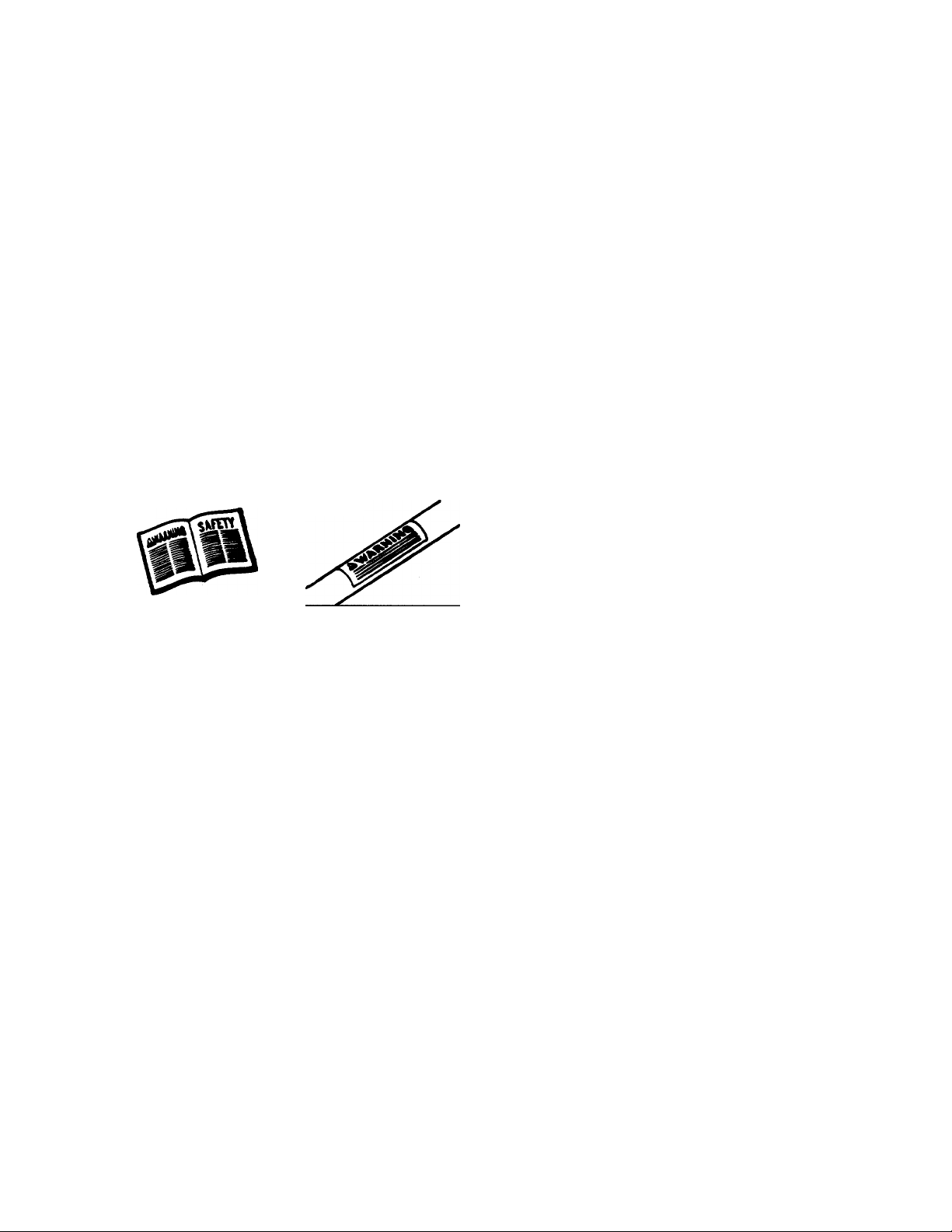
Restrict the use of this power machine to persons who read,
understand and follow the warnings and instructions in this
manual and on the machine.
WARNING — YOUR RESPONSIBILITY
Page 4
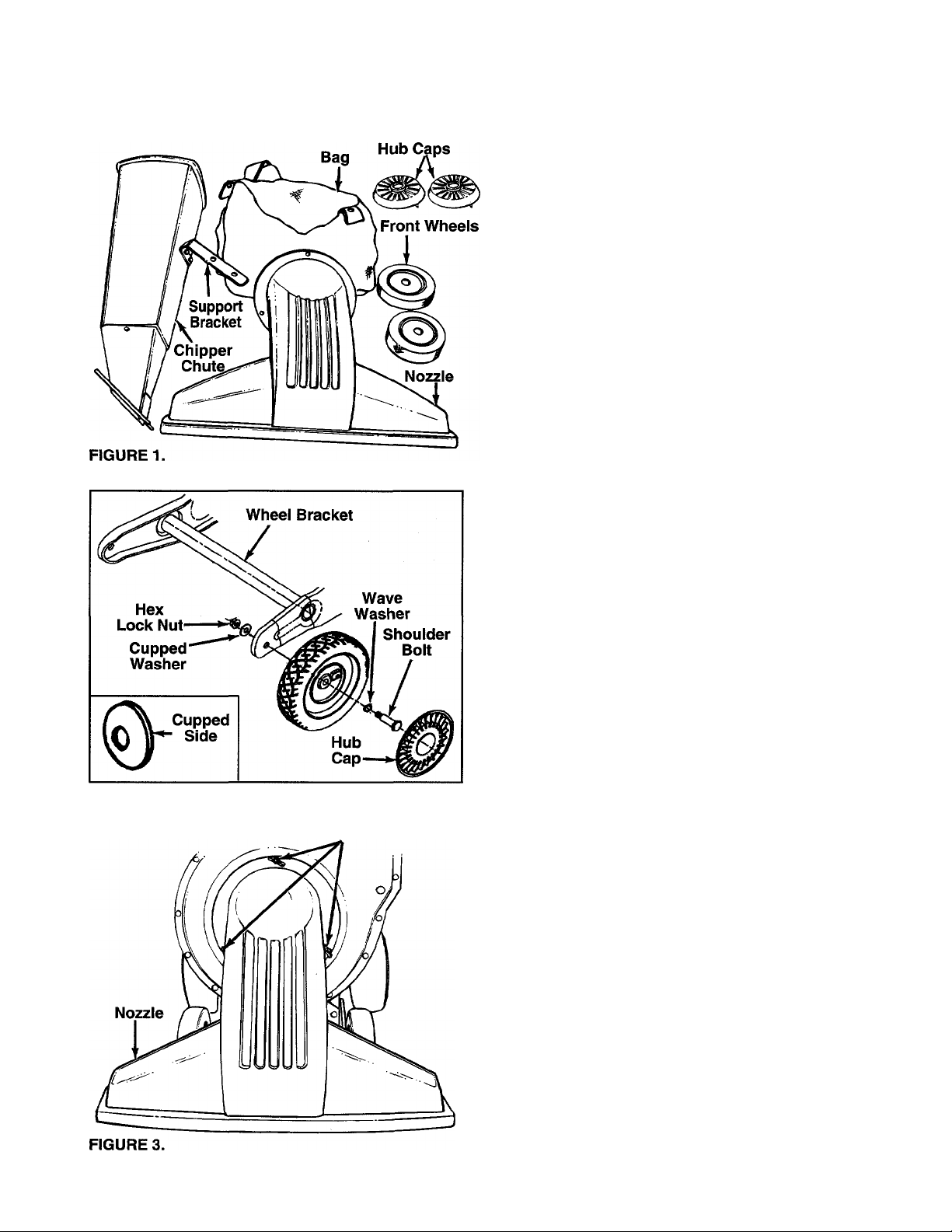
FIGURE 2.
ASSEMBLY INSTRUCTIONS
IMPORTANT: This unit is shipped WITHOUT
GASOLINE or OIL in the engine. After assembiy,
see operation section of this manuai for proper
fuei and engine oil recommendations.
NOTE: To determine right and left hand sides of your
chipper-vacuum, stand behind and face the unit
(Refer to figure 7).
Your chipper-vacuum has been completely assembled
at the factory except for the front wheels, hub caps,
nozzle, chipper chute, support bracket and bag. A pair
of safety glasses are also included in the carton.
TO REMOVE CHIPPER-VACUUM FROM CARTON
Cut the corner of the carton. Remove ail packing
inserts and loose parts. Push down on handle to lift
front of chipper-vacuum, and roil chipper-vacuum out
of the carton. Make certain ali parts and iiterature
have been removed before the carton is discarded.
TOOLS REQUIRED FOR ASSEMBLY
(1) 3/4" Open End Wrench
(2) 1/2" or Adjustable Wrenches
(1) 9/16" Wrench
(1) Funnel
LOOSE PARTS IN CARTON (See Figure 1)
(2) Front Wheels (1) Bag
(2) HubCapst (1) Shift Knobt
(1) Nozzle (1) Tamper Plugt
(1) Chipper Chute (i) Safety Glassesf
(1) Support Bracket
tNot Shown
ATTACHING THE FRONT WHEELS
1. Tiit unit backward so that it rests on the handle
(place a piece of the carton under handle to avoid
scratches). Remove the cardboard packing
material around the wheel brackets.
2. Remove the hex lock nuts and shoulder bolts
Wing Nuts
from the front of the wheel brackets. See figure 2.
3. Place wave washer on shoulder bolt. Insert
shoulder bolt through wheel, with the head of the
shoulder bolt through the flat side of the wheel.
4. Assemble wheel to outside of wheel bracket.
Secure with cupped washer (cupped side of
washer goes against the bracket) and hex lock
nut. Tighten.
5. Aiign the four tabs on the hub caps with the four
hoies in the wheei. Press in each tab until it locks
in place. The hub cap edges must be flush with
the wheei rim when instailed properly.
AHACHING THE NOZZLE (See figure 3)
1. Remove the three plastic wing nuts from the front
of the chipper-vacuum. Place the nozzle in posi
tion over the three weld studs. Secure with the
wing nuts just removed.
2. Set unit in upright position.
Page 5

jpport
racket
FIGURE 4.
FIGURE 5.
Upper Handle washers and Nuts
Lou^ Handle
Hex Bolts, Flat
M / Lociv ,
/ Nuts (
Drive
ATTACHING THE CHIPPER CHUTE AND
SUPPORT BRACKET (See figure 4)
1. Remove the two hex lock nuts from the hex bolts
which secure the right side of the upper handle to
the lower handle. Leave bolts and washers in
place.
2. Remove three cupped washers and 5/16" hex
nuts from the weld studs beside the opening on
the right side of the chipper-vacuum.
3. Place the chipper chute in position over the weld
studs (slot goes at the bottom). Secure with
cupped washers and hex nuts just removed. Only
tighten the three nuts one or two threads for ease
of further assembly.
NOTE: Cupped side of the washer goes against the
chipper chute. See figure 2 to identify cupped side of
washer.
4. Remove the two hex bolts, flat washers and nuts
which are attached to the support bracket.
5. Attach the support bracket to the bottom of the
chipper chute loosely using the hardware
removed previously. HEADS OF THE HEX
BOLTS AND WASHERS GO TO THE INSIDE OF
THE CHIPPER CHUTE.
6. Place the support bracket over the two bolts in
the handle. Pushing UP on the chipper chute will
aid the alignment of the holes in the support
bracket with the bolts in the handle.
7. Tighten all hardware securely on the chipper
chute, support bracket and handle.
ATTACHING THE CLUTCH CABLE
The clutch cable has been assembled at the factory.
Loosen the hex nuts at the cable bracket. Hook the
“Z” end of the cable into the drive clutch handle from
the outside to the inside as shown in figure 5A. Pliers
will aid in assembly.
CLUTCH CABLE ADJUSTMENT
Adjust the hex nuts at the cable bracket so there is no
slack in the cable, but the cable is NOT tight. Do not
overtighten the cable. See figure 5B.
To check the clutch adjustment, proceed as follows.
1. Push the chipper-vacuum backward and forward
with the drive clutch handle released. It should
move freely.
If it does not, loosen both hex nuts at the cable
bracket. See figure 5B. Turn bottom nut counter
clockwise to loosen the cable.
2. Engage the drive clutch handle (hold against
upper handle), and try to push chipper-vacuum
backward and forward. The wheels should lock
up.
If the wheels do not lock up, loosen both hex nuts
at the cable bracket. Turn bottom nut clockwise to
tighten the cable.
3. Recheck adjustment. Tighten both hex nuts when
correct adjustment is reached.
Page 6

ATTACHING THE BAG
1. Place bag inside of handie assembly. Slip the
opening on the bag over the discharge chute,
making certain it is over the rib on the discharge
chute. See figure 6.
2. Place the four straps on the top of the bag over
upper handle, hooking them on studs. See figure
7. Be sure the bag goes under the drive dutch
handle.
3. Squeeze the clamp on the drawstring, and puli
the drawstring tight. Release the clamp.
INSTALLING THE SHIFT KNOB
Remove the cardboard protecting the threads. Thread
the shift knob onto the end of the shift lever.
OPERATION
CONTROLS (See figure 8)
SHIFT LEVER
The shift lever may be moved into one of eight posi
tions. Run engine with throttle in the fast position. Use
the shift lever to determine ground speed.
Forward—one of six speeds. Position number one (1)
is the slowest. Position number six (6) is the fastest.
Reverse—two reverse (R) speeds. “R” (all the way to
the right) is the faster of the two.
DRIVE CLUTCH HANDLE
Squeezing the drive clutch handle against the upper
handle engages the wheel drive. Release the drive
clutch handle to stop the forward drive.
Shift
GAS AND OIL FILL-UP
Service the engine with gasoline and oil as
instructed in the separate engine manual packed with
your chipper-vacuum. Read instructions carefully.
NOTE: Your chipper-vacuum is shipped without oii;
however, a smaii amount of oii may be present from
the factory. Do not overfiii.
WARNING: Never fill fuel tank indoors,
with engine running or while engine is
A
TO START ENGINE
IMPORTANT: If unit shows any sign of motion with
the clutch handle disengaged, shut engine off immedi
ately. Readjust as instructed in the “Clutch Cable
Adjustment” section of the Assembly Instructions.
A
1. Attach spark plug wire to spark plug.
2. Make certain drive clutch handle is in the disen
3. Move choke lever on engine to CHOKE position.
4. Move throttle control lever on engine to FAST
5. Place one foot on the left rear wheel to prevent
6. Grasp starter handle and pull rope out slowly until
NOTE: A noise wiil be heard when finding the start of
the compression cycie. This noise is caused by the
fiaiis and fingers which are part of the shredding
mechanism faiiing into piace, and shouid be expect
ed. in addition, the fiaiis and fingers wili be noisy after
the engine is started, untii the impeiier reaches fuii
speed.
hot. Do not smoke when filling fuel tank.
WARNING: Be sure no one other than the
operator is standing near the chippervacuum while starting or operating. Do
not operate this chipper-vacuum unless
the nozzle, discharge chute and bag have
been properly installed.
gaged (released) position.
(A warm engine may not require choking.)
position.
the unit from skidding while starting.
engine reaches start of compression cycle (rope
wiirpull slightly harder at this point). Let the rope
rewind slowly.
Page 7

7. Pull rope with a rapid, continuous, full arm stroke.
Keep a firm grip on starter handle. Let rope
rewind slowiy. Do not let starter handle snap back
against starter.
8. Repeat instructions 6 and 7 until engine fires.
When engine starts, move choke control gradual
ly to RUN position.
TO STOP ENGINE
1. To stop engine, move throttie control lever to OFF
position.
2. Disconnect spark plug wire and ground to prevent
accidental starting while equipment is unattended.
IMPORTANT: The vacuum bag may have an air
escape located on the upper left hand side. See figure
9. The air escape can be opened if the vacuum is
operated in wet, sandy or muddy conditions.
The bag may be emptied using the large zipper as
shown in figure 9. Be certain the zipper is closed
when operating the unit.
HOW TO USE THE CHIPPER
Do not attempt to shred or chip any material other
than vegetation found in a normal yard (i.e., branches,
leaves, twigs, etc.). Material such as stalks or heavy
branches up to 3" in diameter may be fed into the
chipper chute. See figure 10.
WARNING: Material up to a maximum of
3" in diameter may be fed into the
A
chipper chute. Do not attempt to shred or
chip any material larger than 3" in diame
ter. Personal injury or damage to the
machine could result.
TO ENGAGE DRIVE
iMPORTANT: Always release the drive ciutch han-
die before moving the shift iever.
With the engine running near top speed, move shift
lever into one of the six FORWARD positions or two
REVERSE positions. Select a speed appropriate for
the conditions that exist. Use the slower speeds until
you are familiar with the operation of the chipper-
vacuum.
To engage the wheel drive, hold the drive clutch
handle against the chipper-vacuum handle. Releasing
the drive clutch handle stops the wheels from driving.
Release the drive clutch handle to slow down when
negotiating an obstacle, making a turn or stopping.
Engage slowly to prevent front wheels from lifting up.
FIGURE 10.
IMPORTANT: There is a flail screen located inside
the housing in the discharge area. If the flail screen
becomes clogged, remove and clean as instructed in
the Maintenance section on page 9.
For best performance, it is important to keep the
chipper blades sharp. Refer to Maintenance section,
page 9. If the composition of the material being dis
charged changes (becomes stringy, etc.) or if the rate
at which the material is discharged slows down
considerably, it is iikely that the chipper blades are
dull and need to be sharpened or replaced.
ADJUSTMENTS
WARNING: Do not at any time make any
adjustment to the unit without first stop
A
HEIGHT ADJUSTMENT
The height adjustment knob is located on the right
hand side of the chipper-vacuum. See figure 11. Turn
the knob clockwise to raise the nozzle. Turn the knob
counterclockwise to lower. (Be careful not to turn
knob too far—rod could come out of ferrule.)
ping engine and disconnecting spark
plug wire.
Page 8

The best height for the nozzle will vary according to
the conditions. Adjust the height of the nozzle to find
the setting which gives the best performance for the
operating conditions. In general, raise the nozzle to
vacuum a thick layer of leaves; lower the nozzle for
smooth surfaces.
Shift Lever
6th Position
FIGURE 12.
CARBURETOR ADJUSTMENT
WARNiNG: if any adjustments are made
to the engine whiie the engine is running
A
Minor carburetor adjustment may be required to com
pensate for differences in fuel, temperature, altitude
or load. Do not make unnecessary adjustments.
Factory settings are satisfactory for most applications
and conditions. If adjustment is needed, refer to the
separate engine manual packed with your chippervacuum.
NOTE: A dirty air cleaner will cause engine to run
rough. Be certain air cleaner is clean and attached to
the carburetor before adjusting carburetor.
CLUTCH CABLE ADJUSTMENT
To adjust the clutch cable, refer to the “Clutch Cable
Adjustment” section of Assembly Instructions.
SHIFT RDD ADJUSTMENT
If the shift rod needs adjustment to obtain forward or
reverse correctly, proceed as follows. See figure 12.
3.
4.
5.
(e.g., carburetor), keep ciear of aii mov
ing parts. Be carefui of heated surfaces
and muffier.
Remove the bag from the unit.
Remove the hairpin clip and flat washer from the
upper end of the shift rod. Pull the ferrule out of
the hole in the shift lever. (Make certain wave
washer remains in place on the ferrule.)
Place the shift lever in 6th position (all the way to
the left).
Push down on the shift rod. Thread the ferrule up
or down the shift rod until the ferrule lines up with
the upper hole in the shift lever.
Secure ferrule to shift lever with flat washer and
hairpin clip.
MAINTENANCE
WARNING: Always stop engine and dis
connect spark plug wire before cleaning,
A
LUBRICATIDN
Wheels—Rear wheels are provided with light oil bear
ings. Place a few drops of SAE 30 oil on each bearing
once a season.
Height Adjustment Mechanism—Lubricate the pivot
points on the height adjustment mechanism once a
season using a light oil.
CLEANING
Clean the chipper-vacuum thoroughly after each use.
Wash the bag periodically with water. Allow to dry
thoroughly in the shade. Do not use heat.
ENGINE
Refer to the separate engine manual for engine main
tenance instructions.
Maintain engine oil as instructed in the separate
engine manual packed with your unit. Read and follow
instructions carefuliy.
Service air cleaner every 25 hours under normal con
ditions. Clean every few hours under extremely dusty
conditions. Poor engine performance and flooding
usually indicates that the air cleaner should be ser
viced. To service the air cleaner, refer to the separate
engine manual packed with your unit.
The spark plug should be cleaned and the gap reset
once a season. Spark plug replacement is recom
mended at the start of each season; check engine
manual for correct plug type and gap specifications.
lubricating or performing any repairs or
maintenance.
Page 9

Clean the engine regularly with a cloth or brush.
Keep the cooling system (blower housing area) clean
to permit proper air circulation which is essential to
engine performance and life. Be certain to remove all
dirt and combustible debris from muffler area.
REMOVING THE FLAIL SCREEN
If the discharge area becomes clogged, remove the
flail screen and clean area as follows.
1. Stop the engine. Make certain the chippervacuum has come to a complete stop. Disconnect
the spark plug wire before unclogging the
discharge chute.
2. Remove the vacuum bag from the unit.
3. Remove the four self-tapping screws from the
bottom of the discharge chute, and the hex bolt,
flat washer and hex nut from the top. Remove the
discharge chute assembly. See figure 13.
Discharge
Chute
Assembly
5. Clean the screen by scraping or washing with
water. Reinstall the screen.
NOTE: Be certain to reassemble the flail screen with
the curved side down as shown in figure 14.
SHARPENING OR REPLACING CHIPPER BLADES
1. Disconnect the spark plug wire and move away
from the spark plug.
2. Remove the flail screen as instructed in the previ
ous section.
3. Remove the plastic belt cover on the front of the
engine by removing the two self-tapping screws.
See figure 15.
Belt
Cover
Self-Tapping
Screws
Hex Bolt
=lat Washer
Hex Nut
Seif-Tapping
Screws
FIGURE 13.
4. Remove the two hex bolts and hex nuts which
extend through the housing. Lift the flail screen
from inside the housing. See figure 14.
1
1J1
FIGURE 15.
4. Remove the access plate by removing two hex
lock nuts. See figure 16.
5. Locate one of the chipper blades in the access
plate opening by rotating the impeller assembly
by hand. Remove the blade using a 3/16" alien
wrench on the outside of the blade and 1/2"
wrench on the impeller assembly, inside the
housing.
Page 10

6. Remove the other blade in the same manner.
Replace or sharpen blades. If sharpening, make
certain to remove an equal amount from each
blade. Reassemble in reverse order.
NOTE: Make certain blades are reassembled with the
sharp edge facing upward, as viewed from the access
plate opening.
CHANGING THE FRICTION WHEEL RUBBER
The rubber on the friction wheel is subject to wear
and should be checked after 50 hours of operation,
and periodically thereafter. Replace friction wheel
rubber if any signs of wear or cracking are found.
1. Drain the gasoline and oil from the chipper-
vacuum.
2. Tip the unit backward so it rests on the handles.
3. Remove the frame cover by removing eight self
tapping screws from underneath the chippervacuum. See figure 17.
4. Remove the gear shaft from the unit by removing
the hex bolts, lock washers and flat washers from
each side of the frame. See figure 18. Hold the
friction wheel assembly, and slide the gear shaft
out of the unit toward the right side.
5. Remove the six screws from the friction wheel
assembly (three from each side). Remove the
friction wheel rubber from between the friction
wheel plate.
6. Reassemble new friction wheel rubber to the fric
tion wheel assembly, tightening the six screws in
rotation and with equal force.
7. Slide the friction wheel assembly up onto the shift
mechanism, then slide the gear shaft back into
the unit. Reassemble in reverse order.
8. Readjust the clutch cable. Refer to adjustment
section.
BELT REMOVAL AND REPLACEMENT
WARNING: Disconnect the spark plug
A
1. Remove the plastic belt cover on the front of the
2.
3. Tip the unit backward so that it rests on the
4.
5.
wire and move away from the spark plug.
engine by removing two self-tapping screws.
Refer to figure 14.
Drain the gasoline and oil from the chippervacuum.
handles.
Remove the frame cover by removing eight self
tapping screws from underneath the chippervacuum. Refer to figure 17.
Remove the idler pulley bracket as follows. (See
figure 19.)
a. Take the tension off thé belt by pivoting the
idler pulley toward you, and line up the holes in
the idler bracket assembly. Insert a nail or simi
lar object through the holes to hold the idler
pulley in this position.
b. Remove three self-tapping screws, and lift off
the idler bracket assembly.
10
Page 11

6. Remove the hex bolt and lock washer from the
engine pulley. See figure 19. Slip the engine pul
ley off the engine shaft, and remove the belt from
the pulley.
7. Loosen the nut on the stop bolt until there is
clearance between the support bracket and the
friction wheel disc. See figure 20.
8. Slip the belt between the friction wheel and fric
tion wheel disc. Remove and replace belt.
Reassemble following instruction in reverse
order.
NOTE: The support bracket must rest on the stop bolt
after the new belt has been assembled.
Support
OFF-SEASON STORAGE
The following steps should be taken to prepare your
chipper-vacuum for storage.
1. Remove all dirt from exterior of engine and equip
ment.
2. Refer to engine manual for correct engine storage
instructions.
3. Wipe unit with an oiled rag to prevent rust (use a
light oil or silicone), especially if storing in an
unventilated or metal storage shed.
4. Store in a dry, clean area. Do not store next to
corrosive materials, such as fertilizer.
OPTIONAL EQUIPMENT
Hose Attachment Kit Model 290-005 is available as
optional equipment.
Model No. -315B
Spark Plug J-8C
Air Filter Element
Air Pre-Cleaner 35881
Engine Oil (SAE 30)
Chipper Blade (Standard)
Chipper Blade (Tooled Steel)
Bag
Safety Glasses 723-0400
Vacuum Hose Kit (Optional)
33268
737-0208
(26 oz. req’d.)
781-0490
742-0544
764-0472
290-005
The only way to ensure the performance of your
product is to use original equipment parts and
accessories, which are designed and engineered to
exacting specifications. When you substitute, you take
a chance on quaiity, reliabiiity, safety and per
formance. Use originai equipment parts—See your
iocal service deaier.
11
Page 12

TROUBLE SHOOTING
PROBLEM
Engine fails to start
Loss of power;
operation erratic
Engine overheats
Too much vibration
Unit does not
discharge
POSSIBLE CAUSE(S)
1. Spark plug wire disconnected.
2. Fuel tank empty, or stale fuel.
3. Faulty spark plug.
1. Spark plug wire loose.
2. Unit running on CHOKE.
3. Blocked fuel line or stale fuel.
4. Water or dirt in fuel system.
5. Carburetor out of adjustment.
6. Dirty air cleaner.
1. Carburetor not adjusted
properly.
2. Engine oil level low.
Loose parts or damaged
impeller.
1. Discharge chute clogged.
2. Foreign object lodged in impeller.
3. Vacuum bag is full.
CORRECTIVE ACTION
1. Connect wire to spark plug.
2. Fill tank with clean, fresh fuel.
3. Clean, adjust gap or replace.'
1. Connect and tighten spark plug wire.
2. Move choke lever to OFF position.
3. Clean fuel line; fill tank with clean
fresh gasoline.
4. Disconnect fuel line at carburetor to drain fuel
tank. Refill with fresh fuel.
5. Adjust carburetor.f
6. Service air cleaner.f
1
. Adjust carburetor.f
2. Fill crankcase with proper oil.
Stop engine immediately and disconnect
spark plug wire. Tighten all bolts and nuts.
Make all necessary repairs. If vibration continues,
have unit serviced by an authorized service
dealer.
1. Stop engine immediately and disconnect
spark plug wire. Clean flail screen and inside
of housing. See Maintenance section of this
manual.
2. Stop engine immediately and disconnect
spark plug wire. Remove lodged object.
3. Empty bag.
Rate of discharge
slows considerably or
composition of
discharged material
changes
Chipper blades dull.
Sharpen or replace chipper blades.
tRefer to the engine manual packed with your unit.
NOTE: For repairs beyond the minor adjustments listed above, please contact your nearest authorized service dealer.
For Replacement Parts, Contact:
SERVICE DEPARTMENT • P.O. BOX 368022 • CLEVELAND, OHIO 44136-9722
 Loading...