

Page 1

OUTDOOR POWER EQUIPMENT
for all seasons
.75
26" and 33"
SNOW
THROWERS
Model Numbers
315-800-000
315-860-000
315-960-000
Important:
Read Safety Rules and
Instructions Carefully
V
PRINTED IN U.S.A.
Thank you for purchasing
an American-built product.
FORM NO. 770-3960
Page 2

INDEX
Safe Operation Practices.......................................................3
Assembly Instructions...........................................................4
Operation.................................................................................9
Adjustments.........................................................................11
Lubrication............................................................................14
Instructions given with this symbol are for per
A
sonal safety. He sure to follow them.
r
♦
♦
♦
♦
♦
♦
♦
♦
For one year from the date of original retail purchase, MTD PRODUCTS INC will either
repair or replace, at its option, free of charge, F.O.B. factory or authorized service firm, any
part or parts found to be defective in material or workmanship. Transportation charges for
the movement of any power equipment unit or attachment are the responsibility of the pur
chaser. Transportation charges fot any parts submitted for replacement under this warran
ty must be paid by the purchaser u iless such return is requested by MTD PRODUCTS INC.
This warranty will not apply to an> part which has become inoperative due to misuse, ex
cessive use, accident, neglect, imaroper maintenance, alterations, or unless the unit has
been operated and maintained in accordance with the instructions furnished. This warran
ty does not apply to the engine, me tor, battery, battery chargeror component parts thereof.
Please refer to the applicable mar ufacturer’s warranty on these items.
LIMITED WARRANTY
Maintenance .........................................................................15
Off-Season Storage..............................................................18
lilustrated Parts
Parts Lists.........................................................21,23,25,27,29
Parts information...................................................BackCover
...............................................
20,22,24,26,28
♦
♦
♦
♦
♦
♦
♦
t
♦
♦
♦
♦
♦
♦
V
This warranty will not apply where the unit has been used commercially.
Warranty service is available through your local authorized service dealer or distributor. If
you do not know the dealer or distr butor in your area, please write to the Customer Service
Department of MTD.
The return of a complete unit will lot be accepted by the factory unless prior written per
mission has been extended by MID.
This warranty gives you specific
from state to state.
;gal rights. You may also have other rights which vary
♦
♦
♦
♦
♦
♦
J
Page 3

WARNING
AC
To reduce the potential for any injury, comply with the following safety instructions. Failure to comply
with the instructions may result in personal injury.
SAFE OPERATION PRACTICES FOR SNOW THROWERS
TRAINING
1. Read this Owner’s manual carefully. Be thoroughly
familiar with the controls and proper use of the
equipment. Know how to stop the unit and dis
engage the controls quickly.
2. Never allow children to operate equipment. Never
allow adults to operate equipment without proper
instructions.
3. No one should operate this unit while intoxicated or
while taking medication that impairs the senses or
reactions.
4. Keep the area of operation clear of all persons,
especially small children and pets.
5. Exercise caution to avoid slipping or falling, espe
cially when operating in reverse.
PREPARATION
1. Thoroughly inspect the area where the equipment is
to be used and remove all door mats, sleds, boards,
wires and other foreign objects.
2. Disengage all clutches and shift into neutral before
starting engine.
3. Do not operate equipment without wearing ade
quate winter outer garments. Wear footwear which
will improve footing on slippery surfaces.
4. Handle fuel with care. It is highly flammable.
(A) Use approved fuel container.
(B) Never add fuel to a running engine or hot
engine.
(C) Fill fuel tank outdoors with extreme care. Never
fill fuel tank indoors.
(D) Replace gasoline cap securely and wipe up
spilled fuel.
5. Use a grounded three wire plug-in for all units with
electric drive motors or electric starting motors.
6. Adjust collector housing height to clear gravel or
crushed rock surface.
7. Never attempt to make any adjustments while
engine is running (except where specifically recom
mended by manufacturer).
8. Let engine and machine adjust to outdoor tem
perature before starting to clear snow.
OPERATION
1. Do not put hands or feet near rotating parts. Keep
clear of discharge opening at all times.
2. Exercise extreme caution when operating on or
crossing gravel drives, walks, or roads. Stay alert for
hidden hazards or traffic. Do not carry passengers.
3. After striking a foreign object, stop the engine,
remove wire from spark plug, and thoroughly in
spect the snow thrower for any damage. Repair the
damage before restarting and operating the snow
thrower.
4. If the snow thrower should start to vibrate abnormal
ly, stop the engine and check immediately for the
cause. Vibration is generally a warning of trouble.
5. Stop engine whenever you leave the operating posi
tion, before unclogging the collector/impeller hous
ing or discharge guide, and making any repairs, ad
justments, or inspections.
6. Take all possible precautions when leaving the vehi
cle unattended. Disengage the power take-off, lower
the attachment, shift into neutral, set the parking
brake, stop the engine, and remove the key.
7. When cleaning, repairing, or inspecting, make cer
tain collector/impeller and all moving parts have
stopped. Disconnect spark plug wire and keep away
from plug to prevent accidental starting.
8. Do not run engine indoors, except when starting
engine and transporting snow thrower in or out of
building. Open doors. Exhaust fumes are dan
gerous.
9. Do not clear snow across the face of slopes. Exer
cise extreme caution when changing direction on
slopes. Do not attempt to clear steep slopes.
10. Never operate snow thrower without guards, plates,
or other safety protection devices in place.
11. Never operate snow thrower near glass enclosure,
automobiles, window wells, drop off, etc., without
proper adjustments of s iow thrower discharge
angle. Keep children and p ¡ts away.
12. Do not overload machine c< r acity by attempting to
clear snow at too fast a rate
13. Never operate machine at h
slippery surfaces. Use care
14. Never direct discharge a
anyone in iron. ^nit.
15. Disengage power to collector/impeller when
transporting or not in use.
16. Use only attachments and accessories approved by
the manufacturer of snow thrower (such as wheel
weights, counter weights, cabs, etc.).
17. Never operate the snow thrower without good
visibility or light. Always be sure of your footing and
keep a firm hold on the handles. Walk, never run.
MAINTENANCE AND STORAGE
1. Check shear bolts, engine mounting bolts, etc., at
frequent intervals for proper tightness to be sure
equipment is in safe working condition.
2. Never store machine with fuel in the fuel tank inside
a building where open flame or spark are present.
Allow engine to cool before storing in any
enclosure.
3. Always refer to owner’s guide instructions for im
portant details if snow thrower is to be stored for an
extended period.
4. Run machine a few minutes after throwing snow to
prevent freeze up of collector/impeller.
transport speeds on
in backing,
ystanders or allow
Page 4

This owner’s manual covers various
models of snow throwers. The uni
illustrated may be different thar
your unit.
This unit is shipped WITHOUT GAS
OLINE or OIL. After assembly, see
separate engine manual for propei
fuel and engine oil recommenda
tions.
FIGURE 3.
NOTE
NOTE
ASSEMBLY
NOTE
Reference to right hand or left hand
side of machine is observed from
the operating position.
Tools Required for Assembly:
9/16" Wrench
1/2" Wrench
7/16" Wrench
or One Adjustable Wrench
Loose Parts in Carton:
(1) Handle Assembly
(1) Chute Assembly
(1) Parts taped together which include;
(1) Drive Clutch Rod Assembly
(1) Auger Rod
-------
(1) Shift Rod
(1) Chute Crank Assembly
Contents of Hardware Pack:
A
(2) Hex Bolts 3/8-16 x 2” Long
B
(3) Belleville Washers 3/8" I.D.
C
(2) Hex Nuts 5/16-18 Thread
D
(1) Belleville Washer 5/16" I.D.
E
(3) Chute Flange Keepers
F
(6) Hex Lock Nuts V4-20 Thread
G
(1) Flat Washer 3/8" I.D. x 5/8" O.D.
H
(1) Large Flat Washer
I
(1) Hex Bushing
J
(1) Cotter Pin
K
(1) Hairpin Cotter
L
(1) Compression Spring
-M
(1) Elastic Lock Nut 3/8-24 Thread
N
(2) Ignition Keys
O
(2) Hex Bolts 5/16-18 x 1%" Long*
P
(2) Hex Lock Nuts 5/16-18 Thread*
G
(1) Shift Lever
the augers are secured to the spiral shaft with
two hex bolts and hex lock nuts (see ref. nos. 40
and 50 on page 24). If you hit a foreign object or
ice jam, the snow thrower is designed so that the
hex bolts will shear. Two replacement hex bolts
and nuts are provided in the hardware pack for
your convenience. Store in a safe place until
needed.
1. Remove snow thrower and all parts from the
carton. Make certain that all loose parts and
literature have been removed before the car
ton is discarded.
Extend throttle control assembly which is at
tached to engine at rear of the snow thrower
and place on floor. Be careful not to bend or
kink control wire.
To assemble the handle, loosen one self
tapping screw and belleville washer on each
side of the unit. See figure 3. A 9/16" wrench
or adjustable wrench is required.
Page 5

Hex Bolt (A)
Belleville
Washer (B)
FIGURE 4.
Slide the slotted end of the handles under the
4.
belleville washers on the self-tapping screws
which were loosened in step 3.
Secure the upper hole in the handles with
5.
belleville washers (B) (cupped side against the
■handles) and hex bolts (A). See figure 4. Do not
tighten at this time.
6. Thread one hex nut (C) onto the eyebolt on the
chute crank assembly until there is approx
imately VA" of threads showing between the
— nut and the head of the eyebolt. See figure 5.
Place the eyebolt into the hole in the left han
7.
dle and handle panel. See figure 5. Secure
with belleville washer (D) (cupped side against
the handle panel) and hex nut (C). Tighten
securely.
Tighten securely all bolts and nuts on the han
8
dle panel and all four bolts which secure the
handles to the frame.
Grease the chute opening.
9.
Place chute assembly over chute opening,
10.
with the chute facing the front of the unit.
Place chute flange keepers (E) beneath lip of
chute assembly. Secure with hex lock nuts (F)
as shown in figure 6. Tighten with a 7/16"
wrench, then back off V4 turn to allow easier
movement.
Page 6

FIGURE 7.
11. Place hex bushing (I) into bracket beside the
chute assembly. Position the hex bushing so
the hole in the bushing is close to the chute
-------
assembly. See figure 7.
12. Place flat washer (G) on the end of the chute
crank. Insert the chute crank into the hole in
the hex bushing so that the spiral on the chute
crank engages the teeth on the chute assem
bly. Place large flat washer (H) on the end of
the chute crank. Insert cotter pin (J) into hole
in the end of chute crank. Secure by bending
the ends of cotter pin in opposite directions.
13. Assembie the throttie control to the handle
panel as follows.
A. Hold the throttle control assembly
beneath the handle panel. Turn the control
sideways and insert the lever up through
the wide portion of the slot on the handle
panel. See figure 8A.
B. After the end of the lever is through the
slot, turn and then tip the control forward
as shown in figure 8B to slide it through
the slot.
FIGURE 8.
NOTE
The lever must be all the way to the
back of the control housing as
shown in figure 8B.
C. Push the control back into the slot in the
handle panel and press in place. Be certain
the control is locked securely into the slot.
A
14.
---
Place shift lever (Q) through slot in handle
panel, making sure flared edge of shift lever
faces the detents on handle panel. Place the
hole in the end of the shift lever over the han-
-------
die panel weld bolt. See figure 9.
Page 7

FIGURE 10.
15. Place the shift rod through the slot in the bot
tom frame cover. Thread rod into ferrule. See
■figure 10.
16. Move the shifting rod up or down until the
-------
drive clutch bracket shows in the locating
slot. See figures 10 and 11.
FIGURE 11.
FIGURE 12.
17.
-----
Place the shift lever in neutral (N) position.
Screw the shift rod in or out until it fits into
the hole in the shift lever (drive clutch must
still be showing in the locating slot). When
shift rod is adjusted to the correct length, in
sert the end into the hole in the shift lever.
Secure with hairpin cotter (K) as shown in
-------
figure 12.
Page 8
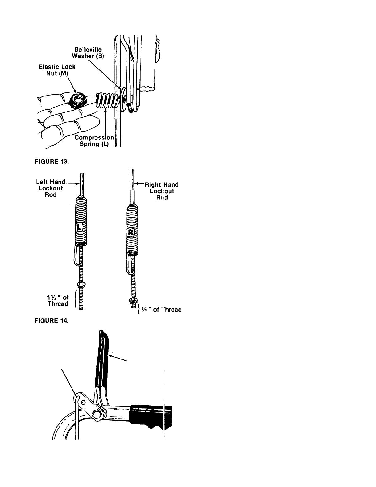
18. Secure with belleville washer (B) (cupped side
goes against shift lever), compression spring
(L) and elastic lock nut (M). See figure 13.
Tighten lock nut until compression spring
holds the shift lever into detent slot on handle
panel.
19.
The lockout rods are labeled “L” and “R” for
the left and right hand sides of the unit.
Approximate initial settings for the lockout
rods are as follows; The left hand lockout rod
for the drive clutch should have approximately
IV2 inches of thread showing below the nut.
The right hand lockout rod for the auger
clutch should have approximately Va inch of
thread showing below the nut. See figure 14.
FINAL ADJUSTMENT MUST BE MADE AS
DESCRIBED IN STEPS 21 AND 22. If the left
hand lockout rod is not adjusted correctly, the
shift lever cannot be shifted past neutral. If
the right hand lockout rod is not adjusted cor
rectly, the augers will not stop rotating.
Hook in Lockout
Rod is to the
Outside of Unit
FIGURE 15.
Clutch
Grip
20. Hook the right hand lockout rod (labeled “R”)
into the hole provided in the right hand clutch
grip (auger clutch). Hook the left hand lockout
rod (labeled “L”) to the left hand clutch grip
(drive clutch). See figure 15. The hook is to the
outside of the unit.
Page 9
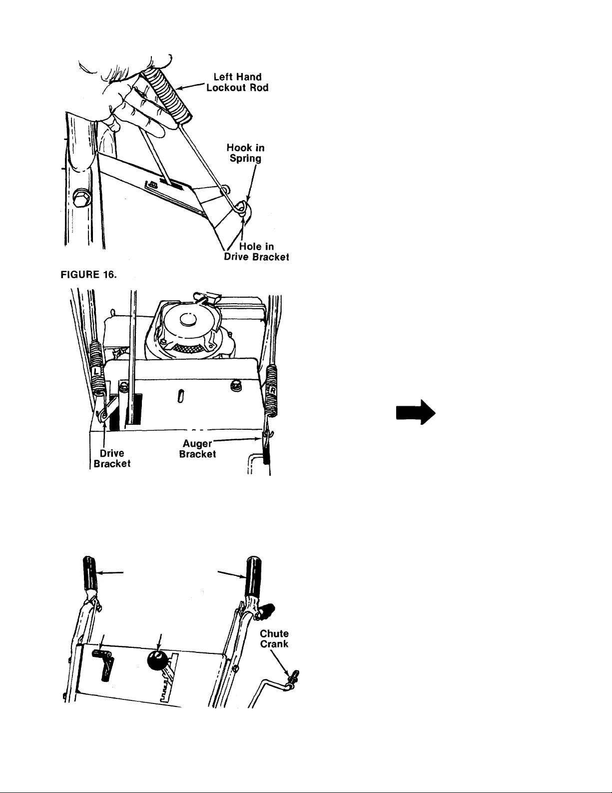
21. Swing the left hand lockout rod down and
simply hold it beside the drive bracket. Do not
pull on spring. Do not move bracket. The hook
on the end of the spring must line up with the
center of the hole in the drive bracket. See
-------figure 16.
If it does not, adjust the nut on the lockout rod
until the hook on the spring aligns with the
hole in the bracket as shown in figure 16.
Hook spring into drive bracket. See figure 17.
22. Adjust the right hand lockout rod in the same
manner as the left hand lockout rod. Refer to
Step 21. When adjustment is correct, hook the
-------
spring into the auger bracket. See figure 17.
PNEUMATIC TIRE PRESSURE
The tires are over inflated for ship
ping purposes. Check pressure and
reduce to 15 to 20 p.s.i.
FIGURE 17.
OPERATION
CONTROLS
Auger Drive
Clutch Clutch
' Throttle Shift
Control Lever
NOTE
If the tire pressure is not equal
in both tires, the unit may pull to
one side or the other.
Shift Lever (See figures 18 and 19)
The shift lever is located on the left hand side of
handle panel. The shift lever may be moved into
one of eight positions. Run engine with throttle in
the fast position. Use the shift lever to determine
ground speed.
a. Center position (N)—“NEUTRAL."
b. Forward position—One of five (5) forward
speeds. Position number one (1) is the slowest.
Position number five (5) is the fastest.
FIGURE 18.
c. Rear position—Two reverse (R) speeds. “R”
nearest the neutral (N) position is the slower of
the two.
Page 10

FIGURE 19.
Throttle Control (See figures 18 and 20)
The throttle control is located on the righ hand
side of the handle panel. It regulates the speed of
the engine.
Drive Clutch (See figure 18)
The drive clutch is located on the left handle.
Squeeze the clutch grip to engage drive. Release
to stop.
Auger Clutch (See figure 18)
The auger clutch is located on the right handle.
Squeeze the clutch grip to engage the cugers.
Release to stop the snow throwing action.
Chute Crank (See figure 18)
The chute crank is located on left hand side of the
snow thrower.
To change the direction in which snow is th rown,
turn chute crank as follows:
1. Crank clockwise to discharge to the left.
2. Crank counterclockwise to discharge o the
right.
Safety Ignition Switch (See figure 21)
The ignition key must be inserted in the s witch
before the unit wili start. Remove the ignition key
when snow thrower is not in use.
FIGURE 20.
FIGURE 21.
STARTING INSTRUCTIONS
1. Remove dipstick. Fill crankcase with oil. Oil
level must be to full mark on dipstick. Refer to
separate engine manual packed with your
snow thrower.
2. Fill fuel tank with fresh, clean regular
gasoline.
WARNING
Ai
Never fill fuel tank indoors, with en
gine running or while engine is hot.
3. Attach spark plug wire to spark plug.
4. Insert ignition key (do not turn).
5. Place shift lever in “NEUTRAL” (N) position.
6. Place throttle control in “START” (fast) posi
tion.
WARNING
AC
Never run engine indoors or in en
closed poorly vented area. Engine
exhaust gases contain carbon mon
oxide: an odorless and deadly gas.
7. Start engine, following appropriate instruc
tions:
A. Cold engine start (engine has not been run
recently).
1. Turn choke knob to “full” position. See
figure 21.
2. Push primer two (2) or three (3) times.
See figure 21.
10
Page 11

NOTE
Additional priming may be required
(for initial start only) if temperature
is below 15° F.
3. Grasp the starter rope handle and pull
out rapidly. Return rope handle slowly.
Repeat until engine starts. If engine
fails to start, repeat steps 2 and 3 as
necessary until engine starts.
4. After engine starts, turn choke gradual
ly to “OFF” position.
B. Warm engine start (engine still warm from
recent running).
1. Grasp the starter rope handle and pull
out rapidly. Return rope handle slowly.
Repeat until engine starts.
2. If engine fails to start after a number of
attempts, choke engine. Repeat step
one until engine starts. After engine
starts, turn choke knob off gradually.
Ac WARNING {
TO ENGAGE DRIVE
1. With the engine running near top speed, move
shift lever into one of the five forward posi
tions or two reverse positions. Select a speed
appropriate for the snow conditions that exist.
Use the slower speeds until you are familiar
with the operation of the snow thrower.
2. Squeeze the drive clutch grip (located on the
left handle) and the snow thrower will move.
Release it and the drive motion will stop.
NOTE
NEVER move shift lever without
first releasing the drive clutch.
ADJUSTMENTS
Ac WARNING ^
NEVER attempt to clean chute or
make any adjustments while engine
is running.
After the snow blower has been in
operation, caution should be exer
cised in the area of the muffler and
surrounding surfaces.
TO STOP ENGINE
NOTE
Run engine for a few minutes before
stopping to help dry off any mois
ture which may have accumulated
on the recoil starter.
1. Move throttle control lever to “STOP” posi
tion or pull out ignition key.
2. Remove ignition key to prevent accidental
starting.
A
Disconnect spark plug wire from
spark plug and secure it so that it
cannot accidentally contact spark
plug. Observing this precaution will
reduce the possibility of unauthor
ized starting of engine while equip
ment is unattended.
CAUTION
CHUTE ASSEMBLY ADJUSTMENT
The distance snow is thrown can be changed by
adjusting the angle of the chute assembly. The
sharper the angle, the shorter the distance snow
is thrown. See figure 22.
To adjust chute assembly, loosen the hand knob.
Pivot the top of the chute assembly to position
desired. Retighten the hand knob.
11
Page 12

SKID SHOE ADJUSTMENT
The space between the shave plate aid the
ground can be adjusted for close snow removal by
placing skid shoes in the low position. Use middle
or high position when area to be cleared is
uneven. See figure 23.
To adjust skid shoes, loosen the four hex nuts and
carriage bolts. Move skid shoes to desired posi
tion. Retighten nuts and bolts securely.
H gh
Middle
L )w
FIGURE 23.
THROTTLE CONTROL ADJUSTMENT
If adjustment becomes necessary, the tirottle
control wire assembly can be reset as follc ws:
1. Loosen, but do not remove, screw securing
throttle control wire assembly at engine. See
figure 24.
2. Move throttle control lever on handle panel to
“FAST” position.
3. Move control lever on engine to full ope i posi
tion. Retighten screw to secure throttle con
trol wire assembly.
CARBURETOR ADJUSTMENT
WARNING
Ai
If any adjustments are made to the
engine while the engine is running
(e.g. carburetor), keep clear of all
moving parts. Be careful of heated
surfaces and muffler.
Minor carburetor adjustment may be required to
compensate for differences in fuel, temperature,
altitude and load.
Refer to the separate engine manual packed with
your unit for carburetor adjustment information.
DRIVE WHEELS (Model 800)
The wheels on the model 800 snow thrower may
be adjusted for three different methods of opera
tion. The adjustment is made by placing the klick
pins in one of two different holes on each side of
the unit. See figure 25.
1. Free Wheeling Operation—Place both klick
pins in the outside hole in the axle. This posi
tion allows easier movement when the engine
is not running.
2. Both Wheels Driving—Place both klick pins in
the hole in the hub next to the rim. This posi
tion is good for heavy snow as there is power
drive in both wheels.
3. One Wheel Driving —Place klick pin in the out
side axle hole on one side and in the hole in
the hub next to the rim on-the other. This posi
tion gives power drive to one wheel only, mak
ing the unit easier to maneuver.
FIGURE 24.
Hole in Hub
Next to Rim
Klick Pin
Outside Hole
in Axle
FIGURE 25.
12
Page 13

DRIVE WHEELS (Models 860 and 960)
Snow throwers model 860 and 960 are equipped
with a differential which makes the unit easy to
maneuver, it may be adjusted for two different
methods of operation. The adjustment is made by
placing the kiick pins in one of two different holes
on each side of the unit. See figure 25.
1. Differential Action —Place kiick pin in the out
side hole in the axle. This position allows easy
maneuvering when blowing light to medium
snow.
2. Straight Axle Action—Place kiick pin in the
hole in the hub next to the rim on the right
wheel. This position should be used when
blowing heavy snow or when greater traction
is needed (icy surfaces, etc.). The unit will be
more difficult to maneuver.
DRIVE AND AUGER CLUTCH ADJUSTMENTS
To adjust the drive or auger clutch, unhook the
spring from the drive or auger bracket. Refer to
steps 21 and 22 under Assembly Instructions for
proper adjustment.
SHIFT ROD ADJUSTMENT
To adjust the shift rod, place the shift lever in
neutral. Remove the cotter pin which secures the
shift rod to the shift lever. Adjust as specified in
step numbers 16 and 17 under Assembly Instruc
tions.
13
Page 14

LUBRICATION
SPECIFICATIONS:
Lubricate once a season or after every 25 h 3urs of
operation.
Oil—Use SAE 30 or equivalent.
Grease—Use automotive multi-purpose groase.
Lubricate chain once a season with enginii oil.
Grease Chute Opening Once
A Season
Engine—Remove oil fill plug and add oil until it is
to full mark on dipstick.
Change Oil—After first two (2) hours of operation
and every twenty-five (25) hours thereafter. Drain
oil from oil drain plug.
Use viscosity grade SAE 5W-30 or SAE 10W oil.
Capacity—Approximately 1V2 pints.
Differential (Models 860 and 960)
is sealed at the factory and does
not require checking. If dis
assembled for any reason, lubri
cate with 3/4 oz. of Plastilube #0.
Order part number 737-0166.
Gear case is lubricated with 4
oz. of Shell Alvania grease
EPROO (order part number
737-0168).
14
Page 15

MAINTENANCE
AUGERS
The augers are secured to the spiral shaft with two
hex boits and hex lock nuts (see Ref. Nos. 40 and
50 on page 24). if you hit a foreign object or ice
jam, the snow thrower is designed so that the hex
bolts will shear.
If the augers will not turn, check to see if the hex
bolts have sheared. Two replacement hex bolts
and hex lock nuts have been provided with the
snow thrower. For future use, order part number
710-0891 (hex bolt 5/16-18 x 1.75" long) and
712-0429 (hex insert lock nut 5/16-18 thread).
SHAVE PLATE AND SKID SHOES
The shave plate and skid shoes on the bottom of
the snow thrower are subject to wear. They should
be checked periodically and replaced when
necessary. Skid shoes and shave plate are revers
ible for longer life. The skid shoes may also be in
verted to extend their life even further.
To remove shave plate, remove the carriage boits,
lock washers and hex nuts which attach it to the
snow thrower housing. Reassemble new shave
plate, making sure heads of the carriage bolts are
to the inside of the housing. Tighten securely.
To remove skid shoes, remove the four carriage
bolts, believille washers, and hex nuts which at
tach them to the snow thrower. Reassemble new
skid shoes with the four carriage bolts, believille
washers (cupped side goes against skid shoes)
and hex nuts.
Remove the plastic belt cover on the front of
the engine by removing the three self-tapping
screws and flat washers. See figure 26.
FIGURE 26.
3. Remove the large shoulder bolt and spacer on
the right hand side of the engine puliey with
an adjustable wrench. Remove the shoulder
bolt and spacer from the idler bracket
assembly with one hand. Use the other hand
to catch the believille washer which is on the
shoulder bolt between the idler bracket and
engine plate. See figure 27.
;Belleville
Washer
BELT REMOVAL AND REPLACEMENT
Ac WARNING \
Remove the spark plug wire from
the spark plug and ground. Drain
gasoline from the fuel tank, or place
a piece of plastic film underneath
the gas cap to prevent gasoline from
leaking.
To remove and replace either the auger drive belt
or the drive belt, proceed with the following in
structions.
1. Remove the chute crank at the chute
assembly by removing the cotter pin and flat
washer.
Idler Bracket
Assembly
FIGURE 27.
4. Slip the auger drive belt (the front belt) off the
engine pulley. See figure 28.
Shoulder Bolt
Spacer
15
Page 16

Engine
Pulley
Auger
Drive
Belt
FIGURE 28.
5. Remove the top screws and lock washers
which attach the auger housing asserr bly to
the frame assembly. A 9/16" wrench is re
quired. See figure 29.
Lift Up
on Handles
(Auger Clutch
Grip Squeezed)
FIGURE 30.
7. To Remove Auger Drive Belt:
a. Remove the hex screw and belleville
washer from the center of the pulley on the
auger housing. Remove the pulley. See
figure 31. Be careful not to lose the key.
FIGURE 29.
6. To separate the auger housing from the frame
assembly, two people are required. On 3 per
son is in the operating position. Squeeze the
auger clutch grip (right hand) as you raise up
on the handles. See figure 30. The other per
son is in front of the unit. Push down cn the
housing or optional drift cutters. See figure
30. The unit will separate into two pieces.
\W
Auger Drive
Belt
Pulley
'--^Hex Screw / i
Belleville Washer y?
FIGURE 31.
b. Remove and replace auger drive belt.
c. Reassemble pulley to auger housing with
hex screw and belleville washer (cupped
side is toward the pulley). Be certain key is
in place on shaft.
8. To Remove Drive Belt:
a. Remove the cotter pin which holds the
linkage rod to the idler bracket assembly.
See figure 32.
b. Unhook extension spring from the engine
plate. See figure 32.
16
Page 17

Changing the Friction Wheel
1. Tip the snow thrower forward and let it rest on
the housing or optional drift cutters.
2. Remove the four self-tapping screws holding
the rear cover.
3. Slide out the rear cover.
4. Using two V2" wrenches, loosen and then
remove the three hex nuts and lock washers
holding the friction wheel to the friction wheel
adapter. See figure 33.
FIGURE 32.
c. Remove drive belt from the engine pulley
and bottom drive pulley.
d. Replace belt and reassemble in reverse
order.
9. Reassemble the two halves of the unit. Two
people are required.
NOTE
If the two halves do not reassemble
easily, the idler pulley and/or the
brake shoe may be behind the large
pulley.
10. Secure the two halves with the two screws
and lock washers.
11. Slip the auger drive belt over engine pulley.
12. Reassemble the large shoulder bolt, spacer
and belleville washer as shown in figure 27.
Belleville washer goes on shoulder bolt be
tween the idler bracket assembly and engine
plate (cupped side toward engine plate)
NOTE
Shoulder of the bolt must go
through both sides of idler bracket
assembly.
13. Reassemble belt cover and chute crank.
14. Remove plastic film from gas cap.
FIGURE 33.
5. Slide the friction wheel off the end of the hex
shaft. See figure 34.
NOTE
It may be necessary to strike the
friction wheel with a soft hammer to
knock it loose.
6. Assemble the new friction wheel so the
cupped side is towards the friction wheel
adapter.
7. Fasten the friction wheel to the friction wheel
adapter with the three lock washers and hex
nuts. Tighten each nut in rotation until they
are finger tight. Spin the wheel to see that it is
not cocked on the hub. Then tighten using
two V2" wrenches.
17
Page 18

A. Run engine until engine starts to falter,
then use choke to continue engine opera
tion until all fuel in tank and carburetor is
exhausted.
B. Remove fuel line at tank or carburetor and
drain any remaining gasoline from system.
FIGURE 34.
8. Replace the rear cover.
A
Check engine and snow thrower fre
quently for loose nuts, bolts, etc.
and keep these items tightened.
CAUTION
OFFSEASON STORAGE
Ac
WARNING
Drain fuel into approved container outdoors, away from open flame.
NOTE
Fuel left in engine during warm
weather deteriorates and will cause
serious starting problems.
2. Remove spark plug and pour one (1) ounce of
engine oil through spark plug hole into
cylinder. Crank engine several times to
distribute oil. Replace spark plug.
3. Remove all dirt from exterior of engine and
equipment.
4. Follow lubrication recommendations on page
14.
NOTE
When storing any type of power
equipment in an unventilated or
metal storage shed, care should be
taken to rust proof the equipment.
Using a light oil or silicone, coat the
equipment, especially any chains,
springs, bearings and cables.
t
Ac WARNING ^
Never store engine with fuel in tank indoors or in
poorly ventilated enclosures, where fuel fumes
may reach an open flame, spark or pilot light as on
a furnace, water heater, clothes dryer, etc.
If unit is to be stored over 30 days, prepare for
storage as follows:
1. Remove all gasoline from fuel tank to )revent
gum deposits from forming on these p£ rts and
causing possible malfunction of engir e.
18
Page 19

Trouble Shooting Chart
Problem
Engine fails to start
Hard starting or loss
of power
Engine overheats
Augers will not turn
Possible Cause(s)
1. Check fuel tank for gas.
2. Key not in switch on engine.
3. Spark plug lead wire dis
connected.
4. Faulty spark plug.
1. Spark plug wire loose.
2. Dirty air cleaner.
1. Carburetor not adjusted
properly.
2. Engine oil level low.
1. Bolts sheared in auger.
2. Misadjusted auger clutch
rod.
3. Foreign object jammed in
augers.
4. Auger belt broken.
Solution
1. Fill tank if empty.
2. Insert key.
3. Connect lead wire.
4. Spark should jump gap be
tween control electrode and
side electrode. If spark does
not jump, replace the spark
plug.
1. Connect and tighten spark
plug wire.
2. Service air cleaner as described
in engine manual.
1. Adjust carburetor. See engine
manual.
2. Fill crankcase with the proper
oil.
1. Replace shear bolts with bolts
provided in hardware pack.
NOTE: Do not use standard
bolts.
2. Readjust auger clutch rod. See
adjustment section.
3. Locate and remove foreign
object.
4. Replace auger belt.
Hard to shift or will
not shift
Wheels will not drive
Unit does not have
reverse
Shift rod misadjusted
1. Misadjusted drive clutch rod.
2. Klick pins not in proper place
(on units so equipped).
Sliding bracket hitting
neutral shoulder bolt.
Readjust shift rod. See adjust
ment section.
1. Readjust drive clutch rod. See
adjustment section.
2. Place klick pins in wheel hub.
Adjust nut under spring on L.H.
lockout rod.
19
Page 20

Models 800,
860 and 960
IF YOU WRITE TO US ABOUT THIS ARTICLE
OR IF YOU ORDER REPLACEMENT PARTS AL
WAYS MENTION THIS MODEL & SERIAL NO
MODEL
20
Page 21

Models 800,
860 and 960
REF.
NO.
10
11
12
13
14
15
16
17 831-0692
18
19
20
21
22
23
24 05987
25
PART
COLOR
CODE
NO.
1
2
3
05988
720-0180
738-0560
Clutch Grip Ass’y.—R.H.
Grip
Shoulder Bolt .374 Dia. x
1.53" Lg.
4
5
738-0561
741-0402
Shid. Nut 1/4-20 Thd.
Hex Flange Plastic Bearing
.38" I.D.
6
7
8
9
—
—
—
711-0677
Part of Ref. No. 17
Part of Ref. No. 17
Part of Ref. No. 17
Adjustment Ferrule
05694 Shi ft Handle As s’ y-
712-0267
736-0242
Hex Nut 5/16-18 Thd.*
Bell-Wash. .34" I.D. x .88"
O.D.
736-0105
Bell-Wash. .40" I.D. x .88"
O.D.
732-0193
712-0116
—
Compression Spring
Hex Ins. L-Nut 3/8-24 Thd.
Part of Ref. No. 17
Throttle Control Box Ass’y.
746-0500
784-5002
714-0104
749-0594
749-0342
731-0496
Throttle Control Wire
Handle Panel Ass’y.
Int. Cotter Pin 5/16" Dia.
Upper Handle—R.H. 45 720-0171
Lower Handle—R.H. 46 736-0140
Plastic Plug
Clutch Grip Ass’y.—L.H.
710-0487
Curved Carriage Bolt 5/16-18
X 2.0" Lg.
PARTS LIST FOR MODELS 800, 860 AND 960
DESCRIPTION
SNOW THROWERS
REF.
NEW
PART
NO.
26 749-0593
27
747-0461 Lockout Rod
28 749-0341
29 710-0600
30 736-0105
31 710-0555
32 05517
33 714-0507
34 736-0264
35 05522
36
05500 Drive Clutch Brkt. Ass’y.
37
710-0427
38 712-0324
39 732-0184
40 711-0374
41
05518 Auger Olutch Brkt.
42
732-0303
43 05981
44
726-0100
47
747-0416
48
735-0218
PART
NO.
COLOR
CODE
DESCRIPTION
Upper Handle—L.H.
Lower Handle—L.H.
Hex Wash. Hd. Self-Tap Scr.
5/16-24 X .50" Lg.
Bell-Wash. .40" I.D. x .88"
O.D.
Pilot Hex Scr. 3/8-16 x .88"
Lg-
Frame Cover
Cotter Pin 3/32" Dia.*
FI-Wash. .345 I.D. x .62 O.D.
X .06
Shifting Linkage Brkt.
Hex Bolt 3/8-16 X 2.0" Lg.*
Hex Ins. L-Nut V4-20 Thd.
Ext. Spring .75" O.D. x 5" Lg.
Shift Rod
Ext. Spring .38" O.D. x 3.18"
Lg-
Chute Crank Ass’y.
Push Nut 3/8" Rod
Knob 3/8" Rod
FI-Wash. .40" I.D. x .62" O.D.
Eyebolt 5/16-18 x 5.0" Lg.
Grommet
NEW
PART
*For faster service obtain standard nuts, bolts and washers
locally. If these items cannot be obtained locally, order by
part number and size as shown on parts list.
(488—Mack Truck Yellow)
When ordering parts, if color or finish is important use the ap
propriate color code shown above, (e.g. Mack Truck Yellow
Finish—05487 (488).)
The engine is not under warranty by the snow thrower manufacturer. If repairs or service is needed
on the engine, please contact your nearest authorized engine service outlet. Check the “Yellow
Pages” of your telephone book under “Engines—Gasoline.”
This instruction manual covers various models
and all specifications shown do not necessari
ly apply to your model. Specifications subject
to change without notice or obligation.
21
NOTE
Find It Fast
In The
Yellow Pages
Page 22

Models 800,
IMPORTANT
860 and 960
Belts listed by Part Number are of special construction and
siould be used when replacement is necessary. The dimens ons and description given are for general reference only and
baits purchased by description and dimension generally will
o niy provide temporary service.
22
Page 23

Models 800,
860 and 960
PARTS LIST FOR MODELS 800, 860 AND 960
REF.
NO.
10
11 712-0375
12
13
14 05487 —452 Frame Ass’y.
15
16 710-0378
17 736-0217 L-Wash. 3/8" Scr. H.D.
18 710-0555
19 736-0119
20
21
22 736-0217
23
24 756-0344
25 736-0158
26
27
28 738-0129
29 756-0243
30
PART
1 710-0600
NO.
COLOR
CODE
DESCRIPTION
Hex Wash. Self-Tap Scr.
5/16-24 X .50" Lg.
731-0321 Belt Cover 32
2
714-0118
3
---
4
5
6
'
712-0267
736-0119
7 717-0522
Sq. Key V4" X 1.50" Lg.
Engine 34
Hex Nut 5/16-18 Thd.*
L-Wash. 5/16" Scr.*
Engine Spacer Ass’y.
(Used w/Tech. Engine)
8 736-0105
Bell-Wash. .40 I.D. x .88
O.D. 37
9 738-0215
Shid. Scr. .498" Dia. x 3.00"
Lg. (800) 38 750-0227
711-0769 Stud 3/8-16 X 3.37" Lg. 39
(860 & 960)
732-0303 Ext. Spring .38 O.D. x 3.18"
Lg.
Hex Cent. L-Nut 3/8-16 Thd.
05491
710-0198
—452
Engine Brkt. Ass’y-'
Hex Sems Scr. 5/16-18 x
.75" Lg.*
736-0264
FI-Wash. .345 I.D. x .75 O.D.
X .060 46 710-0237
Hex Scr. 5/16-18 x 2.50" Lg.*
Pilot Scr. 3/8-16 X .88" Lg.
L-Wash. 5/16" Scr.*
712-0267 Hex Nut 5/16-18 Thd.*
712-0798
Hex Nut 3/8-16 Thd.*
L-Wash. 3/8" Scr. H.D.
738-0143 ShId. Scr. .498" Dia. x .340"
Lg.
V-Pulley .628 I.D. X 7.50 O.D. 52
L-Wash. for 5/8" Scr.*
712-0221 Hex Ins. Jam L-Nut 5/8-18
Thd.
05510
Brake Brkt. Ass’y.
Shid. Scr. .498" Dia. x 2.00"
Lg.
V-Pulley .875 I.D. x 10.12 O.D.
754-0194 “V”-Belt Vz" X 45.0" Lg.
SNOW THROWERS
REF.
NEW
NO.
PART
31 712-0116
756-0240
33 05531
712-0116
35
756-0240
756-0225
714-0104
36
738-0282
05493
40 747-0149
41
710-0191
42 736-0217
43 07386
44
756-0241
756-0429
45
754-0131
47
736-0242
48 05495
49
738-0281
50
736-0219
51 736-0264
737-0130
53
737-0132
54
736-0264
55 751-0360
56
710-0899
725-0954
PART
NO.
COLOR
CODE
DESCRIPTION
Hex Ins. Jam L-Nut 3/8-24
Thd.
Fl-ldler w/Flanges 3.0 O.D.
Brake Linkage Ass’y.
Hex Ins. Jam L-Nut 3/8-24
Thd.
3.0" O.D. Fl-ldler w/Flanges
(800)
Flat Idler Pulley (860 & 960)
Int. Cot. Pin 5/16" Dia.
Shid. Scr. .625 Dia. x 2.750"
Lg.
Spacer .75 O.D. x 1.00" Lg.
Blower Idler Brkt. Ass’y.
Auger Clutch Rod .31" Dia. x
10.62" Lg.
Hex Bolt 3/8-24 x 1.25" Lg.
L-Wash. 3/8" Scr. H.D.
FI-Wash.
Engine Pulley—Double
Groove (800)
Engine Pulley (860 & 960)
“V”-Belt 3/8 X 35.5 Lg.
Hex Scr. 5/16-24 X .62" Lg.*
Bell-Wash. .345 I.D. x .88
O.D. X .060
Drive Idler Brkt. Ass’y.
Shid. Scr.—.625" Dia. x .170"
Lg.
Bell-Wash. .40 I.D. x 1.12
O.D.
FI-Wash. .34 I.D. x .750 O.D.
X .05
Pipe Nipple—Vz" Pipe Thd.
X 3.00" Lg.
Hex Scr. 1/4-18 Pipe Thd.
FI-Wash. .340 I.D. x .62 O.D.
X .62
Throttle Control Wire Clamp
Hex Sems Scr. #10-32 x .62"
Lg.
Ignition Key (Not Shown)
NEW
PART
(488—Mack Truck Yellow)
*For faster service obtain standard nuts, boits and washers
iocally. if these items cannot be obtained locaily, order by
part number and size as shown on parts iist.
The engine is not under warranty by the snow thrower manufacturer. If repairs or service is needed
on the engine, piease contact your nearest authorized engine service outiet. Check the “Yeilow
Pages” of your teiephone book under “Engines—Gasoiine.”
When ordering parts, if coior or finish is important use the ap
propriate coior code shown above, (e.g. Mack Truck Yeliow
Finish—05487 (488).)
23
Find It Fast
In The
Yellow Pages
Page 24

Models 800,
860 and 960
Gearcase lubricant—4 oz. of
Shell Alvania grease, part number
737-0168.
AUGER HOUSING
24
Page 25

Models 800, 860 and 960
PARTS LIST FOR MODELS
REF. PART
NO. NO. CODE
1 09966
736-0242
2
COLOR
DESCRIPTION
Hand Knob Ass’yBell-Wash. .345 I.D. x .88 41 05136 Plastic Bushing
O.D. X .060
3 736-0231
FI. Wash. .312 I.D. x 1.125 Lg.*
O.D. X .125 46
4 712-0158
05225 —488
5
710-0260
6
7 736-0179
05951 —488
8
9 710-0276
712-0107 Hex Cent. L-Nut V2-20 Thd.
10
11 05783
12 714-0507
736-0234
13
Hex Cent. L-Nut 5/16-18 Thd. 47 05845 Bearing Hsg.—-Spiral Hsg.
Top Chute Ass’y-
Carr. Bolt 5/16-18 x .62" Lg.
FI-Wash. .53 I.D. x 1.25 O.D. 49 738-0490
X .100
Chute Ass’y. 50 710-0891 Hex Bolt 5/16-18 X 1.75" Lg.
Carr. Bolt 5/16-18 x 1.00" Lg.
Chute Flange Keeper Ass’y. 53 741-0182 Flange Brg. 1.503 I.D.
Cotter Pin 54 736-0266 FI-Wash. 1.50 I.D. x 2.00 C.D.
FI-Wash. .390" I.D. x 1.50"
O.D.
14 736-0140
FI-Wash. .385" I.D. X .62" 56 741-0184 Thrust Brg. .88 I.D. x 1.44
O.D. C.D. X .078
741-0403
15
16 05981
17 710-0371
736-0242
18
Hex Bushing
Chute Crank Ass’y. X .150
Hex L-Scr. 5/16-18 x .88" Lg. 58
Bell-Wash. .345 I.D. x .88
O.D. X .060 59 741-0217
19
756-0243
V-Pulley .875 I.D. x 10.12 60 717-0298 Complete Gear Hsg. Half—
O.D.
714-0126
20
712-0267
21
22 736-0119
05244
23
#9 Hi-Pro Key 3/16 X 3/4" Dia.
Hex Nut 5/16-18 Thd.* 61
L-Wash. 5/16" Scr.‘ 62
Bearing Hsg.—Self Aligning 63 721-0145
Brg.
24
741-0185
711-0640 Stud 3/8-16 X 2.75" Lg.
25
26 736-0105
Self Aligning Brg. .875 I.D. 65 716-0111 Snap Ring for .875" Dia.
Bell-Wash. .400 I.D. x .88 66 714-0135
O.D. X .060 Dia.
712-0267 Hex Nut 5/16-18 Thd.*
28
784-5010 Blower Hsg. Ass’y.
29
(800 & 860)
784-5011
Blower Hsg. Ass’y. (960) 05378
30 784-5038 Slide Shoe
31 736-0105
Bell-Wash. .400 I.D. x .88
O.D. x .060
32 712-0342
710-0790 Carr. Bolt 3/8-16 X .62" Lg.
33
34 738-0276
35 715-0118
05812 Blower Fan Ass’y.
36
Hex Jam Nut 3/8-16 Thd. 73 712-0429
Blower Axle 75 710-0528
Spring Pin Spiral 5/16" Dia. 76 710-0726
X 1.75" Lg. Scr. 5/16-18 X .75" Lg.
37 717-0297 Complete Gear Hsg. Half— X .150
L.H. (Incl. Bearing) 78 737-0175 Filler Plug
38 714-0135
#91 Woodruff Key V4" x 3/4" 79 784-5076
Dia.
39 05463
26" Spiral Ass’y.—L.H.
(800 & 860)
05464 26" Spiral Ass’y—R.H.
(800 & 8601
05461
33" Spiral Ass’y.—LH. (960)
05462 33" Spiral Ass’y.—R.H. (960)
}00, 860 A
NEW REF.
PART
NO.
40 712-0429 Hex Ins. L-Nut 5/16-18 Thd.
42
48 736-0250 FI-Wash. 1.06 I.D. x 1.75"
51 721-0146 CM Seal 1.50" I.D.
52
55 717-0300 Double Threaded Worm Gear
57
64
67 712-0267
68
69 05000
N
70
71
72 736-0271
74
77
ND 960 SNOW THROWERS
PART COLOR
NO.
CODE
710-0198 Hex Sems Scr. 5/16-18 x .75"
741-0244
Flange Brg. w/Flats 1.0" I.D.
C.D. X .100
Spiral Axle—26" (800 & 860)
738-0491 Spiral Axle—33" (960)
738-0275
Worm Gear Shaft
X .030
736-0291 FI-Wash. .88 I.D. x 1.40 C.D.
717-0299 Double Threaded Worm—
LH.
Sleeve Brg. .875 I.D.
R.H. (Incl. Ref. Nos. 51 &
53)
710-0376 Hex Scr. 5/16-18 x 1.00" Lg.
721-0144 Gasket
CM Seal .875" I.D.
714-0126
#9 Hi-Pro Key 3/16 x 3/4" Dia.
Shaft
#91 Woodruff Key 1/4 x W
Hex Nut 5/16-18 Thd.*t
736-0119
L-Wash. 5/16" Scr.*t
Shave Plate—26" (800 & 860)
Shave Plate—33" (960)
710-0260
Carr. Bolt 5/16-18 x .62" Lg.f
05139 Drift Cutterf
Wave Wash. 5/16" Scr.*
Hex Ins. L-Nut 5/16-18 Thd.
784-5075
Gear Hsg. Support Plate N
Hex Scr. 5/16-18 x 1.25" Lg.
Hex Wash. Hd. Self-Tap
736-0291 FI-Wash. .88 I.D. x 1.40 C.D.
Gear Hsg. Support Brkt.
DESCRIPTION
NEW
PART
N
tOptional Parts
25
Page 26

Model 800
GEAR CASE BREAKDOWN
93 ,90
26
Page 27

Model 800
PARTS LIST FOR MODEL 800 SNOW THROWER
COLOR
1EF.
NO.
1 05487 —452
2 736-0217
3 736-0163
4 741-0244 Flange Brg. 1.0" I.D.
5
6 05794
7
8 716-0102 Snap Ring for 1.00" Dia.
9 741-0301
10 710-0198 Hex Sems Scr. 5/16-18 x .75"
11
12
13 736-0119 L-Wash. 5/16" Scr.*
14 712-0267
15
16
17 714-0507
18
19
20 05522 Shifting Linkage Brkt.
21
22
23
24
25
27
28 734-1153 Wheel Ass’y. Comp. 16 x
29
30 738-0144 ShId. Scr.
32
33
34
37
38
39
40 732-0303
41
PART
NO.
CODE
DESCRIPTION
Frame Ass’yL-Wash. 3/8" Scr.*
FI-Wash. 1.03" I.D. x 1.62"
O.D. X .03
710-0258
Hex Bolt V4-20 X .62" Lg.*
Bearing Housing
712-0273
Hex L-Nut 5/16-24 Thd.
(2 Req’d.)
Shaft
Ball Brg. 25 mm x 52 mm x
15 mm
Lg-*
748-0281
05080
Friction Wheel Adapter
Friction Wheel Ass’y-
Hex Nut 5/16-18" Thd.*
05521 Sliding Linkage Brkt.
747-0151
Sliding Rod—.31" Dia. x
2.00" Lg.
Cot. Pin 3/32" Dia. x .75"
Lg-*
747-0152
Shifting Linkage Rod .31"
Dia. X 2.25" Lg.
738-0281
Shid. Scr. .625" Dia. x .170"
Lg-
732-0121
Extension Spring .73 O.D. x 68
4.31" Lg.
710-0538
736-0264
712-0375
741-0246
734-1121
Hex L-Scr. 5/16-18 x .62" Lg.*
FI-Wash. .345 I.D. x .75 O.D.
X .060
Hex Cent. L-Nut 3/8-16 Thd.
Bearing
Wheel Rim Ass’y.
4.5—L.H.
734-1152 Wheel Ass’y. Comp. 16 x
4.5—R.H. (Not Shown)
734-0808
734-0255
736-0105
738-0279
08253
741-0919
738-0281
Tire Only
Air Valve
Bell-Wash.
Drive Plate Spindle
Bearing Housing
Ball Brg. .787 I.D. x 1.85 O.D.
X .56
Shid. Scr. .625" Dia. x .170"
Lg05491
05518
—452 Engine Brkt. Ass’y.
Auger Clutch Brkt. 91
Extension Spring .38 O.D. x 93
3.18" Lg.
747-0149
Auger Clutch Rod .31" Dia. x
10.62" Lg.
NEW
PART
REF.
NO.
741-0133
42
05034 Bearing Housing
43
713-0320
45
PART
NO.
COLOR
CODE
DESCRIPTION
Ball Bearing
28 Tooth Sprocket—Hub
Ass’y.
710-0409 Hex Scr. 5/16-24 x 1.75" Lg.
46
(2 Req’d.)
738-0548 Axle—Free Wheeling
47
712-0287
48
736-0329
49
05523 Pivot Axle Brkt.
50
736-0264 FI-Wash. .345" I.D. x .75"
51
Hex Nut 1/4-20 Thd.*
L-Wash. 1/4" Scr.*
O.D. X .060
748-0184 Flange Brg.—.630" I.D.
55
750-0277 Spacer .51" I.D. x .69" O.D.
56
58
59
710-0629
750-0275
X .44
Hex Scr. 3/8-24 x 2.75" Lg.
Sprocket Hub Tubing 1.900"
Lg.
736-0242 Bell-Wash. .345" I.D. x .88
63
O.D. X .060
713-0270 #41 Chain—1/2" Pitch x 43
64
Links
713-0723 Master Link
738-0278
65
713-0199 #41 Chain 1/2" Pitch x 19
66
Sliding Support Axle
Links
713-0723
713-0193 9 and 14 Teeth Sprocket Hub
67
Master Link
Ass’y.
748-0204
05520 Chain Support Brkt.
69
712-0116 Hex L-Jam Nut 3/8-24 Thd.
70
714-0129 #9 Hi-Pro Key 3/32 x 5/8"
71
8 Teeth Sprocket
Dia.
713-0194 9 and 32 Teeth Sprocket Hub
72
Ass’y.
73 738-0280 Hex Shaft
713-0269 #420 Chain—1/2" Pitch x 37
74
Links
713-0154 Master Link
712-0896 Hex Ins. Jam L-Nut V4-28"
75
79
81
05497
714-0388
Drive Plate Mtg. Brkt. Ass’y.
#61 Hi-Pro Key 3/16 X 5/8"
Dia.
82
83
717-0302
747-0150
Aluminum Drive Plate
Drive Clutch Rod .31" Dia. x
7.38" Lg.
05500 Drive Clutch Brkt. Ass’y.
84
710-0253 Hex Scr. 3/8-16 X 1.00" Lg.
85
05502 Sliding Brkt. Ass’y.
86
710-0195 Hex Scr. 1/4-28 x .62" Lg.*
87
714-0151 Klick Pin
90
95
97
714-0104
716-0102
738-0347
736-0227
Internal Cot. Pin 5/16 Dia.
Snap Ring 1.0" Shaft
Shid. Spacer 5/8" I.D.
FI-Wash.
NEW
PART
27
Page 28

Models 860 and 9(30
.90
93 9i
‘NOTE:
If these parts are to be disassem
bled for any reason, it is necessary
to heat them after driving the spiral
pin out in order to separate as they
are treated with loc-tite.
HANDLE AND CONTROLS
28
Page 29

Models 860 and 960
PARTS LIST FOR MODEL 860 AND 960
SNOW 1
PART
lEF.
MO.
1
2
3
4
5
6
8
9
736-0217
710-0258
741-0244
715-0136
05794
716-0102
741-0301
COLOR
NO.
CODE
05487 —452
DESCRIPTION
Frame Ass’y. 46
L-Wash. 3/8" I.D.
Hex Bolt V4-20 X .62" Lg.* 47
Flange Brg. w/Flats 1.00" I.D. 48
H-Spring Pin Spiral 3/16" Dia.
X 1.25" Lg. 50
Bearing Housing 51
Snap Ring —1.00" Dia. 52
Ball Brg. 25 mm x 52 mm x
15 mm Thk. 54 710-0559
10
710-0198
Hex Sems Scr. 5/16-18 x .75"
Lg.*
11 748-0281
05080
12
13 736-0119
712-0267 Hex Nut 5/16-18" Thd.* 63
14
05521
15
16 747-0151
Friction Wheel Adapter 58 710-0629
Friction Wheel Ass’y. 59 750-0275
L-Wash. 5/16" Scr.*
Sliding Linkage Brkt. 64 713-0270
Sliding Rod —.31" Dia. x Links
2.00" Lg. 713-0723
17 714-0507
747-0152
18
Cot. Pin 3/32" Dia. x .75" Lg.*
Shifting Linkage Rod .31"
Dia. X 2.25" Lg. Links
19 738-0281
05522
20
732-0121
21
Shid. Scr. .625" Dia. x .170"
Shifting Linkage Brkt.
Extension Spring .73 O.D. x
4.31" Lg. 68
22 710-0538
736-0264
23
24 712-0375
05819
25
Hex L-Scr. 5/16-18 x .62" Lg.*
FI-Wash. .345 I.D. x .75 O.D.
Hex Cent. L-Nut 3/8-16 Thd. 71
Differential Shaft Ass’y.—
L.H. (860)
05820
Differential Shaft Ass’y.—
L.H. (960) (Incl. Ref. Nos. 5,
47 & Brg.)
26 712-0798
734-0824 Wheel Rim Ass’y. (860) 75 712-0896 Hex Ins. Jam L-Nut V4-28"
27
734-0825
28
Hex Nut 3/8-16 Thd. (860) 713-0154 Master Link
Wheel Ass’y. Comp. 16.0 x
4.80-8 (860) 79 05497
734-0808
29 712-0193
09262
30
734-0748
31
Tire Only (860)
Cone Nut 3/8-24 Thd. (960)
Wheel Rim Ass’y. (960)
Wheel Ass’y. Comp. 16.0 x
6.50 (960) 84 05500 Drive Clutch Brkt. Ass’y.
734-0275
Tire Only 16 X 6.50-8 (960)
32 738-0279 Drive Plate Spindle
08253
33
34
741-0919
734-0255
35
05034 Bearing Housing
36
37
741-0133
05491 —452 Engine Brkt. Ass’y.
38
05518
39
40 732-0303
Bearing Housing
Ball Brg. .787 I.D. x 1.85 O.D.
Air Valve
Ball Bearing
Auger Clutch Brkt.
Extension Spring .38 O.D. x
3.18" Lg.
41 747-0149
Auger Clutch Rod .31" Dia. x
10.62" Lg. 94 736-0187
748-0222 Differential Housing
42
748-0224 20 Tooth Spur Gear
43
44 748-0223
45 713-0198
9 Tooth Spur Gear
28 Teeth Sprocket
rHROWEF ts
NEW
REF.
PART
NO.
49 736-0329
53
55
56
65 738-0278
66 713-0199
67 713-0193
69
70 712-0116
72 713-0194 9 and 32 Teeth Sprocket Hub
73 738-0280 Hex Shaft
74 713-0269
78 712-0138 Hex Nut 1/4-28 Thd.
81 714-0388
82 717-0302
83 747-0150 Drive Clutch Rod .31" Dia. x
85
86
87
88
89
90 714-0143 Klick Pin 1/4" Dia. x 1.75" Lg.
91
92
93 716-0115
95
96 736-0169 L-Wash. 3/8" I.D.* (860 Only)
97
PART
NO.
COLOR
CODE
DESCRIPTION
05484 Differential Hsg. Support
Plate
738-0284
Differential Connecting Shaft
712-0287 Hex Nut 1/4-20 Thd.*
L-Wash. 1/4" Scr.*
05523
Pivot Axle Brkt.
736-0264 FI-Wash. .345" I.D. x .75" O.D.
738-0144 ShId. Scr.
736-0105
Bell-Wash.
Hex Scr. 1/4-28 x 1.75" Lg.*
748-0184 Flange Brg.—.630" I.D.
750-0277
Spacer .51" I.D. x .69" O.D.
Hex Scr. 3/8-24 x 2.75" Lg.
Sprocket Hub Tubing 1.900"
Lg.
736-0242 Bell-Wash. .345" I.D. x .88 O.D.
#41 Chain—1/2" Pitch x 43
Master Link
Sliding Support Axle
#41 Chain 1/2" Pitch x 19
713-0723
Master Link
9 and 14 Teeth Sprocket Hub
Ass’y.
748-0204 8 Teeth Sprocket
05520 Chain Support Brkt.
Hex L-Jam Nut 3/8-24 Thd.
714-0129
#9 Hi-Pro Key 3/32 x 5/8" Dia.
Ass’y.
#420 Chain —1/2" Pitch x 37
Links
Drive Plate Mtg. Brkt. Ass’y.
#61 Hi-Pro Key 3/16 X 5/8" Dia.
Aluminum Drive Plate
7.38" Lg.
710-0253
05502
710-0195
741-0305
Hex Scr. 3/8-16 X 1.00" Lg.
Sliding Brkt. Ass’y.
Hex Scr. 1/4-28 x .62" Lg.*
Sleeve Brg.
05534 Differential Tubing Ass’y.—
R.H. (860)
05637
Differential Tubing Ass’y.—
R.H.(960)
714-0104
738-0304
Internal Cot. Pin 5/16 Dia.
Differential Pin
Snap Ring .625 Shaft
FI-Wash. .62 I.D. x 1.25 O.D.
738-0347
Shid. Spacer 5/8" I.D.
07386 FI-Wash.
NEW
PART
29
Page 30

Page 31

Page 32

PARTÍ) INFORMATION
POWER EQUIPMENT PARTS AND SERVICE
Parts and service are available through the authorized .'.ervice
firms listed below. All orders should specify the model number of
your unit, part numbers, description of parts and the quar tity of
each part required.
NOTE: If any parts are found to be missing or defective upon assembly of this unit, write to advise the factory so
that immediate replacement can be made.
ALABAMA
Auto Electric & Carburetor Co.
ARKANSAS
CALIFORNIA
COLORADO
Spitzer industrial Products Co. .
FLORIDA
GEORGIA
East Poin
ILLINOIS
INDIANA
Parts & Sales Inc.
IOWA
Power Lawn & Ga
LOUISIANA
Suhren Engine C(
MARYLAND
MASSACHUSETTS
Morton B. Collins Co.
MICHIGAN
MINNESOTA
Hance Distributing Inc.
MISSISSIPPI
Biloxi Sales & Service, I
MISSOURI
NEW JERSEY
Lawnmower Parts ln(
NEW MEXICO
Spitzer Eng. & Parts
NEW YORK
Gamble Dist., Inc. . .
BIRMINGHAM
. . 2625 4th Ave.S...................
, 35233
NORTH LITTLE ROCK
. . 5301 Roundtop Drive
Box 368, Rt.4
....................
,72117
PORTERVILLE
. . 75 North D Street . . . .
93257
DENVER
. . 6601 N.
Washington St
..................
80229
JACKSONVILLE
. . 4909 Victor St.
Box 5459
..........................
32207
OPA LOCKA
. . 2351 N.W. 147th St. . .
EAST POINT
. . 2834 Church St
..................
33054
30344
LYONS
. . 8615 Ogden Ave
ELKHART
. . 2101 Industrial Pkwy..
................
60534
46516
DUBUQUE
. . 2551 J.F. Kennedy . . .
,52001
NEW ORLEANS
. . . 8330 Earhart Blvd. . .
ТАКОМА PARK
. . . 6867 New Hampshire
Ave...................................
.70118
.20912
SPRINGFIELD
. . . 300 Birnie Ave
.................
.01107
LANSING
. .. 2500 S. Pennsylvania .48910
MOUNT CLEMENS
. . . 340 Hubbard
....................
.48043
HOPKINS
. . . 420 Excelsior Ave. W.
.55343
BILOXI
. . . 506CaillavetSt.................. .39533
KANSAS CITY
. . . 3117 Holmes St
...............
.64109
ST. JOSEPH
. . . 8th and Monterey . ..
.64503
ST. LOUIS
. .. 2015 Lemay Ferry Rd. .63125
BELLMAWR
. . . 717 Creek Rd
...................
.08030
ALBUQUERQUE
. . . 1023 Third Ave. N.W. .87103
CARTHAGE
. . . West End Ave
....................
.13619
SCHOHARIE
. .. Rt. 30P.O. Box 527..
.12157
BRIGGS AND STRATTON, TECUMSEH AND PEERLESS PARTS
AND SERVICE
Briggs & Stratton, Tecumseh and Peerless parts and service
should be handled by your nearest authorized engine service firm.
Check the yellow pages of your telephone directory under the
listing Engines—Gasoline, Briggs & Stratton or Tecumseh
Lauson.
NORTH CAROLINA
Smith Hardware Co..............................
GOLDSBORO
. 515 N. George St
GREENSBORO
Dixie Sales Company
..........................
. 335 N. Green......................
OHIO CARROLL
Stebe’s Mid-State MowerSupply . Box 366, 71 High St.. .
CLEVELAND
Bleckrie, Inc.......................................... . 7900 Lorain Ave
WADSWORTH
National Central
...................................
. 687 Seville Rd....................
YOUNGSTOWN
Burton Supply Co
................................
. 1301 Logan Ave.
Box 929
OKLAHOMA MUSKOGEE
Victory Motors, Inc...............................
. 605 S. Cherokee
OREGON PORTLAND
Kenton Supply Co................................
. 8216 N. Denver Ave. . . 97217
PENNSYLVANIA HARRISBURG
EECOInc................................................ . 4021 N.6thSt
PHILADELPHIA
Thompson Rubber Co
.........................
. . 5222-24 N. Fifth St....
PITTSBURGH
Bluemont Co
........................................
. . 11125 Frankstown Rd.
PUNXSUTAWNEY
Frank Roberts & Sons ........................
. R.D.2...................................
SCRANTON
Scranton Auto Ignition Co
..................
. . 1133-35 Wyoming Ave. 18509
TENNESSEE KNOXVILLE
Master Repair Service
........................
. 2000 Western Ave. . . . 37921
MEMPHIS
American Sales & Service, Inc. . . 3035-43 Bellbrook . . . 38116
TEXAS
Marr Brothers, Inc................................
DALLAS
.. 423 E. Jefferson
FORT WORTH
Woodson Sales Corp........................... . 1702 N. Sylvania
HOUSTON
Bullard Supply Co
...............................
. . 2409 Commerce St. . . 77003
SAN ANTONIO
Engine House Inc.................................
UTAH
A-1 Engine & MowerCo
.......................
VIRGINIA
RBI Corp
........................ ......................
WASHINGTON
Bailey’s Inc
...........................................
WISCONSIN
Automotive Supply Co
........................
. . 8610 Botts Lane
P.O. Box 17867
SALT LAKE CITY
. . 439 E. 900 So.....................
ASHLAND
.. 101 Cedar Ridge Dr. . .
SEATTLE
. . 1414 14th Ave
APPLETON
.. 123 S. Linwood Ave.
P.O. Box 798 .................... .54911
CHILTON
Horst Dist..............................................
. . 444 N. Madison
...............
................
............................
................
......................
.................
...............
................
....................
..................
27530
27402
43112
44102
44281
44501
74401
17110
19120
15235
15767
75203
76111
78217
.84111
.23005
.98122
.53014
WARRANT
The purpose of warranty is to protect the customer fro
time of manufacture. It does not provide for the unlimi
sibility of the customer. The manufacturer cannot assi
the manufacturer’s fault, it’s the manufacturer’s respor
CLAIMS AGAINSTTHE MANUFACTURER’S WARRANT'
INCLUDES:
1. Replacement of Missing Parts on new equipment.
2. Replacement of Defective Parts within the warrantyperiod.
3. Repair of Defects within the warranty period.
MTD PRODUCTS INC P. Э. BOX 36900
Y PARTS AND SERVICE POLICY (0783)
n defects in workmanship and materials, defects which are NOT detected at the
ed and unrestricted replacement of parts. Use and maintenance are the responime responsibility for conditions over which it has no control. Simply put, if it’s
sibility; if it’s the customer's fault, it’s the customers's responsibility.
All claims MUST be substantiated with the following
information:
1. Model Number of unit involved.
2. Date unit was purchased or first put into service.
3. Date of failure.
4. Nature of failure.
CLEVELAND, OHIO 44136
 Loading...