

Page 1

Model No.
S N OW T H R O WE R
й[й1йай?^ aiFET'ií ISil
For one year from date of purchase, MTD Products Inc.,
will replace for the original purchaser, free of charge. F.O.B.
factory or authorized service firm, any part or parts found to
be defective in material or workmanship. All transportation
charges on parts submitted for replacement under this war
ranty must be paid by the purchaser. This warranty does not
include replacement of parts which become inoperative
through misuse, excessive use, accident, neglect, improper
maintenance or alterations by unauthorized persons. This
warranty does not include the engine, motor, battery, bat
tery charger or any component parts thereof. For service on
these units refer to the applicable manufacturer's warranty.
The above warranty will apply only to the original owner
and will be effective only if the wuranty card has been pro
perly processed. It will not apply where the unit has been
used commercially.
Warranty service is available through your local author
ized service dealer or distributor, UNDER NO CIRCUM
STANCES WILL THE RETURN OF A COMPLETE UNIT
BE ACCEPTED BY THE FACTORY UNLESS PRIOR
WRITTEN PERMISSION HAS BEEN EXTENDED.
314-830A
1. Know the controls and how to stop quickly—READ
THE OWNER'S MANUAL.
2. Disengage power and stop motor before cleaning dis
charge. removing obstacles, making adjustments, or
when leaving operation position.
3. Never direct discharge at bystanders гюг allow anyone
in front of machine—debris may be hidden in the snow.
4. Keep children and pets a safe distvice away.
5. Do not allow children to operate machine nor allow
adults to operate it without proper instruction.
6. Adjust height to clear ^avel or crushed rock surface.
7. 'Exercise caution to avoid slipping or falling, especi
when operating in reverse.
8. Handle gasoline with care — it is highly flammable.
A. Use approved gasoline container.
B. Never add gasoline to a running motor — fill tank
exit of doors and wipe up spilled gasoline.
C. Replace gasoline cap securely.
D. Open door if motor is run in garage — exhaust
gases are dangerous.
9. Disengage all clutches and shift into neutral before
starting motor. Keep hands, feet and clothing away
from power driven parts.
10. Use a grounded three wire extension cord for all plug
in electric units.
11. Keep machine in good operating condition and kaep
safety devices in place.
V:
MTD PRODU
PRINTED IN U.S.A.
CTS INC
• 5389 WEST 130th STREET • P. 0. BOX 2741 CLEVELAND OHIO 44111
FORM NO. 770-5524
Page 2
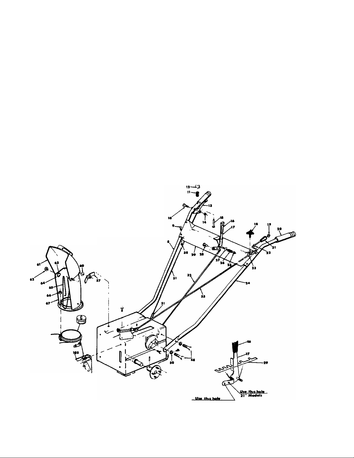
ASSEMBLY INSTRUCTIONS
Right hand (R.H.) and left hand (L.H.) are as observed
from the operating position.
1. Assemble chrome handles {Ref. Ncs. 8 and 24) to
the frame with four hex head cap screws %-16 x %
long and four lock washers DO NOT TIGHTEN.
2. Assemble handle panel (Ref. No. 29) to the handles
with the four carriage bolts ’/i-20x 1V4 Ig. and hex
locknuts %-20 thd. Assemble handle panel so you
can read the instructions on the handle panel from
the operating position. LIFT HANDLE UP AS YOU
TIGHTEN ALL BOLTS AND NUTS ON THE HANDLE
ASSEMBLY.
3. Move the shift lever (Ref. No. 17) on the handle
panel all the way forward into No. 5 position: Use
hole marked "26". Assemble the ferrule to the end
hole in the shift lever from the R.H. side. Screw in
the shifting rod (Ref. No. 32) into the ferrule. Move
the shift lever into the reverse (R) position. Lift the
transmission arm on the rear of the frame all the
way up. Adjust the shift rod by screwing it on or
out until the lower end fits into the transmission
arm. Secure with a cotter pin (Ref. No. 141).
4. CLUTCH GRIP. Place the threaded end of the lock*
out rod (Ref. No. 31) inside the spring. (Opposite
end of the hook.) Screw on the elastic stop not *A-2D
thread approximately to 1 inch. Hook the bent
end of the rod into the eye of the clutch grip from
the right hand side. With the clutch in the released
position, hook the spring into the hole in the link
age arm. The spring and rod should be just tight
enough so the rod is not too loose. Adjust the elastic
stop nut if necessary.
5. Chute Crank. Assemble the chute crank (Ref. No.
33) into the two holes in the handle panel being
sure the rod passes through the lock bracket (Ref.
No. 23). It may be necessary to loosen the black
knob (Ref. No. 18) on the handle panel. Posh the
rod all the way through and assemble it to the uni
versal joint with a cotter pin (Ref. No. 71).
6. Remove the wing nut, washer and carriage bolt
5/16-18 x% Ig. from the chute assembly. Lift the
deflector and reassemble. If the deflector does not
pivot easily loosen the bolt and nut so it pivots free
ly. CAUTION: Release main clutch lever but do not
pry down on lever. Excessive leverage will damage
idler bracket and cause misalignment of idler pul
ley. Belt problems will result.
3« '
Page 3
*?>
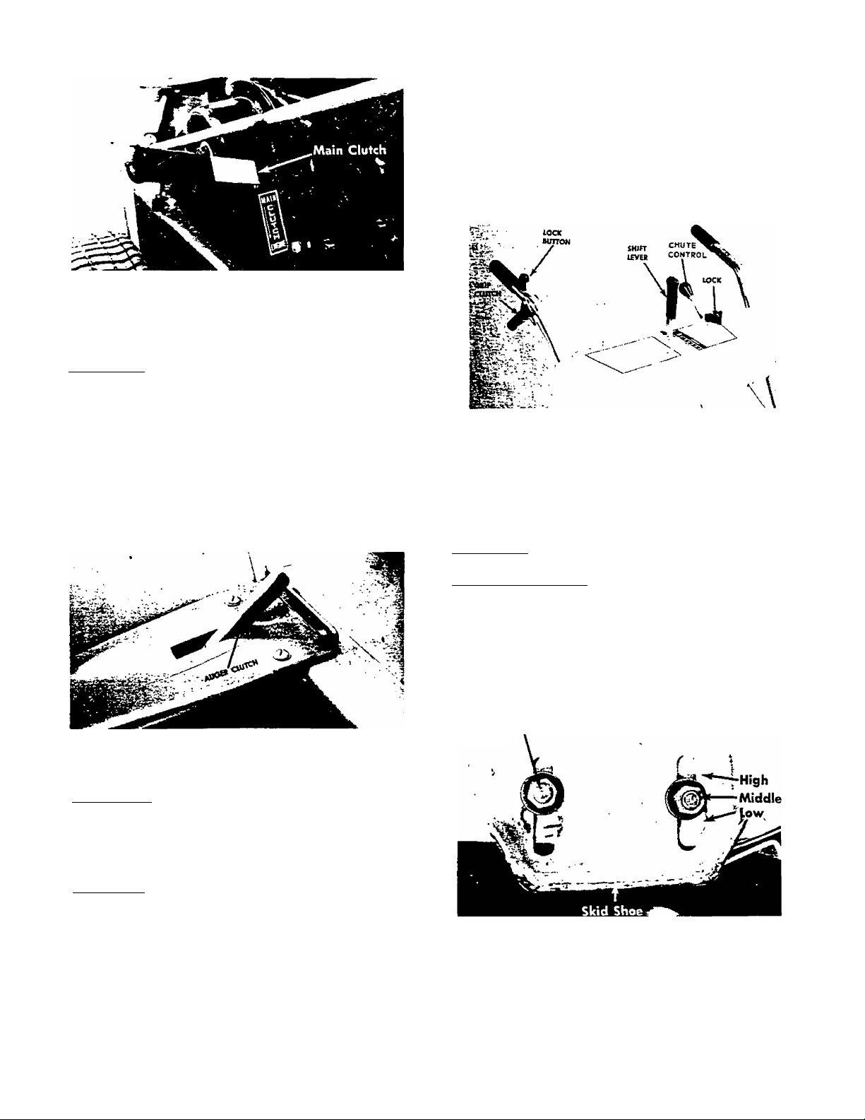
FIGURE 1.
CONTROLS
Auger Clutch is located on the Left Hand side of the
frame just behind the thrower housing, (Shown in the
disengaged position.) When the handle is up, the aug
er is disengaged. WARNING: Engaging auger clutch
with main clutch already engaged will damage pins
on sprocket hob assembly. Damaged pins cause hard
engagement and clutch malfunction. Do not engage or
disengage the auger clutch without first disengaging
the main clutch. Disengaging the auger clutch allows
you to drive the snow thrower to and from the work
area without the auger turning. (See figure 2.)
Shift Lever. The shift lever determines the direction
and speed forward of the drive wheels. Always re
lease the grip clutch when shifting gears. (See figure 3.)
Chute Controls. Release the lock and turn the crank
to rotate the chute. Loosen the wing nut to adjust the
deflector. (See figure 3.)
FIGURE 3.
SKID SHOES
The skid shoes on each side of the thrower are adjust
able by loosening the bolts and nuts.
FIGURE 2.
Main Clutch, This clutch shuts off the power to the
wheels and auger. When the handle is up it is in the
disengaged position. Always shot off the main clutch
when engaging and disengaging the auger dutch.
(Shown in the disengaged position.) (See figure 1.)
Grip Clutch. The grip clutch engages and disengages
the drive wheels. To engage the clutch, squeeze the
handle and depress the button to lock it. Squeezing
the handle again will release it. (Shown in the disen
gaged position.) (See figure 3.)
low Position—Close snow removal.
Middle or High Position—Use when road is uneven.
The skid shoes and shave plate should be replaced
when worn.
The skid shoes may be tipped for better operation.
Bolt and Nut
/
FIGURE 4.
Page 4
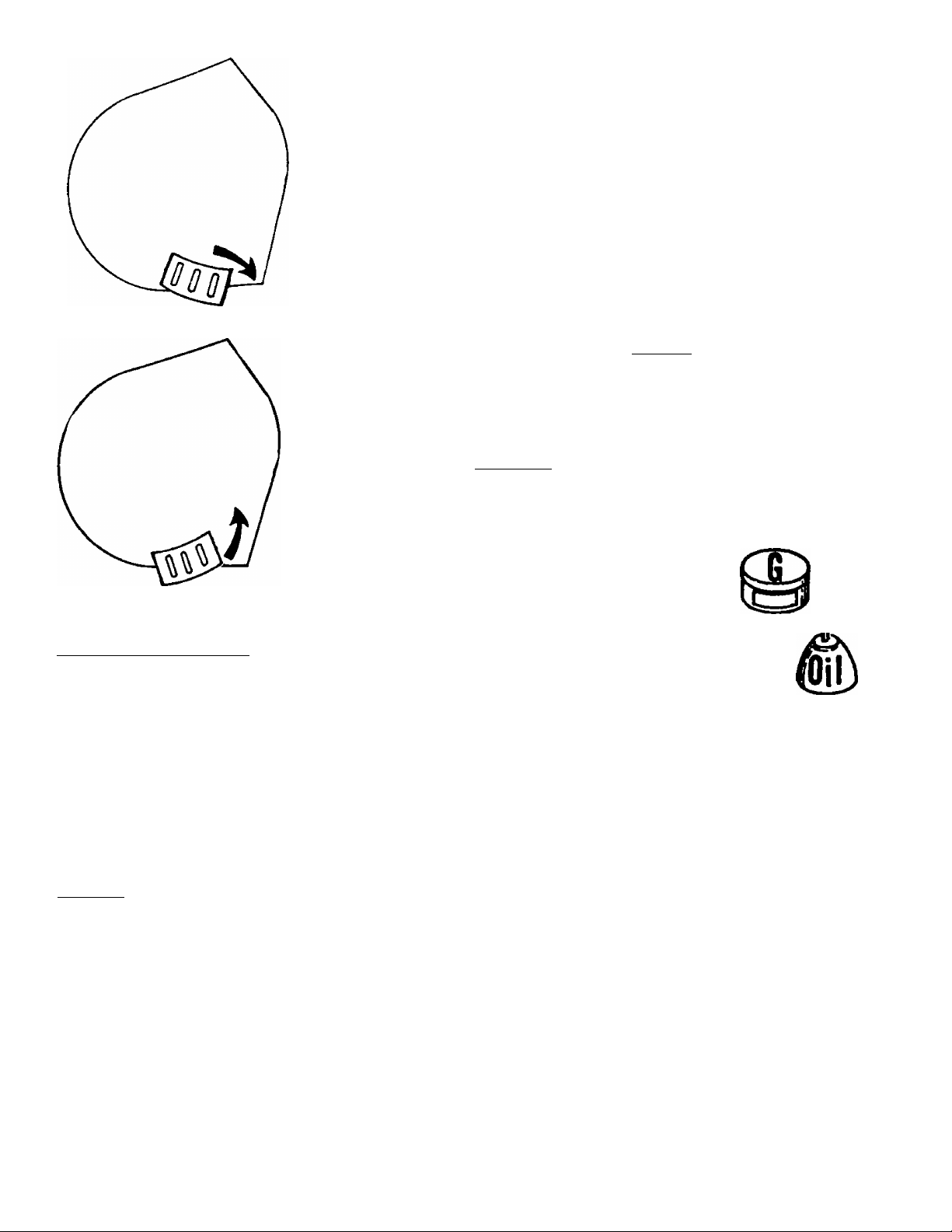
Tip front of skid shoe
down when operat
ing in hard packed
snow.
3. Move the shift lever info number one position. (Use
the stow speeds until you are familiar with the op
eration of your snow thrower.)
4. Squeeze the grip clutch and the snow thrower will
move. Release it and it will stop. Jf
5. Never move the shift lever without releasing the »
grip clutch. The higher the forward position number c
the faster the snow thrower will move over the
ground.
6. NEVER attempt to clean the chute or make any ad
justments while the engine is running.
{ NOTE^
For traction, chains are recommended.
See page 5.
LUBRICATION
Tip front of skid shoe
up when operating in
loose stone or soft
areas.
STARTING YOUR SNOW THROWER
1. Follow your engine instructions for lubrication and
gasoline.
2. Disengage the main clutch (Lever UP).
3. Release the grip clutch and put the shift lever in
neutral position (N).
4. Start the engine in accordance with the engine
manual.
OPERATION
1. With the main dutch disengaged and with the en
gine running at near top speedy engage the auger
dutch. (See figure 2.)
2. SLOWLY engage the main dutch.
Refer to pages 11 and 12. Lubricate after each 25 hours
of operation, the parts indicated. Use multipurpose
automotive grease on parts marked
SAE 30 engine oil on parts marked
NOTE
If repairs or service is needed on the engine
or engine controls such as
the primer, choke or throt
tle control, contact your
nearest authorized engine
service outlet. Check the
'"Yellow Pages" of your
telephone book under "En-
g i nes—Gasol ine".
Fled II F«*l
ImTIw
'Yoitow Pag«*'
and
i-
Page 5

REMOVING THB ORIVE UNIT CONTAINING THE FRICTION DRIVE WHEEL
The dutch bracket must pivot freely and the dutch
linkage must be loose.
1. Remove the frame cover.
2. Remove cotter pins from linkage arm, shifting yoke
rod and shifting rod.
3. Remove the two screws from the pivot bracket as
sembly and lift the bracket up,
4. Remove the three screws holding the dutch
shaft and chain bracket out.
5. Turn and lift out the entire unit from the frame. It
may be necessary to loosen the nut on the dutch
linkage.
6. The unit can now be disassembled on a work
bench.
7. Remove five 3/7" nuts and one elastic stopnut.
8. Remove clutch fork bracket assembly and the
bevel gear housing assembly.
9. Remove three ’4" nuts on the drive wheel shaft
on the bevel pinion.
10. Pull out the clutch shaft.
11. Knock out the drive wheel shaft with a drive pin
from the opposite end of the pinion.
12. Lift out the friction wheel and fork assembly as a
unit.
13. Loosen the three 5/16" screws holding the friction
drive wheel to the friction wheel adapter.
14. Reassemble with new wheel.
NOTE
When reassembling the drive unit the
input chain pinion (Ref. No. 2,16) should
turn freely. If it turns too tightly, loosen
the bearing cap and move the bevel
gear away from the pinion slightly.
NOTE
For more traction, chains are recom
mended.
r
Tire Sizes
13.0x5.00
Chains
394-990A
PNEUMATIC TIRE PRESSURE
The tires are over inflated for
shipping purpose. Tire pressure
should be 7 to 10 psi.
NOTE: If the tire pressure is not
equal in both tires the unit may
pull to one side or the other.
C
Page 6

314-830A
>
V 22
Г.
Page 7

PARTS LIST FOR MODEL 314-830A
REF.
NO.
10
11 736-0169
13 5045
14
15 732-0249 Compression Spring
16 5107
17 713-0127 Chain w/Master Link ^41 x
18 723-0168
19
20
21 736-0264
22 710-0538
23
24
25
26
27
28
29
30
31
32
33
34
35
36
PART
NO.
1
2 712-0158
3
4
5
6 736-0179
7 736-0105
8 9966
9
37
5225
710-0260
712-0107
5223-456
5031
710-0216
5106 Eccenter
5152-456 Chain Guard Brkt. 56
748-0142
712-0107
736-0175
712-0798
736-0169
736-0300
736-0119
712-0267
5451
713-0176
738-0226
715-0118
741-0170
736-0300
710-0347
716-0121
COLOR
CODE
-456
-456
DESCRIPTION
Top Chute Ass'y.
Hex Cent. L-Nut 5/16-18 Thd.
Carriage Bolt 5/16-18x.62"
Lg*
Hex Cent. L-Nut 14-20 Thd. 42 5429-456
Chute Ass'y.
FI-Wash.
Beil-Wash.
Handle Knob Ass'y.
Chute Flange Keeper Ass'y. 46 5000-456 Shave Plate
Hex Scr. %-16x.75" Lg.*
L-Wash. %" Scr.* 1.75" Lg.*
Frame Plate Ass'y.—L.H. 49 5360
Shifting Yoke Ass'y.
40" Lg, 54
Sprocket Idler—10 Tooth
Flange Bearing .500 Dia,
FI-Wash. .33 I.D. X.750 O.D. 58
Hex Scr. w/Lock 5/16-18 x 59
.62" Lg.*
Cent, L-Nut 14-20 Thd.
Wave Wash. 14" Scr.
Hex Nut %-16 Thd.*
L-Wash %" Scr.*
FI-Wash. .39 I.D. x ,78 O.D.
L-Wash. 5/16" Scr.*
Hex Nut 5/16-18 Thd.*
Chain Guard
60 Tooth Sprocket Hub Ass'y.
Spiral Axle
Spirol Pin 5/16 Dia. x 1.75"
Lg.*
Flange Brg.
Fi-Wash. .39 I.D. x % O.D.
Hex Scr. %-16x 1.75" Lg.*
Snap Ring 1.50" Dia.
NEW
PART
N
PART
REF.
NO.
38
39 736-0119
712-0267 Hex Not 5/ 16-18 Thd.*
40
41 5038-456
43
44 5136-456
45 710-0260
47 715-0118
712-0798
50
736-0105
51
52
736-0198
53
710-0389
55
57
715-0118
712-0267 Hex Nut 5/16-18 Thd.*
60
736-0119
61
62
736-0123
63
710-0538
64
712-0287
65
736-0329
66
710-0260
67
736-0119
68
712-0267
69
70
736-0329
71
710-0289
72
73
COLOR
NO.
CODE
5240
L-Wash. 5/16" Scr.*
Thrower Paddle Ass'y.
5115-456 Spacer
Bushing
Carriage Bolt 5/16-18 x.62"
Spring Pin Spiro! 5/16 Dia. x
Bearing Housing Ass'y.
Hex Nut %-16 Thd.*
Belt Wash.
5002-456 Slide Shoe
5136 Bushing
5018-456
5136
5017-456
5136
5139-456
5239-456
FI-Wash. .75 I.D. x 1.25 O.D.
Carriage Bolt %-16 x .75" Lg.*
Spiral Ass'y.—L.H.
Bushing
Spiral Ass'y.—R.H.
Spring Pin Spiral 5/16 Dia. x
L-Wash. 5/16" Scr.*
Bushing
Hex Scr. w/Lock 5/16-18 X
Hex Nut 1/4-20 Thd.*
Carriage Bolt 5/16-18 x.62"
Lg.*
L-Wash 5/16" Scr.*
Hex Nut 5/16-18 Thd.*
Guide Blade
L-Wash. W" Scr.*
Hex Scr. 14-20 X.50" Lg.*
Auger Clutch Cover
DESCRIPTION
Yoke Brkt. Ass'y.
Spiral Hsg. Ass'y.
Lg-
1.75" Lg.
FI-Wash. ,341 I.D.
.62" Lg.
L-Wash. Vi" Scr,*
NEW
PART
N
c
Page 8

314-830A
>
Page 9

PARTS LIST FOR MODEL 314-830A
REF.
NO.
PART
NO.
1
726-0121
732-0145
2
3
4
5
6
7
8
9
10
5132
712-0107
711-0370
720-0142
5131
720-0170
726-0100
1166
11 720-0171
736-0117
12
COLOR
CODE
DESCRIPTION
NEW
PART
Push Cap Va“ Dia.—Black
Compression Spring
Clutch—Grip 39
Hex Cent. L-Nut li-20 Thd.
Clutch Grip Lock Pin
Fl-Bar Grip-Black 42
Shift—Grip
Hand Knob
Push Cap Dia.
Grip-Black 45
Knob
Fl-Wash. 47
13 5121 Chute Crank Lock 48
712-0116
U
732-0193 Compression Spring
15
736-0105
16
711-0179
17
18
19
20
21
22
23
24
25
26
.27
28
29
30
31
32
33
34
5127-456
712-0107 Hex Cent. L-Nut Vi-20 Thd.
747-0113 Lockout Rod
732-0269 Spring
711-0373
5120
712-0116
-456
5228
5061
720-0142 Fi-Bar Grip—Black
732-0185 Tension Spring
5237 7.50" Dia. Pulley-Dr. Plate
712-0375 Hex Cent. L-Nut %-16 Thd.
738-0147
754-0131
756-0137 Fl-ldler 68
710-0224
Hex Stop Nut %-24 Thd. 49
Bell-Wash.
Adj. Ferrule
Panel Assembly
Shifting Rod
Chute Crank
Hex Elastic Nut %-24 Thd.
Belt Guard Ass'y-
Idler Brkt, Ass'y-
Shid. Bolt %-16 Thd.
3V x 35.5 Belt
Hex Seif Tap Scr. #10 x .50"
Lg-*
710-0216 Hex Scr. %-16x.75" Lg.*
35
36
9755-501
Wheel Ass^y.—Comp.
734-0219 Tire—Only (12.5 x 4.50-6)
734-0210 Tube-Only (12.5x4.50-6)
10108
Rim Only
REF.
NO.
37
38
PART
NO.
736-0169
712-0798
COLOR
CODE
L-Wash. % Scr,*
Hex Nut %-16 Thd.*
DESCRIPTION
714-0143 Klik Pin-5/16" Dia, X 1.75" Lg.
40 736-0169
41
5048
L-Wash. Scr.*
Plate Ass'y.
5272 Wheel Hub Ass'y,
43
715-0118
Spring Pin Spiral 5/16 Dia. x
1.75" Lg.
44
46
50
51
52
5076
748-0151
5043
5066
711-0358
5116
711-om
715-0103
5118
Frame Cover
Flange Brg. .75 I.D.
Frame Ass'y.
Joint Brkt. Ass'y.
Joint Block
Chute Brkt. Ass'y.
Cotter Pin 3/32 X 1.00" Lg.*
Roll Pin V4 Dia. x Lg.*
Sprocket Shaft Ass'y.
53 710-0216 Hex Scr. %-16 X .75" Lg.*
54
710-0152
55
712-0287
56 736-0329
57 710-0237
736-0607 L-Wash. 5/16" Scr.*
58
Hex Scr. %-24x 1" Lg.*
Hex Nut li.20 Thd.*
L-Wash. 14" Scr.*
Hex Scr. 5/16-24 X .62" Lg.*
59 710-0442 Hex Scr. 5/16-18 X 1.50" Lg.*
710-0289 Hex Scr. 14-20 x .50" Lg.*
60
61
62
63 714-0128
64 756-0171
65
66
67
69
—
5228-
5230736-0235
736-0169
5124
710-0262
Engine
-456
Belt Guard Ass'y.
Sq. Key 14 X 1" Lg,*
3.50 Dia. Pulley .75 Bore
-456
Top Beit Guard Ass'y.
Fl-Wash.
L-Wash. %" Scr.*
Handle—R.H.
Carriage Bolt 5/16-18 x 1.50"
Lg.*
710-0606 Hex Scr. 14-20 x 1.50" Lg.*
70
71
5123 Handle—L.H.
NEW
PART
C
Page 10

314-830A
10
Page 11

ftEF.
NO.
PART
1
fex 2 711-0404
V.' 3 712-0158
" 4
5 5084
ó 736-0300
7
712-0116
714-Oni
8
9
711-0373
10
714-0111
n
12
714-0129
13
741-0131 Ball Bearing
14
712-0287
NO.
5087
5085
5138
COLOR
CODE
DESCRIPTION
Clutch Linkage
Shid. Nut 5/16-18 Thd.
Hex Cent. L-Nut 5/16-18 Thd.
Pivot Bracket Ass'y.
Linkage Arm
FI-Wash. .39 I.D. x .87 O.D.
Hex Stop Nut %-24 Thd.
Cotter Pin 3/32x 1.00'^ Lg.*
Shifting Rod
Cotter Pin 3/32 X 1.00" Lg.*
Shifting Yoke—Rod
#503 Key %" Dia,
Hex Nut 14-20 Thd.*
15 736-0329 L-Wash. 14" Scr.*
16 5034 Brg. Housing 1.38 Dia.
17
18
711-0360
710-0253
Drive Wheel Shaft
Hex Scr. %-16x 1.00" Lg.*
19 736-0169 L-Wash. %" Scr.*
20
21
22
23 736-0213
24
25
26 741-0919
27
28
29 711-0525
30
31
¿^32
:.V33
'^34 711-0363
35
36
37
38
5082 Chain Brkt. AssV-
712-0375
741-0134
Hex Cent. L-Nut %-16 Thd.
Ball Bearing .25 I.D.
Bell-Wash. .400 I.D. x .88 O.D:
5237
7.50" Dia. Pulley
717-0197 12 Tooth Sprocket
Ball Bearing .87 Dia.
10579
714-0132
Brg. Housing Ass'yHi-Pro Key #605
Drive Shaft
710-0259
736-0197
748-0198
712-0211
Sems Scr. 5/ 16-18 x .62" Lg.*
FI-Wash. .812 I.D.
Spacer
Hex Flange L-Nut %-24 Thd.
Neutral Plate
748-0227
711-0364
748-0227
714-0111
Flange Brg. .62" I.D.
Shift Sleeve
Flange Brg. .62" I.D.
Cotter Pin 3/32" Dia. x
1.00" Lg.* 104
39 5073
40 748-0166
711-0362 Clutch Shaft 106
41
736-0169 L-Wash. .38" Scr.*
42
710-0216
43
741-0131
44
45
736-0192 FI-Wash. .531 I.D. x .94 O.D. 110
46
748-0866
47
712-0200
48
736-0300
49
712-0116
50
732-0157
51
52
736-0119
53
712-0267
54
: 55
56
723-0168
57
713-0155
58
712-0116
59
715-0118
60
"TV
63
64
65
66
67
736-0198
716-0101
714-0137
738-0178
714-0129
748-0852
736-0108
■‘^51
9K62
5034 Brg. Housing 1.38" Dia. 109
5063-
5240
5106
Clutch Fork Ass'y*
Friction Wheel Adapter
Hex Scr. %-16x.75" Lg.* 107
Ball Bearing
Bevel Pinion
Hex Stop Nut 16-20 Thd.
FI-Wash. .39 I.D. x .87 O.D. 113
Hex Stop Nut %-24 Thd.
Spring
-456 Chain Idler Brkt. Ass'y.
L-Wash. 5/16" Scr.* 117
Hex Nut 5/16-18 Thd.* 118
Yoke Brkt. Ass'y.
Eccenter
Sprocket Idler—10 Tooth
#420 Chain x 40.50" Lg.
Hex Stop Nut %-24 Thd.
Spring Pin Spiral 5/16" Dia.
X 1.75" Lg.
Fl-Wash. .765 I.D.
Snap Ring .75" Dia. 126
Hi-Pro Key 3/16x%" Dia. 127
Thrower Axle 128
#503 Key %" Dia.
8-Tooth Sprocket 129
Fl-Wash. .51 I.D. x .75 O.D.
PARTS LIST FOR MODEL 314-830A
HEW
PART
REF.
NO.
68
69
70
71
72
73
74
75
76
77
78
79
80
81
82
83
84
85
86
87
88
89
90
91
92
93
94
95
96
97
98
99
100
101
102
103
105
108
111
112
114
115
116
119
120
121
122
123
124
125
PART
NO.
710-0170 Hex Scr. w/Lock 5/16-24 x
748-0142 Flange Brg. ,50" Dia.
715-0248 Roll Pin 3/16" Dia. X.75" Lg.*
5107 Shifting Yoke Ass'y.
732-0249
735-0114
716-0116
736-0229
5150
717-0151
748-0173
748-0172 Clutch Sleeve
748-0171
5112 Sprocket Hub Ass'y.
748-0151 Flange Brg. .75" I.D.
748-0171 Bronze Bushing
5038-456
748-0171
748-0151 Flange Bearing
736-0123
710-0538 Hex Scr. w/Lock 5/16-18 x
711-0361
748-0227
748-0167
711-0365
5077
748-0852 8-Tooth Sprocket
716-0104
736-0169
712-0711
748-0227 Flange Bearing .62 I.D.
714-0129
714-0126
736-0116
716-0106 "E"-Ring .50" Dia.
717-0288 Wheel Axle Ass'y.
710-0198 Sems Scr. 5/16-18 x.75"
5080
713-0134 #41 Chain w/ Master Link x
5033 Brg. Housing 2" Dia.
741-0133
748-0108 Flange Brg. ,50 I.D.
716-0102
710-0281 Hex Scr. '4-28 x .87" Lg.*
5079
712-0896
736-0119 L-Wash. 5/16" Scr.*
712-0267
732-0157 Spring
747-0113
732-0269
712-0324
5088
712-0116
736-0300 Fl-Wash. .39 I.D, x .87 O.D.
738-0129
748-0108 Flange Brg. .50" I.D.
713-0130 #41 Cham w/Master Link
5075 Clutch Fork Brkt. Ass'y.
748-0151
715-0118
5272
11
COLOR
CODE
DESCRIPTION
.62" Lg.*
Compression Spring
Rubber Bellow
Snap Ring .75" Dia.
Bell-Wash.
Clutch Ass'y,
Clutch Cone
Clutch Housing
Bronze Bushing
Thrower Paddle Ass'y.
Bronze Bushing
Fl-Wash. .341 I.D. x .06 O.D.
.62" Lg.
Bevel Gear Shaft
Flange Brg. .62 I.D.
Bevel Gear
Sleeve
Bevel Gear Housing Ass'y.
"E"-Ring .50" Dia.
L-Wash. -38" Scr.*
Hex Nut H-24 Thd.*
#503 Key .62" Dia.
#606 Hi-Pro Key
Fi-Wash.
Lg-*
Friction Wheel Ass'y.
23" Lg.
Ball Bearing
Snap Ring
Shift Fork
Hex Stop Nut M-28 Thd.*
Hex Nut 5/16-18 Thd.*
Lockout Rod
Spring
Hex Stop Nut '4-20 Thd.
Clutch Brkt.
Hex Stop Nut %-24 Thd.
Axle Bolt .50" Dia.
x 22" Lg.
Flange Brg. .75" I.D.
Spring Pin Spiral 5/16" Dia.
X 1.75" Lg.
Wheel Hob Ass'y.
NEW
PART
Page 12

M
LUBRICATION POINTS
Page 13

LUBRICATION POINTS
Lubricate With a Few Drops of
Light Oil (Ref. Nos. 214, 226,
Lubricate With General Pur
pose Grease (Ref. Nos. 213
and 173).
Uibricat« With a Few Drops
f Ught Oil (Ref. Nos. 204,
;02 and 201).
Lubricate With General Pur>
pose Grease (Ref. No. 197).
13
Page 14

Auger Does Not Operate, Hub
Broken on Sprocket. Roll Pin
Broken.
Defective Engine Pulley or
Misaligned Engine Pulley
Causes Belt Failure.
Do Not Pry Down on Engag
ing Lever. Excessive Leverage
Will Cause Damage to Idler
Bracket. Assembly and Mis
alignment of Idler Pulley. This
Will Result in Belt Damage.
73
O
C
00
If Augers Hits Heads of Bolts
In Housing, Bend Tips of
Auger to Cleor.
This ROLL PIN Referred to as
Shear Pin by Many Users.
Idler Must be in Alignment
With Belt, if Not. Straighten
Idler Bracket to Correct.
Added Spring Pressure Will
Reduce Idler Bracket Assem
bly Vibration and Reduce Belt
Problems. Belt "Slop" Con
Cause Belt to Break.
Chain Must Not Hit Housing
While Operating, If Chain
Hits Flange, File Clearance,
Add Spring Pressure on Idlers
to Reduce "Slap" in Chain.
tn
X
O
O
-H
Z
o
Page 15

ì
Page 16

Remove Frame Cover 5067
to Service Chains.
Unit Will Not Propell With
Damaged Friction Wheel.
Misalignment of Bevel Gear and Pinion Gear
Cause Drag on Chain. Loosen Housing and Re
align,
TROUBLE SHOOTING
Beni Shifting Fork Ccrjse Hard
Shifting of Drive Clutch. Als^
Bent Clutch Fork Assembly.
Also, Bearing Not Pressed
Firmly on Drive Wheel Shaft.
Lockr ^ too Tight on Axle
Bolt ises Drag on Chain.
Do Not Engage Auger With Main Clutch Engaged!
Engaging Auger Clutch With Main Clutch En
gaged Will (tomoge Pins on Sprocket Hub As
sembly. Damaged Pins Cause Hard Auger Clutch
Engagement and Even AUGER CLUTCH FAILURE.
of the "V" Belt to Trap Away From the En-
gitii'Pulley When Main Clutch is Disengaged
Will Also Couse Damoge to Sprockot Hub As
sembly When Auger Clutch is Engogod.
PORM NO. 770-5524
Key Must be Straight in Key
Seat for Correct and Easy
Clutch Operation.
PRINTED IN U.S.A.
 Loading...