

Page 1

10*
Model Nos.
20’’SN0W THROWER
For one year from date of purchase, MTD Products Inc ,
will replace for the original purchaser, free of charge, F.O.B.
factory or authorized service firm, any part or parts found to
be defective in material or workmanship. All transportation
charges on parts submitted for replacement under this war
ranty must be paid by the purchaser. This warranty does not
include replacement of parts which become inoperative
through misuse, excessive use, accident, neglect, improper
maintenance or alterations by unauthorized persons. This
warranty does not include the engine, motor, battery, bat
tery charger or any component parts thereof. For service on
these units refer to the applicable manufacturer's warranty.
The above warranty will apply only to the original owner
and will be effective only if the warranty card has been pro
perly processed. It will not apply where the unit has been
used commercially.
Warranty service is available through your local author
ized service dealer or distributor. UNDER NQ CIRCUM
STANCES WILL THE RETURN OF A COMPLETE UNIT
BE ACCEPTED BY THE FACTORY UNLESS PRIOR
WRITTEN PERMISSION HAS BEEN EXTENDED.
313-205 & 313-230
1.2.Know the controls and how to stop quickly—READ
THE OWNER'S MANUAL.
Disengage power and stop motor before cleaning dis
charge, removing obstacles, making adjustments, or
when leaving operation position.
Never direct discharge at bystanders nor allow anyone
in front of machine—debris may be hidden in the snow.
Keep children and pets a safe distance away.
Do not allow children to operate machine nor allow
adults to operate it without proper instruction.
Adjust height to clear gravel or crushed rock surface.
7. Exercise caution to avoid slipping or falling, especi
when operating in reverse.
Handle gasoline with care — it is highly flammable.
8.
A. Use approved gasoline container^
B. Never add gasoline to a running motor — fill tank
out of doors and wipe up spilled gasoline.
C. Replace gasoline cap securely.
D. Open door if motor is run in garage — exhaust
gases are dangerous.
Disengage all clutches and shift into neutral before
9.
starting motor. Keep hands, feet and clothing away
from power driven parts.
Use a grounded three wire extension cord for all plug
10.
in electric units.
Keep machine in good operating condition and keep
11
safety devices in place.
MTD PRODUCTS INC •
5389 WEST 130th STREET • P. 0. BOX 2741 CLEVELAND OHIO 44111
FORM NO. 770-4790
Page 2
ASSEMBLY INSTRUCTIONS
Right hand (R.H.) and left hand (L.H.) are as observed
from the operating position.
1. Assemble chrome handles (Ref. No. 24 and 29) to
the frame with four hex head cap screws %-16x %
long and four lock washers DO NOT TIGHTEN.
2. Assemble handle panel (Ref. No. 20) to the handles
with the four carriage bolts 14-20 x IVa Ig. and hex
locknuts 14-20 thd. Assemble handle panel so you
can read the instructions on the handle panel from
the operating position. LIFT HANDLE UP AS YOU
TIGHTEN ALL BOLTS AND NUTS ON THE HANDLE
ASSEMBLY.
NOTE: Model 313-205 has no Reverse.
3. The linkage arm (Ref. No. 21) for the transmission is
located on the R.H. side of the frame. Pull the arm
back into reverse. (Towards the operator.) It may be
necessary to roll the snow thrower slightly until it
engages in the reverse position. Assemble the fer
rule to the shift lever handle use hole marked "20"
\ on the handle panel and screw in the shifting rod.
Adjust the rod by screwing it in or out until it fits
into the linkage arm on the side of the frame. Se
cure it with a cotter pin.
4. Chute Crank. Assemble the chute crank (two parts)
into the two holes in the handle panel being sure
the rod passes through the chute control bracket.
Push the rod all the way through and assemble it
to the chute bracket with two cotter pins and flat
washers.
5. Remove the wing nut, washer, and carriage bolt
5/16-18 x% Ig. from the chute assembly. Lift the
deflector and reassemble. If the deflector will not
move, loosen the screw and nut slightly so it pivots
freely.
Use This Hole
20" Models
Use This Hole
26" Models
Page 3
CONTROLS
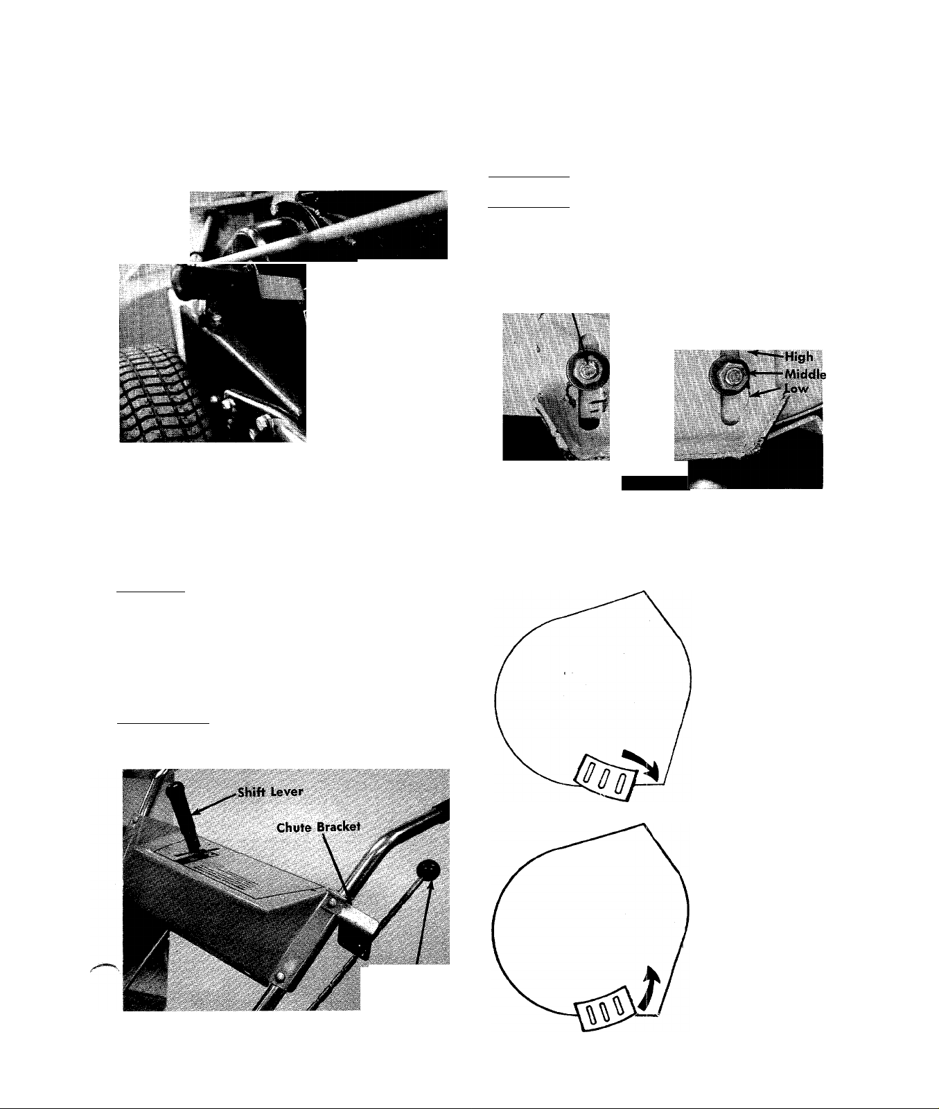
SKID SHOES
/•^MAIN Clutch. This clutch shuts off the power to the
/heels and auger. When the handle is up it is in the
disengaged position. It is shown in the disengaged
position in the photo. (See figure 1.)
.Main Clutch
FIGURE 1
CAUTION
The skid shoes on each side of the thrower are adjust
able by loosening the bolts and nuts.
low Position—Close snow removal.
Middle or High Position—Use when road is uneven.
The skid shoes and shave plate should be replaced
when worn.
Bolt and Nut
Skid Shoe
FIGURE 3.
Main Clutch must be disengaged when
starting.
Shift Lever. Move the shift lever into either forward or
reverse rapidly on model 313-230 only. Engaging
slowly causes wear on the clutch collars. There is no
clutch to engage the drive wheels.
To stop the snow thrower move the shift lever into
neutral (N). Move this control only when the engine is
operating. (See figure 2.)
Chute Controls. Raise the chute control knob and push
or pull to rotate the chute. Loosen the wing nut to
adjust the deflector. (See figure 2.)
The skid shoes may be tipped for better operation.
Tip front of skid shoe
down when operat
ing in hard packed
snow.
FIGURE 2.
Chute Control
Tip front of skid shoe
up when operating in
loose stone or soft
areas.
Page 4

STARTING YOUR SNOW THROWER
1. Follow your engine instructions for lubrication and
gasoline.
2. Disengage the main clutch (Lever UP).
3. Put the shift lever in neutral position (N).
4. Start the engine in accordance with the engine
manual.
OPERATION
1. SLOWLY engage the main clutch.
2. Move the shift lever into FORWARD (F) position.
3. To stop the forward drive of the snow thrower pull
the shift lever into NEUTRAL (N).
NOTE
NOTE
This instruction manual covers various models
and all accessories shown do not necessarily
apply to your model snow thrower.
If repairs or service is needed on the engine
or engine controls such as
the primer, choke or throt
tle control, contact your
nearest authorized engine
service outlet. Check the
"Yellow Pages" of your
telephone book under "Eng i nes—Gasol i ne".
Find It Fait
In Th*
'Yellow Pages'
For more traction, chains are
mended.
Order Model
of Chains
313-205 and 230
393-988
Part No.
recom-
Tire Size
10 X 2.75
LUBRICATION
Refer to the parts drawings. Lubricate after each 25
hours of operation the parts indicated. Use multipur
pose
automotive grease on parts marked
SAE 30 engine oil on parts marked
and
Page 5

Ol
USE THIS HOLE
26"MODEL$
Page 6

Page 7

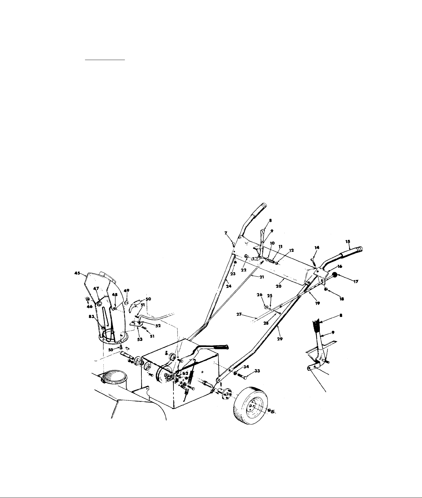
PARTS LIS
SNOW THROWER MODELS 313-205 AND 313-230
REF.
NO.
1
2
3
4
5
6
7
8
9
10
11
12
13 ,
14
15
16
17
18
19
20
21
22
23
24
25
26
27
28
29
32
33
34
PART
NO.
5228
714-105
756-170
5230
736-235
710-262
720-142
5131
736-105
732-193
712-116
5258—435
710- 256
1166
5266—435
722-115
712-107
5269
5125—435
711- 374
711- 179
712- 158
5124
736-147
712-425
5268
710-467
5123
734-468
734-296
734-297
710-216
736-169
COLOR
CODE
DESCRIPTION
Engine
Belt Guard Assembly
Square Key 3/16x3/16x
1" Lg.*
2% Pulley
Top Belt Guard Assembly
Flat Washer
Carriage Bolt 5/16-18 x
1.50" Lg.
Flat Bar End Grip
Shift Grip
Belleville Washer
Compression Spring
Hex Elastic Stop Nut %-24
Thd.
Spirol Housing Assembly
Carriage Bolt 14-20x1’/2"
Lg.*
Grip
Chute Control Bracket
Ball—Knob
Center Lock Nut '/4-20 Thd.
Chute Control Rod
Handle Panel Ass'y.
Shifting Rod
Adjustment Ferrule
Center Lock Nut 5/16-18 Thd
Handle—R.H.
Ext. Lock Washer #10-24
Screw*
Square Nut 10-24 Thd.*
Chute Rod
Truss Hd. Mach. Screw 10-24
X 1" Lg.*
Handle—L.H.
Wheel Assembly Complete
Rim Assembly Only
Tire—Only 10. X 2.75
Hex Hd. Cap Scr. 54-16 x %'
Lg.*
Spring Lock Washer 54" Scr.*
REF.
NO.
35
36
37
38
39
40
41
42
43
44
45
46
47
48
49
50
51
52
53
54
55
56
57
58
59
60
61
62
63
64
65
66
PART
NO.
720-142
5058
710-152
736-169
712-287
736-329
710-237
736-119
710-442
710-289
5225—435
712-158
736-179
710-260
736-105
5140-
714-111
736-300
5265732-211
710- 289
714- 126
711- 519
741-162
754-133
712- 1 16
756-137
738-147
732-185
712-375
748-151'
715- 107
COLOR
CODE
-435
-435
DESCRIPTION
Flat Bar End Grip
Idler Bracket Assembly
Hex Hd. Cap Scr, %-24 x 1"
Lg.*
Spring Lock Washer %" Scr.*
Hex Nut '/4-20 Thd.*
Spring Lock Washer Va" Scr.*
Hex Hd. Cap Screw 5/16-24
%" Lg.*
Spring Lock Washer 5/16"
Screw*
Hex Hd. Cap Screw 5/16-18
X l'/2" Lg.*
Hex Hd. Cap Screw 'A-20 x
'/2" Lg.*
Top Chute Assembly
Hex Center Lock Nut 5/16-
18 Thd.
Flat Washer
Carriage Bolt 5/16-18 x%"
Lg.*
Belleville Washer
Chute Wing Assembly
Cotter Pin 3/32 Dia. x 1"
Lg.*
Flat Washer .406 i.D. x .734
O.D.
Chute Bracket
Chute Guard
Hex Hd, Cap Scr. 'A-20 x '/2"
Lg.*
Hi Pro Key #606
Drive Shaft
Ball Bearing
3 V-Belt 31.5
Hex Elastic Stop Nut %-24
Thd.
Flat Idler
Shoulder Bolt %-16 Thd.*
Tension Spring
Hex Center Lock Nut %-16
Thd.*
Flange Bearing %" Dia.
Spirol Pin
REF.
NO.
68
69
70
71
72
73
74
75
76
77
78
79
80
81
82
83
84
85
86
87
88
89
90
91
92
93
94
95
96
97
98
99
PART
NO.
710-224
5051
5041
710-289
736-264
741-133
5245
736-192
756-136
710-555
5244
736-119
712-267
5031-
712-107
712-107
5156
736-192
741-133
5267736-329
710-289
710-538
736-264
712- 267
736-119
710-606
710-152
736-169
6605-
713- 106
5251-
COLOR
CODE
-435
-435
-435
-435
DESCRIPTION
Sems Hex Hd. Self Tap Scr.
Type A #10-32x'/2" Lg.
Gear—Housing Assembly
Frame Assembly
Hex Hd. Cap Scr. Vi-20 x
'/2" Lg.*
Flat Washer 5/16 Scr.*
Ball Bearing '/2" I.D.
Bearing Housing Assembly
Flat Washer
5" Dia. Pulley with Sprocket
Pilot Scr. %-16 x .88" Lg.
Housing
Spring Lock Washer 5/16" Scr.
Hex Nut 5/16-18 Thd.*
Chute Flange Keeper Ass'y.
Hex Center Lock Nut 'A-20
Thd.
Hex Center Lock Nut '/i-20
Thd.
10 Tooth Sprocket
Flat Washer .530 I.D. x .930
O.D.
Ball Bearing '/2" I.D. x 1%
O.D.
Chain Guard
Spring Lock Washer Scr.*
Hex Hd. Cap Screw 'A-20 x
'/2" Lg.*
Hex Hd. Cap Screw with
Lock 5/16-18 X .62" Lg.
Flat Washer
Hex Nut 5/16-18 Thd.*
Spring Lock Washer 5/16
Screw*
Hex Hd. Cap Screw 'A-20 x
l'/2" Lg.*
Hex Hd. Cap Screw %-24 x
V' Lg.*
Spring Lock Washer %Scr.*
Chain Adjuster
Roller Chain #41 x31.5 Lg.
without Master Link
Spiral Assembly
Page 8

o
70
z
p
VI
V|
0
'O
O
z
-H
PARTS LIST FOR SNOW THROWER MODELS 313-205 AND 313-230
REF.
NO.
100 748-110
1
101 710-260
PART
NO.
COLOR
CODE
DESCRIPTION
Flange Bearing % I.D. 129 711-355 Shaft
Carriage Bolt 5/16-18 x%" 130
Lg.*
102
710-260
Carriage Bolt 5/16-18 x%"
Lg.*
103
736-119
Spring Lock Washer 5/16"
Scr.*
104
105
106
712-267
5001—435
710-389
Hex Nut 5/16-18 Thd.*
Shave Plate
Carriage Bolt %-16x%"
Lg.*
107
108 736-105
109
no 710-152
5002—435
712-798
Slide Shoe
Belleville Washer
Hex Nut %-16 Thd.*
Hex Hd. Cap Screw %-24 x
1" Lg.*
111
112
113
114
115
116
736-169
711-520
726-100
5057
5051
710-259
Spring L-Wash. %" Scr.*
Spiral Axle
Push Nut % Rod Pal Nut
Rod
Gear Housing Assembly
Sems Hex Hd. Cap Scr. 5/16-
18 X %" Lg.*
117
118
119
120
121
714-111
5053
738-140
5054
710-259
Cotter Pin 3/32 X 1" Lg.*
Shifting Bracket
Shoulder Bolt 5/16-18 Thd.
Shifting Yoke
Sems Hex Hd. Cap Screw
5/16-18 x%" Lg.*
122
712-429
Hex Elastic Stop Nut 5/16-
18 Thd.
123
124
125
126
127
748-227
711-354
715-114
5137
713-129
Flange Bearing % Dia.
Shifting Shaft
Spirol Pin '/4" Dia. X 1" Lg.*
Spacer Hub Assembly
Roller Chain with Master
Link #41 X 24" Lg.
128
716-106
"E"—Ring Truarc #5133-62
%" Dia.*
REF.
NO.
PART
NO.
COLOR
CODE
DESCRIPTION
736-116 Flat Washer .625 I.D. x .937
O.D.
131 713-131 Roller Chain with Master Link
#41 X 17" Lg.
132
133
5093
715-114
134 748-164
Shaft Assembly
Spirol Pin 14" Dia. X 1.50" Lg.*
10 Teeth Spur Gear
135 748-161 Clutch Collar
136
716-106 "E"—Ring Truarc #5133-
62 %" Dia.*
137
748-162
62 Teeth Spur Gear
(313-230 Only)
138
714-137
Key 3/16 Thick x%" Dia.
1.062
139 748-163
21 Teeth Spur Gear
(313-230 Only)
140 736-116
Flat Washer .625 I.D.x .937
O.D.
141
716-106
"E"—Ring Truarc #5133-62
%" Dia.*
142
143 716-104
5090 Wheel Axle Assembly
"E"—Ring Truarc #5133-50
’/2" Dia.*
144 748-852
145
713-131 Roller Chain with Master Link
8 Tooth Sprocket
#41 X 17" Lg.
146
147
148 736-119
714-129
5051
Woodruff Key #503
Gear Housing Assembly
Spring Lockwasher 5/16"
Screw*
149 712-267
150 714-126
151
152
710-322
713-723 Master Link for #41 Chain
Hex Nut 5/16-18 Thd.*
Hi Pro Key #606 (313-230 Onl
Hex Sem.s Scr. 5/16-18 x 1.00"
(Use with Ref. No. 98)
153
154
155
156 -
5049
5223
5055
±726-111
-------------
Gear Hsg. Half Ass'y.
Chute Ass'y.
Frame Cover
-L Push Ca D . 188 Rod
----------------
Lg.
(/»
*For faster service obtain standard nuts, bolts, and washers locally. If these items cannot be obtained locally,
order by part number and size as shown on parts list.
 Loading...