

Page 1
OWWirS GUIDE
• ASSEMBLY • OPERATION • MAINTENANCE • PARTS •
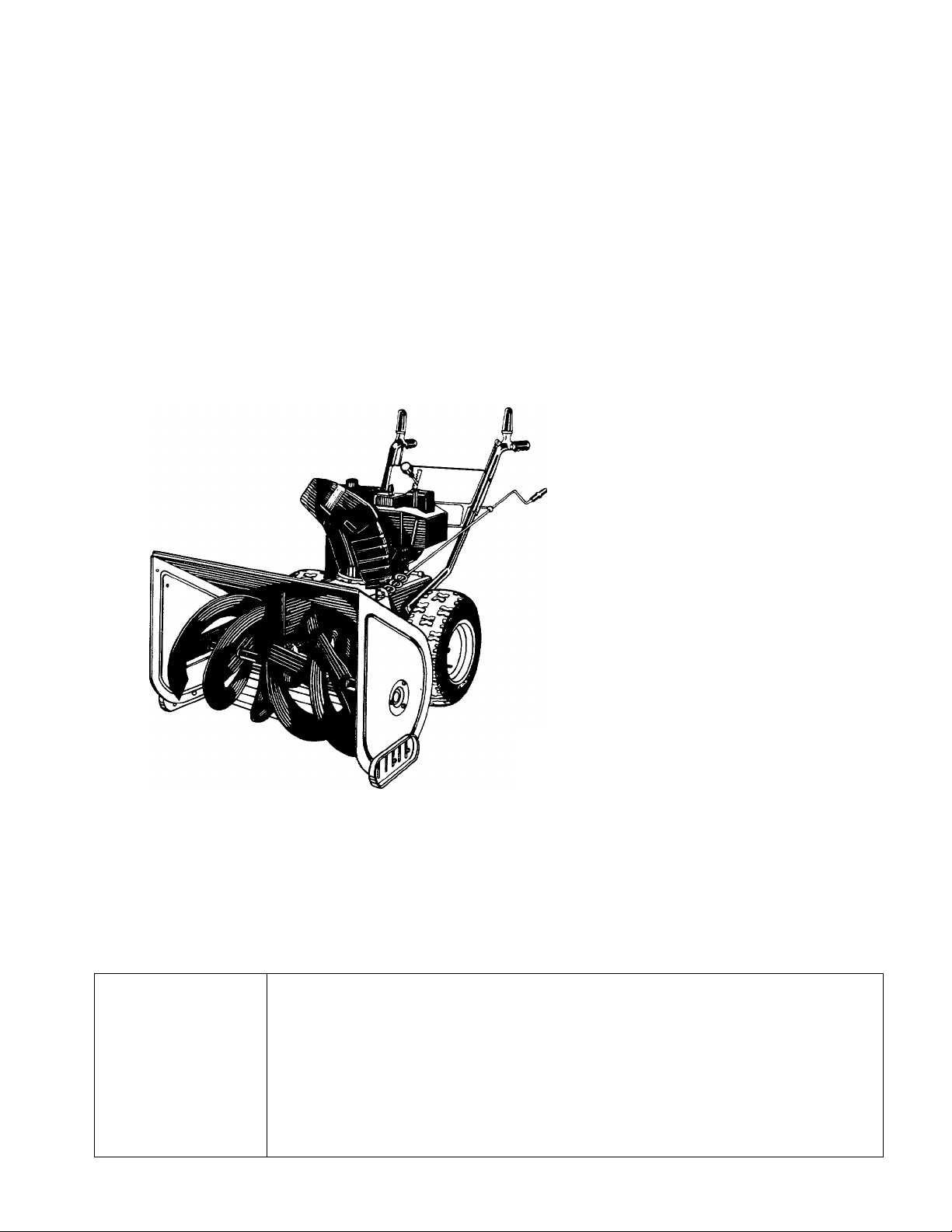
33" SNOW
THROWER
$1.00
Model Number
312-980I000
IMPORTANT!
Record the Model No. and Mfg. Code which
appear on your unit in the space below. You
must have these numbers, along with the date
of purchase, in order to receive warranty or ser
vice.
MEETS ANSI SAFETY STANDARDS
MODEL NO. MFG. CODE
Important:
Made ^
in
AMERICA
Read Safety Rules and Instructions Carefully
FORM NO. 770-5901G
Page 2

IMPORTANT
THIS SYMBOL POINTS OUT IMPORTANT SAFETY I^STRUCTIONS WHICH, IF NOT FOLLOWED, COULD ENDANGER THE PERSONAL
SAFETY AND/OR PROPERTY OF YOURSELF AND CTHERS. READ AND FOLLOW ALL INSTRUCTIONS IN THIS MANUAL BEFORE
A
AHEMPTING TO OPERATE YOUR SNOWTHROWEIL FAILURE TO COMPLY WITH THESE INSTRUCTIONS MAY RESULT IN PER
SONAL INJURY. WHEN YOU SEE THIS SYMBOL— A HEED ITS WARNING.
Your snow thrower was t uilt to be operated according to the rules for safe operation in this manual.
DANGER; As with any type of power equipment, careiessness or error on the part of the operator can result in
A
serious injury. If you violi ite any of these rules, you may cause serious injury to yourself or others.
SAFE OPERATION PRACTICES
A
A'
TRAINING
A
A
A
1. Read this owner’s guide carefully. Be thorc ughly famil
2. Never allow children to operate equipment. Never allow
3. No one should operate this unit while in oxicated or
4. Keep the area of operation clear of all peisons, espe
5. Exercise caution to avoid slipping or fallinn, especially
PREPARATION
1. Thoroughly inspect the area where the eqt ipment is to
2. Disengage all clutches and shift into ne Jtral before
3. Do not operate equipment without wearing adequate
4. Check the fuel before starting the engine. Gasoline is
5. Use a grounded three wire plug-in for all un ts with elec
6. Adjust collector housing height to clear gravel or
7. Never attempt to make any adjustments wh He engine is
8. Let engine and machine adjust to outdoor :emperature
9. Always wear safety glasses or eye shields Juring oper
OPERATION
1. Do not put hands or feet near rotating parts. Keep clear
2. Exercise extreme caution when operating in or cross
3. After striking a foreign object, stop the enc ine, remove
4. If the snow thrower should start to vibrate abnormally,
iar with the controls and proper use of the equipment.
Know how to stop the unit and disengage the controls
quickly.
adults to operate equipment without proper nstructions.
while taking medication that impairs the senses or reac
tions.
cially small children and pets.
when operating in reverse.
be used and remove all door mats, sleds, bDards, wires
and other foreign objects.
starting engine.
winter outer garments. Wear footwear which will
improve footing on slippery surfaces.
an extremely flammable fuel. Do not fill tie gasoline
tank indoors, while the engine is running, or while the
engine is still hot. Replace gasoline cap securely and
wipe off any spilled gasoline before startinci the engine
as it may cause a fire or explosion.
tric drive motors or electric starting motors.
crushed rock surface.
running (except where specifically recorr mended by
manufacturer).
before starting to clear snow.
ation or while performing an adjustment or repair, to
protect eyes from foreign objects that ma r be thrown
from the machine in any direction.
of discharge opening at all times.
ing gravel drives, walks, or roads. Stay ale 1 for hidden
hazards or traffic. Do not carry passengers.
wire from spark plug, and thoroughly inspect the snow
thrower for any damage. Repair the damage before
restarting and operating the snow thrower.
stop the engine and check immediately fo ■ the cause.
Vibration is generally a warning of trouble.
5. Stop engine whenever you leave the operating position,
before unclogging the collector/impeller housing or dis
charge guide, and making any repairs, adjustments, or
inspections.
6. Take all possible precautions when leaving the unit
unattended. Disengage the collector/impeller, shift into
neutral, stop the engine, and remove the key.
7. When cleaning, repairing, or inspecting, make certain
collector/impeller and all moving parts have stopped.
Disconnect spark plug wire and keep away from plug to
prevent accidental starting.
8. Do not run engine indoors, except when starting engine
and transporting snow thrower in or out of building.
Open doors. Exhaust fumes are dangerous.
9. Do not clear snow across the face of slopes. Exercise
extreme caution when changing direction on slopes. Do
not attempt to clear steep slopes.
10. Never operate snow thrower without guards, plates, or
other safety protection devices in place.
11. Never operate snow thrower near glass enclosure,
automobiles, window wells, drop off, etc., without prop
er adjustments of snow thrower discharge angle. Keep
children and pets away.
12. Do not overload machine capacity by attempting to
clear snow at too fast a rate.
13. Never operate the machine at high transport speeds on
slippery surfaces. Look behind and use care when
backing.
14. Never direct discharge at bystanders or allow anyone in
front of unit.
15. Disengage power to collector/impeller when transport
ing or not in use.
16. Use only attachments and accessories approved by the
manufacturer of snow thrower (such as wheel weights,
counter weights, cabs, etc.).
17. Never operate the snow thrower without good visibility
or light. Always be sure of your footing and keep a firm
hold on the handles. Walk, never run.
MAINTENANCE AND STORAGE
1. Check shear bolts, engine mounting bolts, etc., at fre
A
quent intervals for proper tightness to be sure equip
ment is in safe working condition.
2. Never store the machine with fuel in the fuel tank inside
a building where ignition sources are present, such as
hot water and space heaters, clothes dryers, and the
like. Allow engine to cool before storing in any enclo
sure.
3. Always refer to owner’s guide instructions for important
details if snow thrower is to be stored for an extended
period.
4. Run machine a few minutes after throwing snow to pre
vent freeze up of collector/impeller.
Page 3
ASSEMBLY
NOTE: This unit is shipped WITHOUT GAS-
OLiNE or OIL After assembly, see separate engine
manual for proper fuel and engine oil recommenda
tions.
Lockout Rod
Chute Crank Assembly
FIGURE 1.
Y
--------
^
FIGURE 2.
Tools Required for Assembly:
Screwdriver
9/16” Wrench
1/2” Wrench
7/16” Wrench
3/8” Wrench
or One Adjustable Wrench
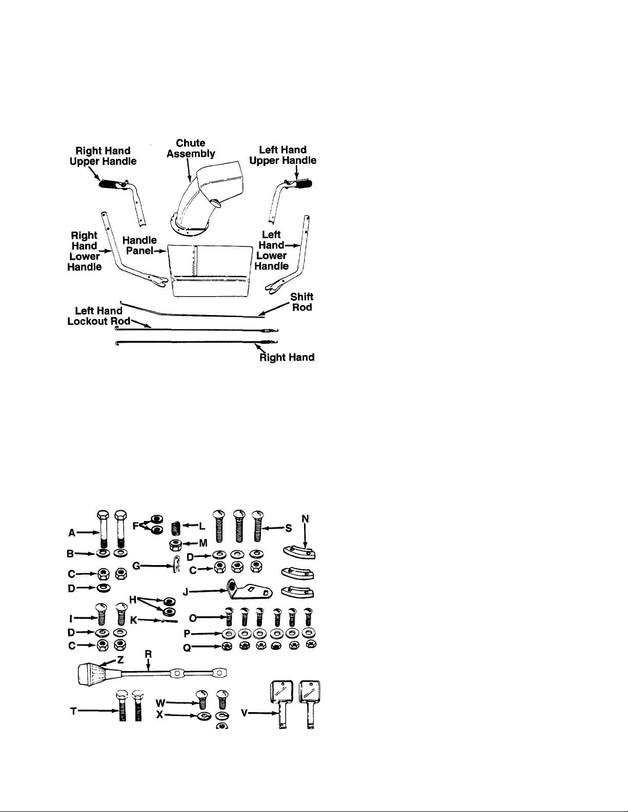
Loose Parts in Carton (see figure 1):
(1) Upper Handle Assembly—L.H.
(1) Lower Handle—L.H.
(1) Upper Handle Assembly—R.H.
(1) Lower Handle—R.H.
(1) Handle Panel
(1) Chute Assembly
“(1) Parts taped together which include;
(1) Right Hand Lockout Rod
(1) Left Hand Lockout Rod
(1) Shift Rod
(1) Chute Crank Assembly
Contents of Hardware Pack (see figure 2):
(Hardware pack may contain extra items which are
not used on your unit.)
A (2) Hex Bolts 3/8-16x2” Long
B (2) Belleville Washers 3/8” I.D.
C (7) Hex Nuts 5/16-18 Thread
D (6) Belleville Washers 5/16” I.D.
F (2) Flat Washers 5/16” I.D.
G (1) Hairpin Clip
H (2) Flat Washers 3/8” I.D. X 5/8” O.D.
I (2) Carriage Bolts 5/16-18 X 3/4” Long
J (1) Chute Crank Bracket
K (1) Cotter Pin
L (1) Compression Spring
M (1) Hex Insert Lock Nut 5/16-18 Thread
N (3) Chute Flange Keepers
O (6) Truss Machine Screws 1/4-20 x 3/4” Long
P (6) Flat Washers 1/4” I.D.
Q (6) Hex Lock Nuts 1/4-20 Thread
“R (1) Shift Lever
S (3) Carriage Bolts 5/16-18 x 2” Long
T (2) Hex Bolts 5/16-18x13/4” Long*
U (2) Hex Insert Lock Nuts 5/16-18 Thread*
V (2) Ignition Keys (May be Attached to Engine)
W (2) Carriage Bolts 5/16-18 X 5/8” Longt
X (2) Lock Washers 5/16” I.D.t
Y (2) Hex Nuts 5/16-18 Threadt
Z (1) Shift Knob
tOptional Parts
*The augers are secured to the spiral shaft with two
hex bolts and hex insert lock nuts (see ref. nos. 40
and 50 on page 22). If you hit a foreign object or ice
jam, the snow thrower is designed so that the hex
bolts will shear. Two replacement hex bolts and nuts
are provided in the hardware pack for your conve
nience. Store in a safe place until needed.
Page 4
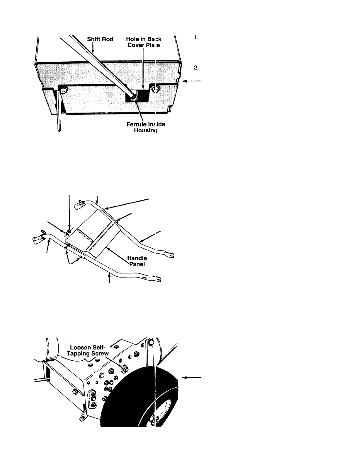
FIGURE 3.
Remove snow thrower and all parts from the car
ton. Check all carton inserts to be certain that all
loose parts and literature have been removed
before the carton is discarded.
Attach the shift rod to the shifting mechanism,
located inside the snow thrower frame, as follows.
■See figure 3.
a. Place the threaded end of shift rod into the
hole in the back cover.
b. Thread the shift rod into the ferrule which is
attached to the shifting mechanism until the
ferrule is approximately halfway down the
threaded end of the rod. Adjustment of shift
rod will be made in step 17.
NOTE: The shift mechanism is a movabie assembly.
It may be helpful to pull the linkage (and ferrule) clos
er to the opening in the back cover when assembling
the shift rod.
Hex Nut
Belleville
Washer (D)
Right
Hand
Upper
Handle
FIGURE 4.
(C)
Carriage
Bolt (S)
Left Hand
Upper Handle
Right Hand
Lower Handle
Carriage
Bolts (S)
Leave Open
Left I-land
Lower Handle
Preassemble the handles to the handle panel as
follows. See figure 4.
a. Place two carriage bolts (S) through the right
hand upper and lower handles (both carriage
bolts go through both handles).
Attach right hand handles to handle panel by
b.
placing carriage bolts through the holes in the
handle panel.
Secure with two belleville washers (D) (cupped
c.
side of washer against the handle panel) and
hex nuts (C). Do not tighten at this time.
Attach the left hand upper and lower handles
-d.
in the same manner, using only one carriage
bolt, belleville washer and hex nut in the upper
hole on the handle panel. Leave bottom hole
open.
FIGURE 5.
4. To attach the handle assembly to the unit, loosen
one self-tapping screw and belleville washer on
each side of the unit. See figure 5. A 9/16”
wrench or adjustable wrench is required.
Page 5
Hex Bolt (A)
Belleville
Washer (B)
FIGURE 6.
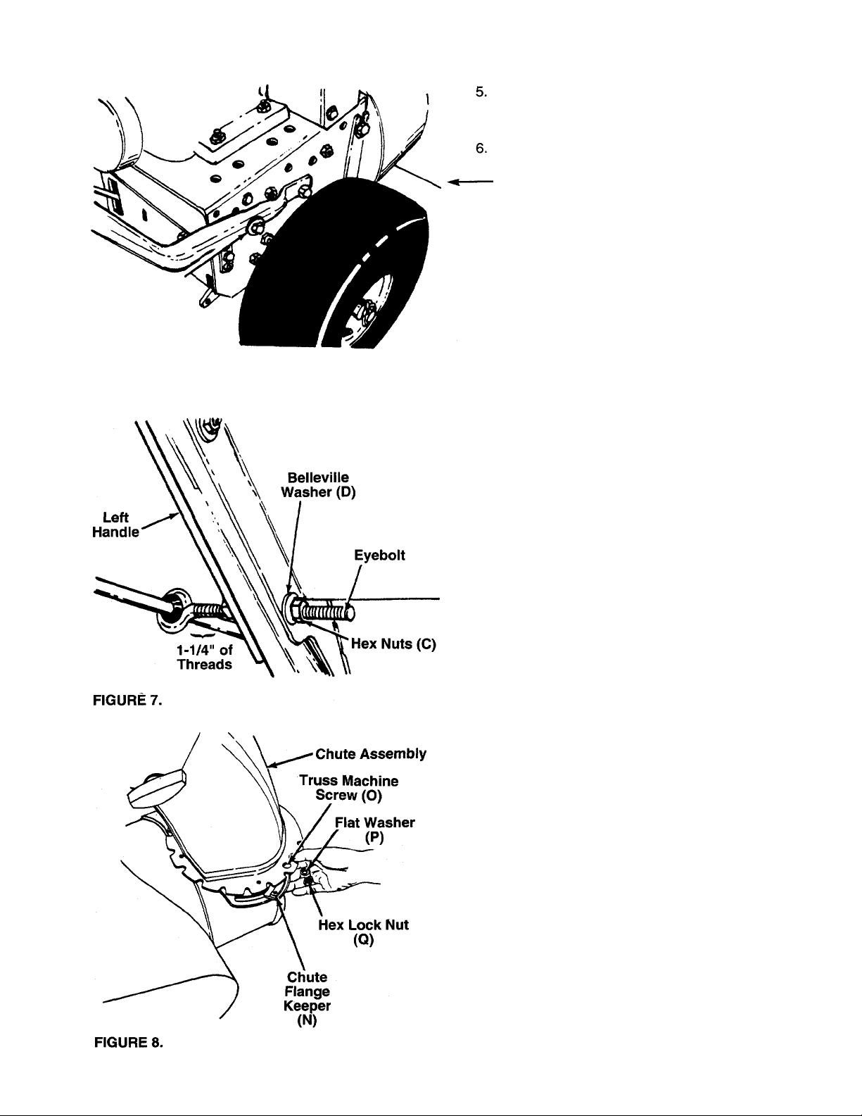
Slide the slotted end of the handles under the
belleville washers on the self-tapping screws
which were loosened in step 4.
Secure the upper hole in the handles with belle
ville washers (B) (cupped side against the han
dles) and hex bolts (A). See figure 6. Do not tight
en at this time.
7. Thread one hex nut (C) onto the eyebolt on the
chute crank assembly until there is approximately
1-1/4" of threads showing between the nut and
—the head of the eyebolt. See figure 7.
8. Place the eyebolt into the lower hole in the left
handle and handle panel. See figure 7. Secure
with belleville washer (D) (cupped side against
the handle panel) and hex nut (C). Do not tighten
until after attaching the other end of the chute
crank (step 14).
9. Tighten securely all bolts and nuts on the handle
panel and all four bolts which secure the handles
to the frame.
10. Grease the chute opening using a multi-purpose
automotive grease or equivalent.
11. Place chute assembly over chute opening, with
the opening in the chute assembly facing the front
of the unit. Place chute flange keepers (N)
beneath lip of chute assembly. Secure with truss
machine screws (O), flat washers (P) and hex
-------
lock nuts (Q) as shown in figure 8. Tighten with a
7/16" wrench, then back off 1/4 turn to allow
easier movement.
Page 6
Flat
Washers
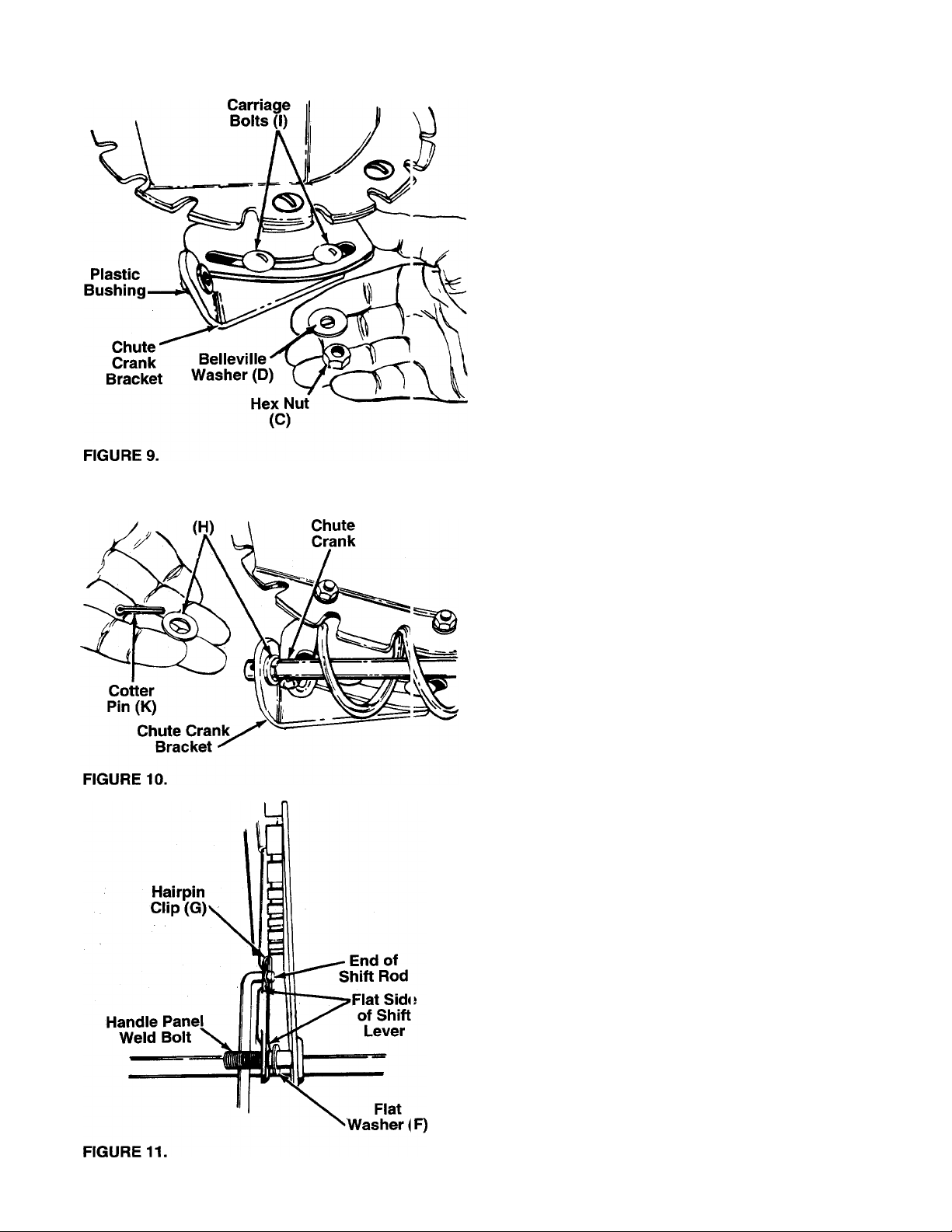
Attach chute crank bracket to the extension on
12.
the left side of the chute opening (bracket goes
beneath the extension) as shown in figure 9.
Secure with carriage bolts (I), belleville washers
(D) (cupped side of washers goes against the
bracket) and hex nuts (C). Tighten finger tight
only at this time.
13. Place one flat washer (H) on the end of the chute
crank, then insert the end of the crank into the
hole in the plastic bushing in the chute crank
------
bracket. See figure 10. Place the other flat wash
er (H) on the end of the chute crank, and insert
cotter pin (K) into hole in the end of crank. Secure
by bending the ends of cotter pin in opposite
directions.
14. Adjust the chute bracket so that the spiral on the
chute crank fully engages the teeth on the chute
assembly. Tighten the nuts on the chute crank
bracket securely. Tighten the hex nuts on the
eyebolt at the handle panel.
15. Thread shift knob (Z) onto the shift lever (R).
16. Place one flat washer (F) over the weld bolt on
the handle panel. Place shift lever (R) through
slot in handle panel, with the flat side of shift lever
against bracket on handle panel. Place the hole
in the end of the shift lever over the handle panel
------
weld bolt. See figure 11.
17. Place the shift lever in the fastest forward position
(5th speed). Push the shift rod all the way forward
(assembled to the ferrule in step 3). Thread the
shift rod in or out of the ferrule as necessary until
the end of the rod lines up with the hole in the
shift lever. Insert end of rod into hole in shift lever
and secure with hairpin clip (G). See figure 11.
Page 7
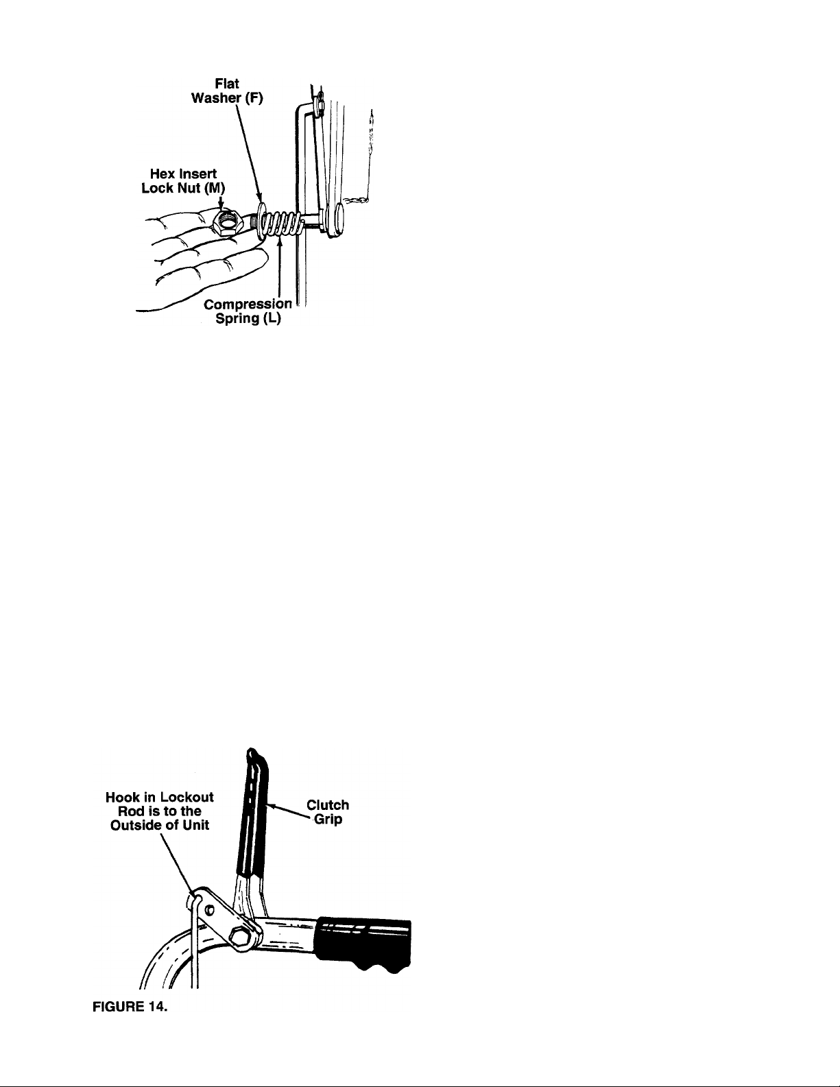
FIGURE 12.
18. Secure with flat washer (F), compression spring
--------(L) and hex insert lock nut (M). See figure 12.
Tighten lock nut until compression spring returns
the shift lever into detent slots on handle panel.
NOTE: The adjustment of the shift rod must be
checked as described in step 23 before the unit is
operated.
Left Hand
Lockout
Rod
1-1/2"
Thread
FIGURE 13.
' Right Hand
Lockout
Rod
} 1/4” of
Thread
19. There is a left and a right hand lockout rod. The
left hand lockout rod is label “L”.
Approximate initial settings for the lockout rods
are as follows: The left hand lockout rod for the
drive clutch should have approximately 1-1/2
inches of thread showing below the nut. The right
hand lockout rod for the auger clutch should have
approximately 1/4 inch of thread showing below
------
the nut. See figure 13.
FINAL ADJUSTMENT MUST BE MADE AS
DESCRIBED IN STEPS 21 AND 22. If the left
hand lockout rod is not adjusted correctly, the
shift lever cannot be shifted past neutral. If the
right hand lockout rod is not adjusted correctly,
the augers will not stop rotating.
20. Hook the right hand lockout rod into the top hole
provided in the right hand clutch grip (auger
-------clutch). See figure 14. Hook the left hand lockout
rod (labeled “L”) into the top hole in the left hand
clutch grip (drive clutch). The hook is to the out
side of the unit.
Page 8
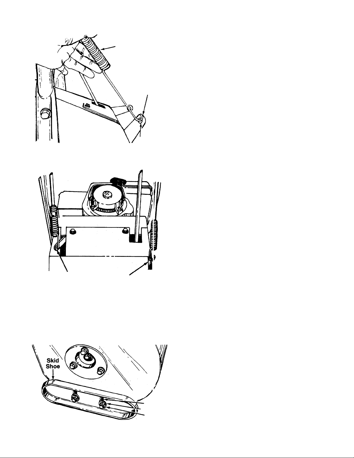
FIGURE 15.
Drive
Bracket
FIGURE 16.
FIGURE 17.
Left Hand
Lockout Rod
Drive Brncket
Auger <
Bracket
Hook i ri
Sprint I
Hole: n
Hich
Middle
Low
21. Swing the left hand lockout rod down and simply
hold it beside the drive bracket. Do not pull on
spring. Do not move bracket. The hook on the
end of the spring must line up with the center of
the hole in the drive bracket. See figure 15.
If it does not, adjust the nut on the lockout rod by
sliding the spring up and using a 7/16” wrench to
move the nut on the end of the rod up or down as
necessary until the hook on the spring aligns with
the center of the hole in the bracket as shown in
-------
figure 15.
Hook spring into drive bracket. See figure 16.
22. Adjust the right hand lockout rod in the same
manner as the left hand lockout rod. Refer to
Step 21. When adjustment is correct, hook the
-------
spring into the auger bracket. See figure 16.
WARNING: There must not be any ten
sion on either clutch rod spring with the
A
drive or auger clutch grip in the disen
gaged (up) position. These clutches are a
safety feature, and their function can be
overridden if there is tension on either
spring with the clutches disengaged.
23. Check for correct adjustment of the shift rod as
follows.
a. Disconnect and ground the spark plug wire
against the engine.
b. Place the shift lever in the neutral position.
Push the unit back and forth. It should move
freely.
c. Engage the drive clutch grip (located on the
left handle) by squeezing the clutch grip
against the handle. Push the unit back and
forth. It should still move freely. If the wheels
tend to lock up, adjustment is necessary.
To adjust the shift lever, place the shift lever in the
fastest forward position (5th speed). Remove the hair
pin clip which secures the shift rod to the shift lever
(refer to figure 11), and remove the rod from the lever.
Push the shift rod all the way forward. Thread the shift
rod in or out of the ferrule one or two turns as neces
sary, until the end of the rod lines up with the hole in
the shift lever. Insert end of rod into hole in shift lever
and secure with hairpin clip. Recheck the adjustment.
24. The space between the shave plate and the
ground can be adjusted. For close snow removal,
place skid shoes in the low position. Use middle
or high position when area to be cleared is
-------
uneven. See figure 17.
Adjust skid shoes by loosening the four hex nuts
and carriage bolts and moving skid shoes to
desired position. Make certain the entire bottom
surface of skid shoe is against the ground to
avoid uneven wear on the skid shoes. Retighten
nuts and bolts securely.
Page 9
Ridge
FIGURE 18.
OPTIONAL EQUIPMENT
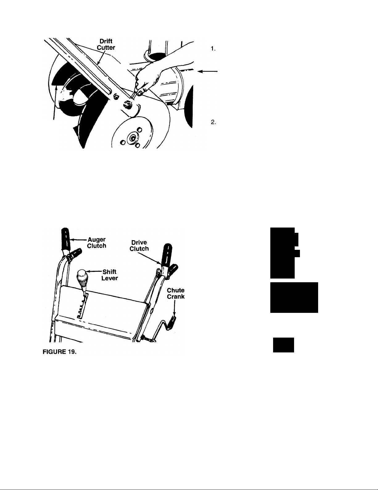
If your unit is equipped with optional drift cutters,
use a 1/2" wrench to remove the carriage bolts,
lock washers and hex nuts holding the drift cut
ters to the auger housing. See figure 18. Turn
and place the drift cutters in position (ridges on
drift cutters go toward the outside of the unit).
Secure with the hardware just removed, carriage
bolts (W) (heads of bolts are to the inside of the
housing), lock washers (X) and hex nuts (Y).
Tighten securely.
If your unit is equipped with an optional electric
starter which has not been installed at the factory,
install at this time. Follow the instructions packed
with the electric starter for installation.
TIRE PRESSURE (Pneumatic Tires)
The tires are over-inflated for shipping purposes.
Check tire pressure and reduce to 15 to 20 psi.
NOTE: If the tire pressure is not equal in both tires,
the unit may pull to one side or the other.
CONTROLS
SHIFT LEVER (See figures 19 and 20)
The shift lever is located on the right hand side of the
handle panel. The shift lever may be moved into one
of eight positions. Run engine with throttle in the fast
position. Use the shift lever to determine ground
speed.
A. Center Position (N)—NEUTRAL.
B. Forward Position—one of five speeds. Position
number one (1) is the slowest. Position number
five (5) is the fastest.
C. Rear Position—Two REVERSE (R) speeds. “R”
nearest the neutral (N) position is the slower of
the two.
♦ 5
Fs a
□ p
Rp 3
A« 2
DS T
0
R
FAST
FIGURE 20.
DRIVE CLUTCH (See figure 19)
The drive clutch is located on the left handle.
Squeeze the clutch grip to engage drive. Release to
stop.
AUGER CLUTCH (See figure 19)
The auger clutch is located on the right handle.
Squeeze the clutch grip to engage the augers.
Release to stop the snow throwing action.
CHUTE CRANK (See figure 19)
The chute crank is located on left hand side of the
snow thrower.
Page 10

To change the direction in which snow is throw n, turn
chute crank as follows:
1. Crank clockwise to discharge to the left.
2. Crank counterclockwise to discharge to the right.
THROTTLE CONTROL (See figure 21)
The throttle control is located on the engine. It regu
lates the speed of the engine.
SAFETY IGNITION SWITCH (See figure 21)
The ignition key must be inserted in the switch before
the unit will start. Remove the ignition key when snow
thrower is not in use.
OPERATION
FIGURE 21.—Optional Electric Starter Shown
GAS AND OIL FILL-UP
Service the engine with gasoline and oil as ins ructed
in the separate engine manual packed with you' snow
thrower. Read instructions carefully.
NOTE: Your snow thrower is shipped without oi i; how
ever, a small amount of oil may be present from the
factory. Do not overfill.
WARNING: Never fill fuel tank indoors,
with engine running or while engine is
A
hot. Do not smoke when filling fuel tank.
TO START ENGINE
Electric Starter (Optional)
WARNING: The optional electric starter is eq jipped
with a three-wire power cord and plug, and is
designed to operate on 120 volt AC househo d cur
rent. It must be properly grounded at all times to avoid
the possibility of electric shock which may be in urious
to the operator. Follow all instructions carefully.
Determine that your house wiring is a three-wire
grounded system. Ask a licensed electrician if you are
not certain. If your house wiring system is not a threewire grounded system, do not use this electric starter
under any conditions. If your system is grounded and
a three-hole receptacle is not available at tho point
your starter will normally be used, one shojid be
installed by a licensed electrician.
When connecting the power cord, always connect
cord to starter on engine first, then plug the other end
into a three-hole grounded receptacle.
When disconnecting the power cord, always unplug
the end from the three-hole grounded receptacle first.
1. Attach spark plug wire to spark plug.
2. Make certain the auger and drive clutch levers
are in the disengaged (released) position. Place
the shift lever in NEUTRAL (N) position.
3. Move throttle control up to FAST position. Insert
ignition key into slot. See figure 21. Be certain it
snaps into place. Do not turn key.
4. Rotate choke knob to OFF position.
5. Connect power cord to switch box on engine.
Plug the other end of power cord into a threehole, grounded 120 volt AC receptacle.
6. Push starter button to crank engine. See figure
21. As you crank the engine, move choke knob to
FULL choke position.
7. When engine starts, release starter button, and
move choke gradually to OFF. If engine falters,
move choke immediately to FULL and then grad
ually to OFF.
Recoil Starter:
1. Attach spark plug wire to spark plug.
2. Make certain the auger and drive clutch levers
are in the disengaged (released) position. Place
the shift lever in NEUTRAL (N) position.
3. Move throttle control up to FAST position. Insert
ignition key into slot. See figure 21. Be certain it
snaps into place. Do not turn key.
10
Page 11

4. Rotate choke knob to FULL choke position (cold
engine start).
If engine is warm, place choke in OFF position
instead of FULL.
5. Push primer button two or three times. See figure
21.
If engine is warm, push primer button once only.
NOTE: Always cover vent hole in primer button when
pushing. Additional priming may be necessary for first
start if temperature is below 15°F.
6. Grasp starter handle (see figure 21) and pull rope
out slowly, until it pulls slightly harder. Let rope
rewind slowly.
7. Pull starter handle rapidly. Do not allow handle to
snap back. Allow it to rewind slowly while keeping
a firm hold on the starter handle.
8. Repeat steps 6 and 7 until engine starts. If engine
fails to start, repeat steps 5, 6 and 7 until engine
starts.
9. As engine warms up and begins to operate even
ly, rotate choke knob slowly to OFF position. If
engine falters, return to FULL choke, then slowly
move to OFF position.
Optional Electric Starter: Connect power cord
to switch box on engine, then to 120 volt AC
receptacle. With the engine running, push starter
button and spin the starter for several seconds.
The unusual sound made by spinning the starter
will not harm engine or starter. Disconnect the
power cord from receptacle first, and then from
switch box.
Recoil Starter: With engine running, pull starter
rope with a rapid, continuous full arm stroke three
or four times. Pulling the starter rope will produce
a loud clattering sound, which is not harmful to
the engine or starter.
3. To stop engine, remove the ignition key. Do not
turn key. Disconnect the spark plug wire from the
spark plug to prevent accidental starting while
equipment is unattended.
NOTE: Do not lose ignition key. Keep it in a safe
place. Engine will not start without the ignition key.
4. Wipe all snow and moisture from the carburetor
cover in the area of the control levers. Also, move
control levers back and forth several times. Leave
throttle control lever in the STOP or OFF position.
Leave choke control in the FULL choke position.
A DANGER
AVOID INJURY FROM ROTATING
AUGER - KEEP HANDS FEET
AND CLOTHING AV/AY.
TO STOP ENGINE
1. Run engine for a few minutes before stopping to
help dry off any moisture on the engine.
2. To help prevent possible freeze-up of starter, pro
ceed as follows.
A
DANGER
SHUTOFF ENGINE
BEFORE UNCLOG
GING DISCHARGE
CHUTE.
TO ENGAGE DRIVE
1. With the engine running near top speed, move
shift lever into one of the five FORWARD posi
tions or two REVERSE positions. Select a speed
appropriate for the snow conditions that exist.
Use the slower speeds until you are familiar with
the operation of the snow thrower.
2. Squeeze the drive clutch grip (located on the left
handle) and the snow thrower will move. Release
it and the drive motion will stop.
NOTE: NEVER move shift lever without first releasing
the drive clutch.
TIRE CHAINS (Optional Equipment)
Tire chains should be used whenever extra traction is
needed.
11
Page 12

OPERATING TIPS
NOTE: Allow the engine to warm up for a few minutes
as the engine will not develop full power until it reach
es operating temperature.
WARNING: Temperature of muffUir and
surrounding areas may exceed I50°F.
A
1. For most efficient snow removal, remove snow
2. Discharge snow downwind whenever possible.
3. Set the skid shoes 1/4" below the scraper oar for
4. Be certain to follow the precautions listed under
5. Clean the snow thrower thoroughly afte' each
Avoid these areas.
immediately after it falls.
Slightly overlap each previous swath.
normal usage. The skid shoes may be adjusted
upward for hard-packed snow. Adjust dow nward
when using on gravel or crushed rock.
“To Stop Engine” on page 11 to prevent possible
freeze-up.
use.
ADJUSTMENTS
WARNING: NEVER attempt to clean
chute or make any adjustments while
A
CHUTE ASSEMBLY ADJUSTMENT
The distance snow is thrown can be adjusted by
adjusting the angle of the chute assembly. The sharp
er the angle, the shorter the distance snow is tirown.
See figure 22.
To adjust chute assembly, loosen the hand knob.
Pivot the top of the chute assembly to pcsition
desired. Retighten the hand knob.
engine is running.
SKID SHDE ADJUSTMENT
The space between the shave plate and the ground
can be adjusted. Refer to step number 24 of the
Assembly Instructions.
DRIVE AND AUGER CLUTCH ADJUSTMENTS
To adjust the drive or auger clutch, unhook the spring
from the drive or auger bracket. Refer to steps 21 and
22 under Assembly Instructions for proper adjust
ment.
SHIFT RDD ADJUSTMENT
To adjust the shift rod, remove the cotter pin which
secures the shift rod to the shift lever. Adjust as speci
fied in step number 17 under Assembly Instructions.
CARBURETOR ADJUSTMENT
WARNING: If any adjustments are made
to the engine while the engine is running
A
Minor carburetor adjustment may be required to com
pensate for differences in fuel, temperature, altitude
and load.
Refer to the separate engine manual packed with
your unit for carburetor adjustment information.
DRIVE WHEELS
The snow thrower is equipped with a differential which
makes the unit easy to maneuver. It may be adjusted
for two different methods of operation. The adjust
ment is made by placing the klick pins in one of two
different holes on each side of the unit. See figure 23.
1. Differential Action—Place klick pin in the outside
2. Straight Axle Action—Place klick pin in the hole in
(e.g. carburetor), keep clear of all moving
parts. Be careful of heated surfaces and
muffler.
hole in the axle. This position allows easy maneu
vering when blowing light to medium snow.
the hub next to the rim on the right wheel. This
position should be used when blowing heavy
snow or when greater traction is needed (icy sur
faces, etc.). The unit will be more difficult to
maneuver.
FIGURE 22.
Outside Hole
in Axle
FIGURE 23.
12
Page 13

LUBRICATION
CHAINS AND SHIFTING MECHANISM
Lubricate all chains, bearings, hexagonal shaft and
round shaft with engine oil at least once a season or
after every 10 hours of operation. See figure 24.
Avoid getting oil on rubber friction wheel and alu
minum wheel.
Oil Bearings
at Least Once
a Season or
Every 10 Hours
FIGURE 26.
Hexagonal
Shaft
FiGURE 24.
CHUTE OPENING
Grease the chute opening once a season, using an
automotive multi-purpose grease or equivalent. See
figure 25.
GEAR CASE
The gear case is lubricated with 4 ounces of Shell
Alvania grease EPROO (order part number 737-0168).
See figure 27.
FIGURE 27.
FIGURE 25.
WHEELS
Lubricate the bearings at the wheels with light oil at
least once a season or after every 25 hours of opera
tion. See figure 26.
DIFFERENTIAL
The differential is sealed at the factory and does not
require checking. If disassembled for any reason,
lubricate with 3/4 oz. of Sunaplex EP990 grease.
Order part number 737-0120.
ENGINE
Refer to engine manual for engine lubrication instruc
tions.
13
Page 14

MAINTENANCE
WARNING: Disconnect the spark plug
wire and ground against the engine
A
before performing any repairs or mainte
nance.
AUGERS
The augers are secured to the spiral shaft with two
hex bolts and hex lock nuts. See figure 28. If yc u hit a
foreign object or ice jam, the snow thrower is
designed so that the hex bolts will shear.
If the augers will not turn, check to see if the hex bolts
have sheared. Two replacement hex bolts and hex
lock nuts have been provided with the snow tf rower.
For future use, order part number 710-0891 (h-5x bolt
5/16-18 X 1.75” long) and 712-0429 (hex insert lock
nut 5/16-18 thread).
ENGINE
Refer to separate engine manual for all engine
maintenance procedures.
BELT REMOVAL AND REPLACEMENT
WARNING: Disconnect the spark plug
wire from the spark plug and ground.
A
To remove and replace either the auger drive belt or
the drive belt, proceed with the following instructions.
1. Remove the chute crank at the chute assembly
2. Remove the plastic belt cover on the front of the
Drain gasoline from the fuel tank, or
place a piece of plastic film underneath
the gas cap to prevent gasoline from
leaking.
by removing the cotter pin and flat washer.
engine by removing the three self-tapping screws
and flat washers. See figure 29.
FIGURE 28.
SHAVE PLATE AND SKID SHOES
The shave plate and skid shoes on the bottom of the
snow thrower are subject to wear. They should be
checked periodically and replaced when necessary.
Skid shoes are reversible for longer life. The / may
also be inverted to extend their life even further.
To remove skid shoes, remove the four carriage bolts,
belleville washers and hex nuts which attach tf em to
the snow thrower. Reassemble new skid shoes with
the four carriage bolts, belleville washers (cupped
side goes against skid shoes) and hex nuts.
To remove shave plate, remove the carriage bolts,
belleville washers and hex nuts which attach it to the
snow thrower housing. Reassemble new shave plate,
making sure heads of the carriage bolts are to the
inside of the housing. Tighten securely.
3. Remove the large shoulder bolt and spacer on
the right hand side of the engine pulley with an
adjustable wrench. Remove the shoulder bolt and
spacer from the idler bracket assembly with one
hand. Use the other hand to catch the belleville
washer which is on the shoulder bolt between the
idler bracket and engine plate. See figure 30.
14
Page 15

; Belleville
Washer
6. To separate the auger housing from the frame
assembly, two people are required. One person is
in the operating position. Squeeze the auger
clutch grip (right hand) as you raise up on the
handles. See figure 33. The other person is in
front of the unit. Push down on the housing or
optional drift cutters. See figure 33. The unit will
separate into two pieces.
Idler Bracket
Assembly
Shoulder Bolt
Spacer
FIGURE 30.
Engine
Pulley
FIGURE 31.
4. Slip the auger drive belt (the front belt) off the
engine pulley. See figure 31.
5. Remove the top screws and lock washers which
attach the auger housing assembly to the frame
assembly. A 9/16” wrench is required. See figure
32. Loosen (do not remove) the bottom screws.
Lift Up
on Handles
(Auger Clutch
Grip Squeezed)
FiGURE 33.
To Remove Auger Drive Belt:
a. Remove the hex screw and belleville washer
from the center of the pulley on the auger
housing. Remove the pulley. See figure 34. Be
careful not to lose the key.
FIGURE 32.
Loosen
Bottom Screws
15
b.
Remove and replace auger drive belt.
c.
Reassemble pulley to auger housing with hex
screw and belleville washer (cupped side is
toward the pulley). Be certain key is in place
on shaft.
Page 16

8. To Remove Drive Belt:
a. Remove the cotter pin which holds the linkage
rod to the idler bracket assembly. See figure
35.
b. Unhook extension spring from tho engine
plate. See figure 35.
13. Reassemble belt cover and chute crank.
14. Remove plastic film from gas cap.
Changing the Friction Wheel
1. Tip the snow thrower forward and let it rest on the
housing or optional drift cutters.
2. Remove the four self-tapping screws holding the
rear cover.
3. Slide out the rear cover.
4. Using two 1/2" wrenches, loosen and then
remove the three hex nuts and lock washers
holding the friction wheel to the friction wheel
adapter. See figure 36.
FIGURE 35.
c. Remove drive belt from the engine pulley and
bottom drive pulley.
d. Replace belt and reassemble in reverj e order.
9. Reassemble the two halves of the unit, "wo peo
ple are required.
NOTE: If the two halves do not reassemb'e easily,
the idler pulley and/or the brake shoe may t e behind
the large pulley.
10. Secure the two halves with the two sciews and
lock washers.
11. Slip the auger drive belt over engine pulloy.
12. Reassemble the large shoulder bolt, spacer and
belleville washer as shown in figure 30. Belleville
washer goes on shoulder bolt between the idler
bracket assembly and engine plate (cuf ped side
toward engine plate).
NOTE: Shoulder of the bolt must go throjgh both
sides of idler bracket assembly.
FIGURE 36.
5. Slide the friction wheel off the end of the hex
shaft. See figure 37.
NOTE: It may be necessary to strike the friction wheel
with a soft hammer to knock it loose.
6. Assemble the new friction wheel so the cupped
side is towards the friction wheel adapter.
7. Fasten the friction wheel to the friction wheel
adapter with the three lock washers and hex nuts.
Tighten each nut in rotation until they are finger
tight. Spin the wheel to see that it is not cocked on
the hub. Then tighten using two 1/2" wrenches.
16
Page 17

Friction Wheel
FIGURE 37.
If unit is to be stored over 30 days, prepare for stor
age as follows:
1. Remove all gasoline from carburetor and fuel
tank to prevent gum deposits from forming on
these parts and causing possible malfunction of
engine.
a. Run engine until fuel tank is empty and engine
stops due to lack of fuel.
b. Drain carburetor by pressing upward on bowl
drain, located below the carburetor cover.
WARNING: Drain fuel into approved con
tainer outdoors, away from open flame.
Be certain engine is cool. Do not smoke.
A
Fuel left in engine during warm weather
deteriorates and will cause serious start
ing problems.
8. Replace the rear cover.
WARNING: Check engine and snow
thrower frequently for loose nuts, bolts,
A
etc. and keep these items tightened.
OFF-SEASON STORAGE
WARNING: Never store engine with fuel
in tank indoors or in poorly ventilated
▲
areas, where fuel fumes may reach an
open flame, spark or pilot light as on a
furnace, water heater, clothes dryer or
other gas appliance.
NOTE: Fuel stabilizer (such as STA-BIL) is anaccept-
able alternative in minimizing the formation of fuel
gum deposits during storage. Add stabilizer to gaso
line in fuel tank or storage container. Always follow
mix ratio found on stabilizer container. Run engine at
least 10 minutes after adding stabilizer to allow it to
reach carburetor. Do not drain carburetor if using fuel
stabilizer.
2. Remove spark plug and pour one (1) ounce of
engine oil through spark plug hole into cylinder.
Crank engine several times to distribute oil.
Replace spark plug.
3. Remove all dirt from exterior of engine and equip
ment.
4. Follow lubrication recommendations on page 13.
NOTE: When storing any type of power equipment in
an unventilated or metal storage shed, care should be
taken to rust proof the equipment. Using a light oil or
silicone, coat the equipment, especially any chains,
springs, bearings and cables.
17
Page 18

TROUBL.E SHOOTING GUIDE
Trouble
Engine fails to start 1. Fuel tank empty, or stale fuel.
Engine runs erratic 1. Unit running on CHOKE.
Loss of power
Engine overheats 1. Engine oil love! low.
Excessive vibration
Possible Cau!>e(s)
2. Blocked fu€ 1 line.
3. Key not in switch on engine.
4. Spark plug wire disconnected.
5. Faulty spark plug.
2. Blocked fue I line or stale fuel.
3. Water or diit in fuel system.
4. Carburetor Dut of adjustment.
1. Spark plug wire loose.
2. Gas cap ve It hole plugged.
2. Carburetor lot adjusted properly.
Loose parts or damaged impeller.
Corrective Action
1. Fill tank with clean, fresh gasoline.
2. Clean fuel line.
3. Insert key.
4. Connect wire to spark plug.
5. Clean, adjust gap or replace.
1. Turn choke knob to OFF position.
2. Clean fuel line; fill tank with clean
fresh gasoline.
3. Use carburetor bowl drain to drain
fuel tank. Refill with fresh fuel.
4. Adjust carburetor. See separate
engine manual.
1. Connect and tighten spark plug
wire.
2. Remove ice and snow from cap.
Be certain vent hole is clear.
1. Fill crankcase with proper oil.
2. Adjust carburetor. See separate
engine manual.
Stop engine immediately and
disconnect spark plug wire. Tighten
all bolts and nuts. Make all
necessary repairs. If vibration
continues, have unit serviced by
authorized service dealer.
Hard to shift, or will
not shift
Unit fails to propel itself 1. Unit in neut al.
Unit fails to discharge
snow
NOTE: For repairs beyond the minor adjustments listed above, please contact your nearest authorized service dealer.
Shift rod mi sadjusted.
2. Klick pins n 3t in proper position.
3. Incorrect acjustment of drive clutch.
4. Drive belt Ic ose or damaged.
1. Auger shear bolt broken.
2. Discharge c hute clogged.
3. Foreign obj 3ct lodged in auger.
4. Incorrect acjustment of auger drive
clutch.
5. Auger drive belt loose or damaged.
Readjust shift rod. See Adjustment
section of this manual.
1. Move shift lever to one of the
forward speeds or reverse (readjust
shift rod if needed).
2. Place klick pins in wheel hub.
3. Adjust drive clutch. Refer to
Adjustment section.
4. Replace drive belt. Refer to
Maintenance section.
1. Replace auger shear bolt. Refer to
Maintenance section.
2. Stop engine immediately and
disconnect spark plug wire. Clean
discharge chute and inside of auger
housing.
3. Stop engine immediately and
disconnect spark plug wire.
Remove object from auger.
4. Adjust auger clutch. Refer to
Adjustment section.
5. Replace auger drive belt. Refer to
Maintenance section.
18
Page 19

OPTIONAL EQUIPMENT
At the time of manufacture of snow thrower, the fol
lowing optional equipment is available.
Description
110 Volt Electric Start Kit:
Tire Chains: 16 x 6.5
Snow Shield:
Drift Cutter Kit:
Replacement Skid Shoe Kit:
Headlight Kit:
Kit No.
390-987
390-146
390-674
390-679
390-680
390-255
19
Page 20

Model 9801
20
Page 21

Model 9801
PARTS LIST FOR MODEL 9801 SNOW THROWER
lEF.
NO.
10 710-0487
11 749-0595
12
13
14
15
16
17 741-0475
18 749-0405
19
20 732-0463
21 712-0324
22 732-0184
PART
NO.
1 738-0561
2
738-0560
741-0402
3
CODE
Shid. Nut 1/4-20 Thd. 23
Shid. Bolt .374 Dia. x 1.375" Lg.
Hex Flange Plastic Bearing
DESCRIPTION
.38" I.D.
05987 Clutch Grip Ass’y.—L.H. 26
4
5 720-0220
720-0180
6 747-0461
7 712-0267
8 736-0242
9 731-0496
Grip—Red
Grip—Black 28 736-0105
Lockout Rod 29
Hex Nut 5/16-18 Thd.* 30 784-5133
Bell-Wash. .34" I.D. x .88" O.D. 31 738-0129 Shid. Bolt .498 Dia. x 2.0" Lg.
Plastic Plug
Curved Carriage Bolt
5/16-18x2.0" Lg. 3.18" Lg.
Upper Handle—L.H.
726-0100
Push Nut 3/8" Rod 35
720-0201A Knob 3/8" Rod
715-0138
05980
747-0416A
Roll Pin .12 Dia. X.631" Lg.
Chute Crank Ass’y.
Eye Bolt 5/16-18x5.0“ Lg. 39
Plastic Bushing
Lower Handle—L.H.
784-5451 638
Handle Panel Ass’y.
Extension Spring .75" O.D.
X 5.0" Lg.
Hex Ins. L-Nut 1/4-20 Thd.
Extension Spring .75" O.D.
X 5.0" Lg.
REF.
NO.
PART
NO.
710-0600
CODE DESCRIPTION
Hex Wash. Hd. Self-Tap Scr.
5/16-24 X .50" Lg.
24
25
736-0105
710-0427
Bell-Wash. .40" I.D. x .88" O.D.
Hex Bolt 3/8-16x2.0" Lg.*
784-5131B 638 Frame Cover
27
710-0555
Pilot Hex Scr. 3/8-16 x .88" Lg.
Bell-Wash. .40" I.D. x .88" O.D.
05500
Drive Clutch Brkt. Ass’y.
Shifting Linkage Brkt. Ass’y.
05518B
32
33 732-0303
34
749-0406
Auger Clutch Brkt.
Extension Spring .38" O.D. x
Lower Handle—R.H.
747-0356A Shifting Rod
36 747-0696 Shift Handle
37 749-0596 Upper Handle—R.H.
05988 Clutch Grip Ass’y.—R.H.
38
714-0104 Int. Cotter Pin 5/16" Dia.
40 736-0264
41
732-0193
42
712-0429 Hex Ins. L-Nut 5/16-18 Thd.
FI-Wash. .344" I.D. x .62" O.D.
Compression Spring
43 720-0218 Knob
44 726-0247 Push Cap
45 731-0473
Black Vinyl Grip
‘For faster service obtain standard nuts, bolts and washers locally.
If these items cannot be obtained locally, order by part number
and size as shown on parts list.
CODE: N notates a new part (not previously existing). A three digit
number is the color code. Specify color code as shown below if
color or finish is important when ordering parts, [i.e., 638 for Red
Finish].
Color Codes
456—Radiant Tangerine
460—Green Flake
483—Charcoal Gray
498—Yellow
499—Beige
629—Silver Flake
637—Black
638—Red
640—Green
646—CM Blue
657—Teal
NOTE
Specifications subject to change without notice or
obligation.
21
Page 22

Model 9801
IMPORTANT: Use only Original
Equipment Manufacturer (O.E.M.)
V-belts when replacing belts.
They are of special construction
(type of cord, cord location,
length, etc.). Use of V-belts other
than O.E.M. belts generally will
provide only temporary service.
For best results, use only factory
approved parts.
NOTE: These parts are
part of Blower Housing
Assembly, Part No. 784-
5011.
22
Page 23

Model 9801
PARTS LIST FOR MODEL 9801 SNOW THROWER
tEF.
NO.
10 732-0303
11
12 05491A Engine Brkt. Ass’y13 710-0198
14
15 736-0231
16 710-0395
17 736-0217
18
19 736-0119
20 712-0267
21
22 736-0217
23 738-0143
24 756-0344
25 736-0158
'26
27
28 738-0129
29 756-0243
30 754-0194
31
PART
NO.
1
710-0726
2 731-0321
3 714-0118
4
—
5 712-0267
6 736-0119
CODE
Hex AB-Tap Scr. 5/16 x .75" Lg.
Belt Cover
Sq. Key 1/4" x 1.50" Lg.
Engine 35 756-0240
Hex Nut 5/16-18 Thd.* 36
L-Wash.5/16" I.D.*
DESCRIPTION
7 717-0882 Engine Spacer Ass’y8
736-0105
738-0215A
9
Bell-Wash. .40 I.D. x .88 O.D. 38
Shid. Bolt .498" Dia. x 3.00" Lg. 39 05493
Ext. Spring .38 O.D. x 3.18" Lg. 40
712-0375
Hex Cent. L-Nut 3/8-16 Thd.
Hex Sems Scr. 5/16-18 x
.75" Lg.*
784-5129B
Frame Ass’y.
Fi-Wash. .344" I.D. x 1.125" O.D. 45 754-0131
X .12" 46
Hex Bolt 5/16-18x2.25" Lg.*
L-Wash. 3/8" I.D. H.D.
710-0555
Pilot Scr. 3/8-16 X .88" Lg. 48
L-Wash. 5/16" I.D.*
Hex Nut 5/16-18 Thd.*
712-0798
Hex Nut 3/8-16 Thd.* 50
L-Wash. 3/8" I.D. H.D. 51
ShId. Bolt .498" Dia. x .340" Lg.
V-Pulley .628 I.D. x 7.50 O.D.
L-Wash, for 5/8" I.D.* 53
712-0221
05510
Hex Ins. Jam L-Nut 5/8-18 Thd. 54
Brake Brkt. Ass’y.
Shid. Bolt .498" Dia. x 2.00" Lg. 55
V-Pulley .875 I.D. X 10.12 O.D.
“V”-Belt
712-0116
Hex Ins. Jam L-Nut 3/8-24 Thd.
REF.
NO.
32 756-0240
33 05531
34 712-0116
PART
NO.
CODE
DESCRIPTION
Fl-ldler w/Flanges 3.0 O.D.
Brake Linkage Ass’y.
Hex Ins. Jam L-Nut 3/8-24 Thd.
3.0" O.D. Fl-ldler w/Flanges
714-0507 Int. Cot. Pin 3/32" Dia.
37 738-0282 Shid. Bolt .625" Dia x 2.750"
750-0227 Spacer .75 O.D. x 1.00" Lg.
Lg-
Blower Idler Brkt. Ass’y.
747-0149
41 710-0191
736-0217
42
07386 FI-Wash.
43
Auger Clutch Rod .31" Dia.
X 10.62" Lg.
Hex Bolt 3/8-24 x 1.25" Lg.
L-Wash. 3/8" I.D. H.D.
44 756-0241B Engine Pulley—Double Groove
“V”-Belt
710-0237 Hex Bolt 5/16-24 x .62" Lg.*
47 736-0242 Bell-Wash. .345 I.D. x .88
O.D.X .060
05495 Drive Idler Brkt. Ass’y.
738-0281 Shid. Bolt—.625" Dia. x .170"
49
Lg736-0219
Bell-Wash. .40 I.D. x 1.12 O.D.
736-0117 FI-Wash. .385" I.D. x .620" O.D.
52 737-0130 Pipe Nipple—1/4" Pipe Thd.
X 3.5" Lg.
737-0132
Hex Hd. Cap 1/4-18 Pipe Thd.
736-0264 FI-Wash. .344" I.D. x .62" O.D. x
.63"
714-0104
—
725-0954 Ignition Key (Not Shown)
—
390-987
Int. Cot. Pin 5/16" Dia.
Electric Start Kit (Not Shown)t
tOptional Parts
*For faster service obtain standard nuts, bolts and washers locally.
If these items cannot be obtained locally, order by part number
and size as shown on parts list.
NOTE: The engine is not under warranty by the mower manufacturer.. .If repairs or service is needed on
the engine, please contact your nearest authorized engine service outlet. Check the “Yellow Pages” of
your telephone book under “Engines-Gasoline.”
Find It Fast
In The
Yellow Pages
23
Page 24

Model 9801
Gear Case Lubricant—
4 oz. of Shell Alvania grease, part
number 737-0168.
50
24
Page 25

Model 9801
PARTS LIST FOR MODEL 9801 SNOW THROWER
lEF.
NO.
10
11
12
13
15
16 05980 Chute Crank Ass’y17
18
19 756-0243
20 714-0126
21 712-0267
22 736-0119
23
24 741-0185
25
26
28
29 784-5011
30
31
32
33
34 738-0276
35
36 05812
37
38
39 05461
40 712-0429
41
42
PART
NO.
1 09966
736-0242
2
CODE
Hand Knob Ass’yBell-Wash. .345 I.D. x .88
DESCRIPTION
O.D. X .060
3
736-0231
FI. Wash. .312 I.D. x 1.125
O.D. x .125
731-0846B
5
6 710-0255
7 736-0142
731-0840B Chute
8
710-0276
9
712-0107
731-0851
Top Chute 50
Truss Mach. Scr. 1/4-20 x .75" 51
FI-Wash. 1/4" I.D.
Carr. Bolt 5/16-18 X 1.00" Lg.
Hex Cent. L-Nut 1/4-20 Thd. 55
Chute Flange Keeper
714-0507 Cotter Pin
736-0140
741-0475
FI-Wash. .385" I.D. x .62"
Bushing
710-0371 Hex L-Scr. 5/16-18 x .88" Lg.
736-0242
Bell-Wash. .345 I.D. x .88
V-Pulley .875 I.D. x 10.12 61
#9 Hi-Pro Key 3/16 X 3/4" Dia.
Hex Nut 5/16-18 Thd.* 63 721-0145
L-Wash. 5/16" I.D,*
05244
Bearing Hsg.—Self Aligning Brg.
Self Aligning Brg. .875 I.D.
711-0640
736-0105
Stud 3/8-16x2.75" Lg.
Bell-Wash. .400 I.D. x .88 68 736-0119 L-Wash. 5/16" I.D.*t
O.D.X .060
712-0267
Hex Nut 5/16-18 Thd.* 70
Blower Hsg. Ass’y.
784-5038A Slide Shoe
736-0105
Bell-Wash. .400 I.D. x .88 73
O.D.X .060
712-0342
710-0790
Hex Jam Nut 3/8-16 Thd.
Carr. Bolt 3/8-16 X .62" Lg. 76
Blower Axle
715-0118
Spring Pin Spiral 5/16" Dia.
X 1.75" Lg.
Blower Fan Ass’y.
717-0297 Complete Gear Hsg. Half—
L.H. (Incl. Bearing) 81
714-0135
#91 Woodruff Key 1/4" x 3/4"
Dia.
Spiral Ass’y.—L.H.
05462
Spiral Ass’y.—R.H.
Hex Ins. L-Nut 5/16-18 Thd.
741-0494
710-0726
Plastic Bushing
Hex Wash. Hd. Self-Tap Scr.
5/16-24 X .62" Lg.
REF.
NO.
46
PART
NO.
CODE DESCRIPTION
741-0192 Flange Brg. w/Flats 1.0" I.D.
47 05845 Bearing Hsg.—Spiral Hsg.
736-0250 FI-Wash. 1.06 I.D. x 1.75"
48
O.D. X .100
49 738-0491 Spiral Axle
710-0891 Hex Bolt 5/16-18 X 1.75" Lg.
721-0146 Oil Seal 1.50" I.D.
52 738-0275
741-0182 Flange Brg. 1.503 I.D.
53
54 736-0266
Worm Gear Shaft
FI-Wash. 1.5 I.D. X 2.0 O.D.
717-0300 Double Threaded Worm Gear
741-0184 Thrust Brg. .88 I.D. x 1.44
56
O.D. X .078
57 736-0291
58 717-0299
741-0217
59
717-0298 Complete Gear Hsg. Half—
60
FI-Wash. .88 I.D. X 1.40 O.D.
Double Threaded Worm—L.H.
Sleeve Brg. .875 I.D.
R.H. (Incl. Ref. Nos. 51 & 53)
710-0376 Hex Bolt 5/16-18 X 1.0" Lg.
62 721-0144 Gasket
Oil Seal .875" I.D.
64 714-0126 #9 Hi-Pro Key 3/16 X 3/4" Dia.
65 716-0111 Snap Ring—.875" Dia.
66 714-0135
67 712-0267
#91 Woodruff Key 1/4 x 3/4" Dia.
Hex Nut 5/16-18 Thd.*t
69 05378 Shave Plate—33"
71
710-0260
05139A
Carr. Bolt 5/16-18 X .62" Lg.t
Drift Cutterf
72 736-0271 Wave Wash. 5/16" I.D.
712-0429 Hex Ins. L-Nut 5/16-18 Thd.
74
784-5075
75 710-0528
Gear Hsg. Support Plate
Hex Bolt 5/16-18 X 1.25"*
710-0726 Hex Wash. Hd. Self-Tap
Scr. 5/16-18 X .75" Lg.
77 736-0291 FI-Wash. .88 I.D. x 1.40 O.D.
78 737-0175
Filler Plug
79 784-5076 Gear Hsg. Support Brkt.
80 710-0451 Carr. Bolt 5/16-18 X .75" Lg.*
784-5123 Chute Crank Bracket
82 736-0242 Bell-Wash. .345 I.D. x .88"
712-0267
83
710-0412
84
736-0270 Bell-Wash. .28" I.D. x .75" O.D.
85
—
717-0296
Hex Nut 5/16-18 Thd.*
Hex Bolt 1/4-28 x .75" Lg.*
Gear Box Ass’y. Comp.
fOptional Parts
*For faster service obtain standard nuts, bolts and washers locally.
If these Items cannot be obtained locally, order by part number
and size as shown on parts list.
25
Page 26

Model 9801
Differential Lubricant—
3/4 oz. of Sunaplex grease,
part number 737-0120.
If these parts are to be disassembled
for any reason, it is necessary to
heat them after driving the spiral pin
out in order to separate as they are
treated with loc-tite.
26
Page 27

Model 9801
PARTS LIST FOR MODEL 9801 SNOW THROWER
lEF.
VJO.
10
11 741-0301
12
13 748-0281
14
15
16
17 710-0195
18
19
20
21 713-0270
22 713-0723
23 713-0199
p4 713-0193
25
26
27
28
29
30
31
32 747-0150
33
34 736-0105
35
36
37
38
39
40
41
42 712-0193
44 734-0255
45
46
47 736-0169
48
49
50
PART
NO.
714-0143
1
716-0115
2
736-0187
3
4 741-0305
CODE
Klick Pin 1/4" Dia. xl.75"
Snap Ring .625" Shaft
FI-Wash. .62" I.D. x 1.25" 53
Sleeve Brg. (Must Be Drilled
After Press Fit)
05637
5
7 741-0192
8 741-0305
05794
9
716-0102
Differential Tubing Ass’y-—Ft.H.
Flange Brg. w/Flats 1" I.D.
Sleeve Brg.
Bearing Housing
Snap Ring—1.00" Dia.
Ball Brg. .25MM x 52MM x
15MMThk.
710-0198
Hex Sems Bolt 5/16-18 x .75"
Lg.*
Friction Wheel Adapter
05080A Friction Wheel Ass’y736-0119
712-0267
L-Wash. 5/16" I.D.*
Hex Nut 5/16-18 Thd.*
Hex Bolt 1/4-28 x .62" Lg.*
736-0329
738-0278
712-0287
L-Wash. 1/4" I.D.*
Sliding Support Axle
Hex Nut 1/4-20 Thd.*
#41 Chain—1/2" Pitch x 43 Links 70
Master Link
#41 Chain—1/2" Pitch x 19 Links
713-0723
Master Link
9 and 14 Teeth Sprocket Hub
Ass’y.
748-0184
05520
736-0217
712-0116
784-5137
05500
714-0104
Flange Brg. .630" I.D.
Chain Support Brkt.
L-Wash. 3/8" I.D.—H.D.
Hex L-Jam Nut 3/8-24 Thd.
Sliding Brkt. Ass’y.
Drive Clutch Brkt. Ass’y.
Inter. Cot. Pin 5/16" Dia.
Drive Clutch Rod 7.38" Lg.
738-0144
Shid. Bolt
Bell-Wash. .44" I.D. x .88“ 85
717-0302
732-0121
784-5129B
710-0538
05820B
736-0264
09262
Aluminum Drive Plate
Extension Spring 4.31" Lg.
Frame Ass’y.
Hex L-Bolt 5/16-18 X .62" 88 738-0281
Differential Shaft Ass’y.
FI-Wash. .345" I.D. x .75"
Rim Only—16"
Cone Nut 3/8-24 Thd.
Tubeless Air Valve
734-1526
734-1525
712-0342
Wheel Ass’y. Comp. 16 x 6.5
Tire Only 16 X 6.5 95
Hex Jam Nut 3/8-16 Thd. 96
L-Wash. 3/8" I.D.*
784-5133
738-0129
Shift Linkage Brkt. Ass’y. 98
ShId. Bolt .498" Dia. x 2.005" 99
Lg.
736-0264
FI-Wash. .344" I.D. x.62"
DESCRIPTION
REF.
NO.
51
52
54 05497
55 738-0279
56 715-0136
PART
NO.
CODE
DESCRIPTION
714-0507 Cotter Pin 3/32" Dia. x .75"*
711-0628A Adjustment Ferrule
747-0356
Shifting Rod
Drive Plate Mtg. Brkt. Ass’y.
Drive Plate Spindle
H-Spring Pin Spiral 3/16"
Dia. X 1.25" Lg.
57 714-0388
712-0138 Hex Nut 1/4-28 Thd.
58
59 736-0329
738-0304 Differential Pin
60
61 738-0280
62 712-0896
714-0129
63
64 748-0204
65 713-0269
#61 Hi-Pro Key 3/16 X 5/8" Dia.
L-Wash. 1/4" I.D.*
Hex Shaft
Hex L-Nut 1/4-28 Thd.
#9 Hi-Pro Key 3/32 x 5/8" Dia.
8 Teeth Sprocket
#420 Chain—.50 Pitch x 37 Links
713-0154 Master Link
713-0194 9 and 32 Teeth Sprocket Hub
66
Ass’y.
67 710-0258
750-0277 Spacer .51"I.D. X.69" O.D.
68
69 741-0133
738-0284
71
710-0559
72 713-0198
748-0222 Differential Housing
73
748-0224 20 Tooth Spur Gear
74
748-0223
75
736-0187
76
748-0222 Differential Housing
77
05484 Differential Hsg. Support Plate
78
08253B Bearing Housing
79
80 741-0919
81 736-0119
712-0267 Hex Nut 5/16-18 Thd.*
82
05491A Engine Brkt. Ass’y.
83
714-0104 Inter. Cotter Pin 5/16" Dia.
84
732-0303
86 747-0149
87 05518B
Hex Bolt 1/4-20 X .62" Lg.*
Ball Bearing
Differential Connecting Shaft
Hex Bolt 1/4-28 X 1.75" Lg.*
28 Teeth Sprocket
9 Tooth Spur Gear
FI-Wash. .62" I.D. x 1.25"
Ball Brg. .787" I.D. x 1.85"
L-Wash. 5/16" I.D.*
Extension Spring 3.18" Lg.
Auger Clutch Rod .31" Dia.
X 10.62" Lg.
Auger Clutch Brkt.
Shid. Bolt .625" Dia. X. 170"
05523 Pivot Axle Brkt.
89
736-0264 FI-Wash. .345" I.D. x .75"
90
91 710-0538
92 710-0258
93 750-0275
94
736-0329
Hex L-Bolt 5/16-18 X .62"
Hex Bolt 1/4-20 X .62" Lg.*
Sprocket Hub Tubing 1.88"
L-Wash. 1/4" I.D.*
712-0375 Hex Cent. L-Nut 3/8-16 Thd.
712-0287 Hex Nut 1/4-20 Thd.*
97
736-0159
FI-Wash. .344" I.D. x .875"
710-0629 Hex Bolt 3/8-24 x 2.75" Lg.*
736-0242 Bell-Wash. .345" I.D. x .88"
390-0146 Tire Chain (Optional)
100
1
*For faster service obtain standard nuts, boits and washers locaiiy.
If these items cannot be obtained iocaily, order by part number
and size as shown on parts list.
27
Page 28

FOR REPLACEMENT PARTS, CONTACT:
SERVICE DEPARTMENT • P.O. BOX 360900 • CLEVELAND, OHIO 44136
 Loading...