

Page 1

FIFTY CENTS
Model No.
310-430A
OWNER
MANUAL
ASSEMBLY
OPERATION
MAINTENANCE
PARTS LIST
PRINTED IN U.S.A.
Important:
Read Safety Rules and
Instructions Carefully
NOTE
This snow thrower has provisions
for optional 110V starter (390-986).
FORM NO. 770-8918
\
Page 2

INDEX
Limited Warranty
Safe Operation Practices..................................... 3
Assembly Instructions.......................................... 4
Operation............................................................11
Adjustments........................................................14
.................................................
♦
♦
LIMITED WARRANTY
♦
♦
♦
♦
♦
♦
♦
♦
For one year from the date of original retail purchase, MTD PRODUCTS INC. will either
repair or replace, at its option, free of charge, F.O.B. factory or authorized service firm,
any part or parts found to be defective in material or workmanship. Transportation charges
for any parts submitted for replacement under this warranty must be paid by the purchaser
unless such return is requested by MTD PRODUCTS INC.
This warranty will not apply to any part which has become inoperative due to misuse,
excessive use, accident, neglect, improper maintenance, alterations, or unless the unit
has been operated and maintained in accordance with the instructions furnished. This
warranty does not apply to the engine, motor, battery, battery charger or component parts
thereof. Please refer to the applicable manufacturer’s warranty on these items.
This warranty will not apply where the unit has been used commercially.
2
Lubrication
Maintenance...................................................... 17
Iliustrated Parts
Parts List ............................................
Parts Information
..........................................................
........................................
............ .....................
20, 22, 24
21,23,25,26
Back Cover
16
♦
♦
♦
♦
♦
♦
♦
♦
♦
♦
♦
♦
♦
♦
♦
Warranty service is available through your local authorized service dealer or distributor. If
you do not know the dealer or distributor in your area, please write to the Customer Service
Department of MTD.
The return of a complete unit will not be accepted by the factory unless prior written
permission has been extended by MTD.
This warranty gives you specific legal rights. You may also have other rights which vary
frnm .«statfi to
♦
♦
♦
♦
♦
Page 3

SAFE OPERATION PRACTICES FOR SNOW
THROWERS
TRAINING
1. Read the Owner’s guide instruction manual
carefully. Be thoroughly familiar with the
controls and proper use of the equipment.
Know how to stop the unit and disengage the
controls quickly.
2. Never allow children to operate equipment.
Never allow adults to operate equipment
without proper instructions.
3. Keep the area of operation clear of all
persons, especially small children and pets.
4. Exercise caution to avoid slipping or falling,
especially when operating in reverse.
PREPARATION
1. Thoroughly inspect the area where the
equipment is to be used and remove all door
mats, sleds, boards, wires and other foreign
objects.
2. Disengage all clutches and shift into neutral
before starting engine.
3. Do not operate equipment without wearing
adequate winter outer garments. Wear
footwear which will improve footing on
slippery surfaces.
4. Handle fuel with care. It is highly flammable.
(A) Use approved fuel container.
(B) Never add fuel to a running engine or hot
engine.
(C) Fill fuel tank outdoors with extreme care.
Never fill fuel tank indoors.
(D) Replace gasoline cap securely and wipe
up spilled fuel.
5. Use a grounded three wire plug-in for all units
with electric drive motors or electric starting
motors.
6. Adjust collector housing height to clear gravel
or crushed rock surface.
7. Never attempt to make any adjustments while
engine is running (except where specifically
recommended by manufacturer).
8. Let engine and machine adjust to outdoor
temperature before starting to clear snow.
OPERATION
1. Do not put hands or feet near rotating parts.
Keep clear of discharge opening at all times.
2. Exercise extreme caution when operating on
or crossing a gravel drive, walks, or roads.
Stay alert for hidden hazards or traffic. Do not
carry passengers.
3. After striking a foreign object, stop the
engine, remove wire from spark plug,
thoroughly inspect the snow thrower for any
damage, and repair the damage before
restarting and operating the snow thrower.
4. If the snow thrower should start to vibrate
abnormally, stop the engine and check
immediately for the cause. Vibration is
generally a warning of trouble.
5. Stop engine whenever you leave the operating
position, before unclogging the collector/
impeller housing or discharge guide, and
making any repairs, adjustments, or inspec
tions.
6. Take all possible precautions when leaving
the vehicle unattended. Disengage the power
take-off, lower the attachment, shift into
neutral, set the parking brake, stop the
engine, and remove the key.
7. When cleaning, repairing, or inspecting make
certain collector/impeller, and all moving
parts have stopped. Disconnect spark plug
wire and keep away from plug to prevent
accidental starting.
8. Do not run engine indoors, except when
starting engine and for transporting snow
thrower in or out of building. Open doors.
Exhaust fumes are dangerous.
9. Do not clear snow across the face of slopes.
Exercise extreme caution when changing
direction on slopes. Do not attempt to clear
steep slopes.
10. Never operate snow thrower without guards,
plates, or other safety protection devices in
place.
11. Never operate snow thrower near glass
enclosure, automobiles, window wells, drop
off, etc. without proper adjustments of snow
thrower discharge angle. Keep children and
pets away.
12. Do not overload machine capacity by
attempting to clear snow at too fast a rate.
13. Never operate machine at high transport
speeds on slippery surfaces. Use care when
backing.
14. Never direct discharge at bystanders or allow
anyone in front of unit.
15. Disengage power to collector/impeller when
transporting or not in use.
16. Use only attachments and accessories
approved by the manufacturer of snow
thrower (such as wheel weights, counter
weights, cabs, etc.).
17. Never operate the snow thrower without good
visibility or light. Always be sure of your
footing and keep a firm hold on the handles.
Walk, never run.
MAINTENANCE AND STORAGE
1. Check shear bolts, engine mounting bolts,
etc. at frequent intervals for proper tightness
to be sure equipment is in safe working
condition.
2. Never store machine with fuel in the fuel tank
Inside a building where open flame or spark
are present. Allow engine to cool before
storing in any enclosure.
3. Always refer to owner's guide instructions for
important details if snow thrower is to be
stored for an extended period.
4. Run machine a few minutes after throwing
snow to prevent freeze up of collector/
impeller.
Page 4

Æ
The snow thrower is shipped with
out gas or oil. See operating section
of this manual after assembly.
Reference to right hand or left hand
side of machine are observed from
the operating position.
CAUTION
NOTE
ASSEMBLY
INSTRUCTIONS
Tools Required for Assembly
9/16” Wrench
1/2” Wrench
7/16” Wrench or
or One Adjustable Wrench
Screwdriver
Hammer
Block of Wood
Remove from Carton
FIGURE 1.
Snow Thrower
~^lli
J ■■■ f.
Hiindlp
Assembly
(M
Chute- Assombly
1. Remove snow thrower and all parts from the
carton. Make certain that all loose parts and
literature have been removed before the
----
carton is discarded.
2. Extend throttle control assembly which is
attached to engine at rear of the snow thrower
and place on floor.
A CAUTION
Do not bend or kink control wire.
Loose
(1)
(1)
(1) Chute Crank Assembly
(1) Shifting Rod
(1) Clutch Rod Assembly
(1)
FIGURE 2.
R.irtr. T.ipnd
Together
Page 5
c-
D-
1
FIGURES.
F-~^
G—^ M
A
K V T—**
-K .tlr'
i. .^W
-»-AB
Contents of Hardware Pack
A (2) Ignition Keys
B (3) Chute Flange Keepers
C (6) Hex Cent. Lock Nut 1/4-20 Thd.
D (2) Self-Tapping Screws #8 x .50” Lg.
E (1) Auger Clutch Grip Assembly—L.H.
F (1) Belleville Washer .34 I.D. X .88 0.D.
— G (1) Hex Nut 5/16-18 Thd.
H (1) Carriage Bolt 5/16-18 X 1.75” Lg.
I (1) Belleville Washer
J (1) Hex Nut 5/16-18 Thd.
K (1) Clevis Pin
L (1) Push Cap
M (2) Cotter Pins 3/32” Dia.x 1.00” Lg.
N (1) Ferrule
O 0) Flat Washer.344 I.D.x.88 0.D.
P (2) Hex Jam Nut 5/16-24 Thd.
Q (1) Lock Washer 5/16” Scr.
S (1) Shift Lever
T (2) Vinyl Tape
U (1) Elastic Lock Nut 3/8-24 Thd.
V (1) Compression Spring
W (1) Belleville Washer .40 I.D. x .88 O.D.
X (2) Carriage Bolts 5/16-18 X.62” Lg.
Y (2) Lock Washers 5/16” Scr.
Z (2) Hex Nuts 5/16-18 Thd.
AA (2) Hex Screws 3/8-16 X.88” Lg.
AB (2) Lock Washer 3/8” Scr.
FIGURE 4.
FIGURES.
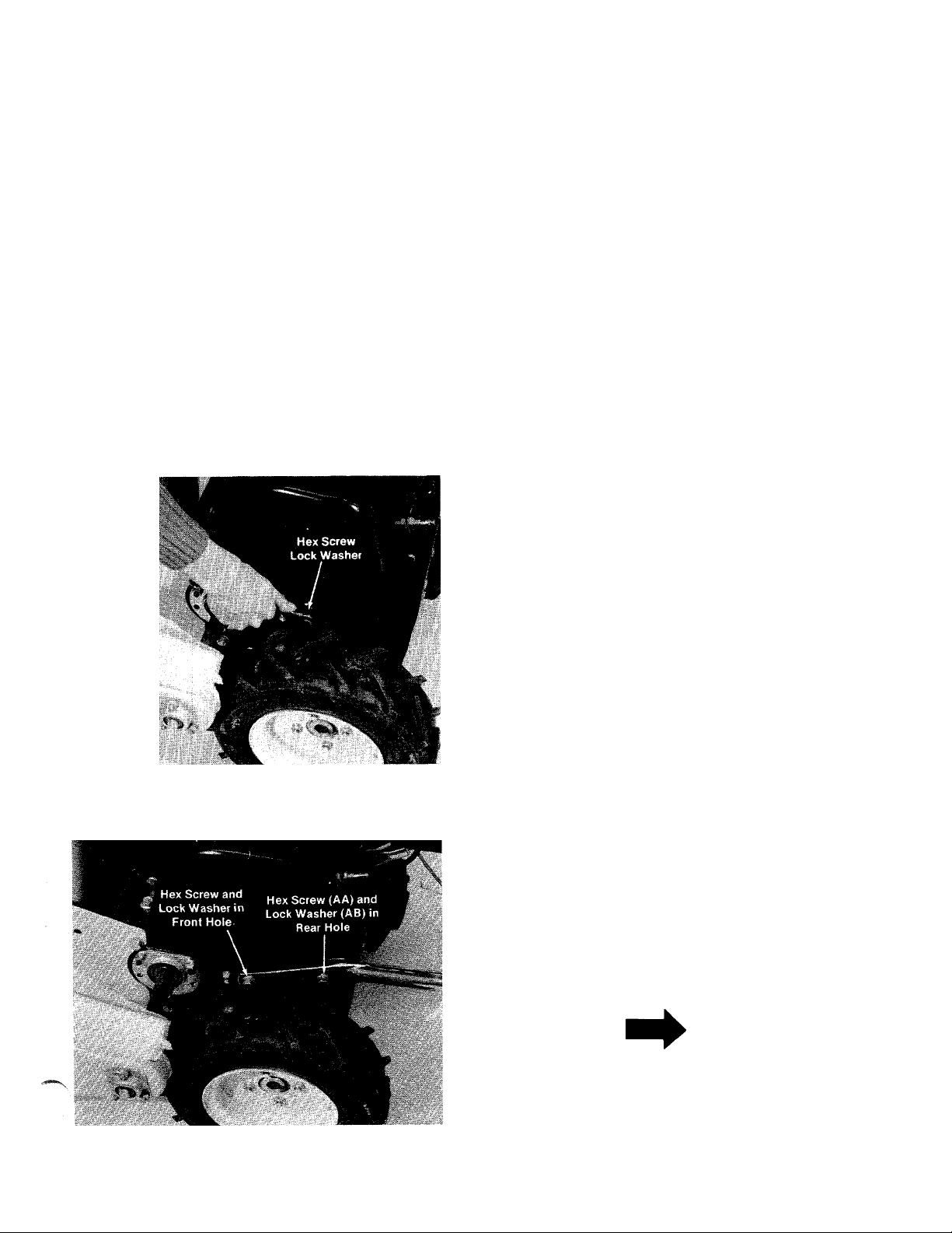
3. To attach handle assembly to the snow
— thrower, first remove the hex screw and lock
washer from each side of snow thrower
housing. A 9/16” wrench is required. See
figure 4.
4. Fasten handle assembly to snow thrower
housing. Place lock washer (AB) on hex screw
(AA). Line up holes in handle with holes in
sides of snow thrower housing. Start hex
— screws into rear holes by hand. Replace hex
screw and lock washer in front hole. See
figure 5. Do not tighten at this time.
NOTE
Loosen the three hex nuts which
hold the handle panel to the handle.
This will permit handle to move
freely so it can be assembled to the
housing with greater ease. Leave
hex nuts loose.
Page 6
FIGURES.
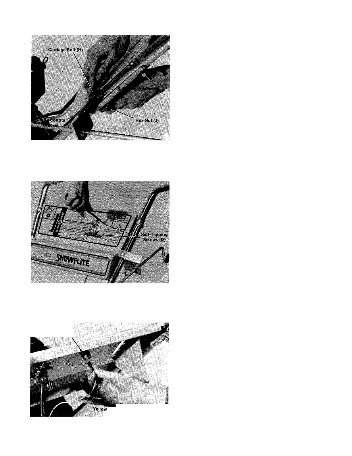
5.--Attach chute crank assembly to unit. Line up
hole in chute control bracket with hole in
handle. Secure with carriage bolt (H),
belleville washer (I) and hex nut (J) as shown
----
in figures.
6. At this point, tighten secureiy all nuts and
bolts.
7. Hold throttle control underneath handle
panel. Bring throttle control knob through the
slot in handle panel. Line up the two holes in
the throttle control with the two holes in
handle panel. Secure with self-tapping screws
(D). A screwdriver is required. See figure 7.
FIGURE 7.
FIGURES.
Safety
Switch
8. Plug yellow electric wire into safety switch
— beneath handie panei. See figure 8.
Electric
Wire
Page 7

FIGURES.
Shift Lever
(Flared Edge
Facing Detents
in Handle Panel)
Washer (W)
fl Compression
Spring (V)
Handle Panel
Weld Bolt
Belleville
9. Place shift lever (S) through slot in handle
panel, making sure flared edge of shift lever
faces the detents on handle panel. See figure
9.
10. Place shift lever on handle panel weld bolt.
------
Secure with belleville washer (W) (cupped
side goes against shift lever), compression
spring (V) and elastic lock nut (U). See figure
9. Tighten lock nut until compression spring
holds the shift lever into detent slots on
handle panel.
FIGURE 10.
ê
i
V
Ék/
11. Place bent end of shifting rod up through
shifting bracket located on right side of unit
(see figure 10). Secure with flat washer (0)
and cotter pin (M).
12. Move shifting bracket to middle (neutral)
position. Roll the unit back and forth. It
should move freely.
13. Place shift lever in neutral position. Thread
ferrule (N) onto shifting rod and place into
shift lever. Roll unit back and forth, checking
to be sure it is in neutral gear. If it does not
move freely, remove the ferrule and thread in
___
or out as necessary. Replace the ferrule and
move the unit again. Repeat procedure as
needed until neutral position is reached.
¡
14. After unit is set in neutral, secure ferrule to
shift lever with cotter pin (M) as shown in
figure 11.
FIGURE 11.
Page 8
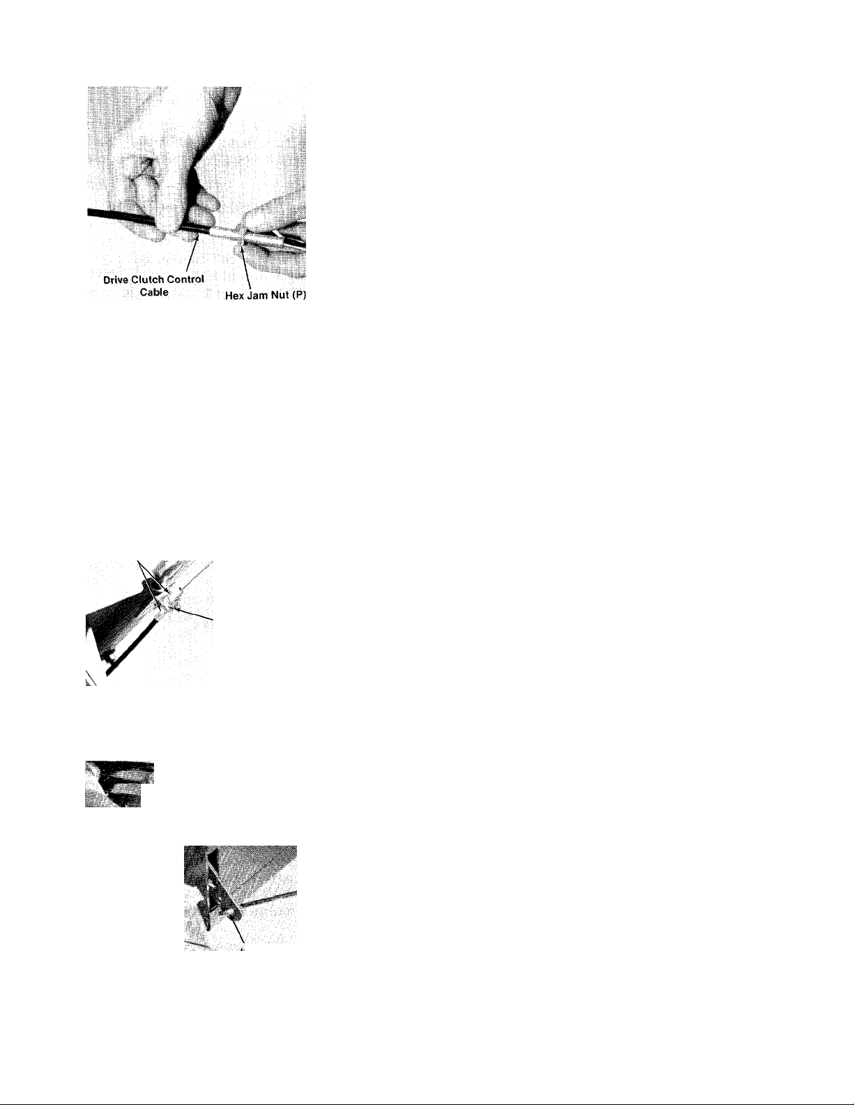
FIGURE 12.
“Z” End of Control
Wire Hooked in
Clutch Grip
I
/
Drive Clutch
Grip
15. Thread hex jam nut (P) onto drive clutch
___
control cable which is attached to the snow
thrower housing. See figure 12.
16. Thread end of clutch control cable through
cable support bracket on right handle. Place
lock washer (Q) and hex jam nut (P) over
clutch control cable. Start nut on cable
housing by hand.
17. Hook “Z” end of control wire through hole in
drive clutch grip assembly. See figure 13.
Hex Jam
Nut (P)
FIGUREIS.
■M
\
Control Wire is
straight
Lock Washer (Q)
.'W
*t, I™/
Z” End of Clutch
Rod Assembly
18. Hold clutch grip so that the grip is against the
_
handle as shown in figure 13. Adjust the
clutch control cable so that the slack is taken
out of the control wire. Tighten the two hex
nuts at the cable support bracket. Control
wire should now be straight.
A
CAUTION
Do not overtighten control wire.
Too much tension may cause it to
break.
19. Auger clutch rod assembly and lockout rod
are preassembled. Place “Z” end of clutch rod
assembly into hole in clutch bracket on left
side of unites shown in figure 14.
FIGURE 14.
Page 9
■íi'ít .
Lockout
Rod
FIGUREIS.
A
Auger Clutch
Grip
Auger Clutch
Grip Assembly
20. Hook lockout rod into auger clutch
------
assembly (E) as shown in figure 15.
grip
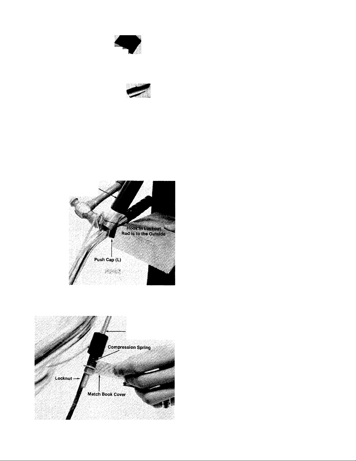
21. Place auger clutch grip on left handle (hook in
lockout rod is to the outside). Secure with
clevis pin (K) and push cap (L), using a
-----
hammer and a block of wood as shown in
figure 16.
mm
FIGURE 16.
FIGURE 17.
Lockout Rod
22. Squeeze the auger clutch grip to engage
lockout rod so you can check for correct
adjustment. With the lockout rod engaged,
you should be able to get a match book cover
------
between the coils of the compression spring
(spring should not be compressed tightly). If
there is not space between spring coils,
adjust the locknut using a 7/16” wrench until
correct adjustment is reached. See figure 17.
Page 10

Keeper (B) Beneath Lip *
FIGUREIS.
liex Lock Nuts (C)
V
Chute Flange
j
Grease the chute opening.
Place chute assembly over chute opening.
Place chute flange keepers (B) beneath lip of
chute assembly. Secure with hex lock nuts
(C) as shown in figure 18. Tighten with a
7/16” wrench, then back off 1/4 turn to allow
easier movement.
25. Grease the teeth on the chute assembly.
26. Place the end of chute crank assembly into
slot provided. Slide worm and bracket on
chute crank assembly into teeth on chute
assembly. Fasten in position with belleville
washer (F) (cupped side up) and hex nut (G).
See figure 19. Tighten finger tight.
Belleville Washer (F)
Hex Nut (G)
FIGURE 19.
Drift Cutli r
27. Turn chute crank to see that chute moves
freely. If adjustment is necessary, slide worm
and bracket in or out. Then tighten hex nut
securely with a|HB|wrench.
'A"
28. Loosen hex nut holding drift cutter to unit.
■
\
■
Pivot into position. Insert carriage bolt (X)
------
through snow thrower housing and drift cutter
with head to the inside of housing. Secure
with lock washer (Y) and hex nut (Z). Tighten
securely. See figure 20.
FIGURE 20.
10
Page 11

Throttle Control
Cable
FIGURE 21.
OPERATION
CONTROLS
29. Secure yellow electric wire to throttle control
•cable with the vinyl tape (T) provided. See
figure 21.
Shift Lever (See Figures 22 and 23)
The shift lever is located on the right hand side of
the handle panel. The shift lever may be moved
into forward, neutral or reverse position.
A. Center Position (N) is Neutral.
B. Forward Position (F) is Forward.
C. Rear Position (R) is Reverse.
Auger Clutch
i
F
t
0
1
FIGURE 22.
FIGURE 23.
11
Page 12

Safety Ignition Switch (See figures 22 and 24)
The ignition key must be in the switch and turned
to the on position before the unit will start.
Auger Clutch (See figures 22 and 27)
The auger clutch is located on the left handle.
Squeeze the clutch grip to engage the augers.
Release to stop the snow throwing action.
FIGURE 24.
Throttle Control (See figures 22 and 25)
The throttle control is located on the left hand
side of handle panel..It regulates the speed of the
engine.
THROTTLE
FIGURE 25.
Drive Clutch (See figures 22 and 26)
The drive clutch is located on the right handle
Squeeze the clutch grip to engage drive. Release
to stop.
'squeeze lever
TO ENGAGE
AUGER
CLUTCH
FIGURE 27.
Chute Crank (See Figure 22)
The chute crank is located on left hand side of the
snow thrower.
To change the direction in which snow is thrown,
turn chute crank as follows:
1. Crank clockwise to discharge to the ieft.
2. Crank counterclockwise to discharge to the
right.
STARTING INSTRUCTIONS
1. Remove oil fill cap. Add oil until reaching
point of overflowing. See figure 28.
SQUEEZE LEVER’
FIGURE 26.
O'
TO ENGAGE
DRIVE
CLUTCH
FIGURE 28.
12
Page 13

Above Freezing Temperatures: Use oil with
viscosity grade SAE 30 or SAE 10W-30 or SAE
10W-40.
Below Freezing Temperatures: Use oil with
viscosity grade SAE 5W-30 or SAE 10W.
2. Fill fuel tank with fresh, clean unleaded or
regular gasoline.
I WARNING \
Never fill fuel tank indoors, with en
gine running or while engine is hot.
3. Attach spark plug wire to spark plug.
4. Insert ignition key and turn to “ON” position.
5. Place shift lever in “NEUTRAL” (N) position.
6. Place throttle control in “START” (fast)
position.
2. Push primer two (2) or three (3) times.
See figure 30.
NOTE
Additional priming may be required
(for initial start only) if temperature
is below 15°F.
J WARNIN^
Never run engine indoors or in en
closed poorly vented area. Engine
exhaust gases contain carbon mon
oxide: an odorless and deadly gas.
7. Start engine, following appropriate instruc
tions:
A. Cold engine start (engine has not been run
recently)
1. Pull choke wire out to “ON” position.
See figure 29.
FIGURE 30.
3. Grasp the starter rope handle and pull
out rapidly. Return rope handle slowly.
Repeat until engine starts. If engine
fails to start, repeat steps 2 and 3 as
necessary until engine starts.
4. After engine starts, push choke wire in
gradually (to “OFF” position).
B. Warm engine start (engine still warm from
recent running)
1. Grasp the starter rope handle and pull
out rapidly. Return rope handle slowly.
Repeat until engine starts.
2. If engine fails to start after a number of
attempts, pull choke wire out. Repeat
step one until engine starts. After
engine starts, push choke wire in
gradually.
WARNING \
FIGURE 29.
Once the snow blower has been in
operation, caution should be exer
cised in the area of the muffler
and surrounding surfaces. See fig
ure 31.
13
Page 14

FIGURE 31.
TO STOP ENGINE
ADJUSTMENTS
^ WARNING J
NEVER attempt to clean chute or
make any adjustments while engine
is running.
CHUTE ASSEMBLY ADJUSTMENT
The distance snow is thrown can be adjusted by
adjusting the angle of the chute assembly. The
sharper the angle, the shorter the distance snow
is thrown.
NOTE
Run engine for a few minutes before
stopping to help dry off any mois
ture which may have accumulated
on the recoil starter.
1. Move throttle control lever to “STOP” posi
tion.
2. Turn ignition key to “OFF” position.
3. Remove ignition key to prevent accidental
starting.
A
Disconnect spark plug wire from
spark plug and secure it so that
it cannot accidentally contact spark
plug. This will reduce the possibility
of unauthorized starting of engine
while equipment is unattended.
TO ENGAGE DRIVE
CAUTION
To adjust chute assembly, loosen the hand knob.
Pivot the top of the chute assembly to position
desired. Retighten the hand knob.
SKID SHOE ADJUSTMENT
The space between the shave plate and the ground
can be adjusted. For close snow removal, place
skid shoes in the low position. Use middle or high
position when area to be cleared is uneven. See
figure 32.
To adjust skid shoes, loosen the four hex nuts and
carriage bolts. Move skid shoes to desired
position. Retighten nuts and bolts securely.
1. With the engine running near top speed, move
shift lever into forward (F) or reverse (R)
position. (If the lever does not shift easily,
move the unit back and forth to align gears as
you shift the lever.)
2. Squeeze the drive clutch grip (located on the
right handle) and the snow thrower will move.
Release it and the drive motion will stop.
CAUTION
A
NEVER move shift lever without first
releasing the drive clutch.
' High Position
' Middle Position
- Low Position
Skid Shoe
FIGURE 32.
14
Page 15

AUGER CHAIN ADJUSTMENT
If the drive chain to the auger is loose, it may be
adjusted using a 9/16” wrench. Loosen the hex
nut on the outside of the chain guard on the left
hand side of the unit. Slide the bolt down as
necessary. Tighten the hex nut securely. See
figure 33.
Loosen the two hex nuts at the wheel axle on the
right hand side of snow thrower housing. Lift up
on the right wheel to take the slack out of the
chain as you retighten the nuts. See figure 34.
SHIFTING ROD ADJUSTMENT
To adjust the shifting rod, refer to step number 13
under assembly instructions.
DRIVE CLUTCH CONTROL ADJUSTMENT
To adjust the drive clutch control, refer to step
number 18 underassembly instructions.
Hex Nut
Chain Guard
FIGURE 33.
REAR AXLE CHAIN ADJUSTMENT
To adjust the rear axle chain, first tip the snow
thrower forward so it rests on the auger housing
and drift cutters.
Lift Right
Hand Wheel
AUGER CLUTCH CONTROL ADJUSTMENT
To adjust the auger clutch control, refer to step
number 22 under assembly instructions.
FIGURE 34.
15
Page 16

LUBRICATION
SPECIFICATIONS:
Lubricate once a season or after every 25 hours of
operation.
Oil—Use SAE 30 or equivalent.
Grease—Use automotive multi-purpose grease.
Lubricate chain once a season with engine oil.
Engine—Remove oil fill plug and add oil until it
reaches point of overflowing.
Grease Worm On Chute
Crank Once a Season
Change Oil—After first two (2) hours of operation
and every twenty-five (25) hours thereafter. Drain
oil from oil drain plug.
Above Freezing Temperature: Use oil with
viscosity grade SAE 30, or SAE 10W-30, or SAE
10W-40.
Below Freezing Temperature: Use oil
viscosity grade SAE 5W-30 or SAE 10W.
Capacity—Approximately VA pints.
with
Grease Chute Opening Once
A Season
Oil all chains, bearings, gears and the shifting
mechanism at least once a season , Use engine
oil. Avoid getting oil on V-belts and pulleys.
16
Page 17

,-<^^***'*N
MAINTENANCE
SHAVE PLATE AND SKID SHOES
The shave plate and skid shoes on the bottom of
the snow thrower are subject to wear. They should
be checked periodically and replaced when
necessary.
To remove shave plate, remove the csrriage bolts,
lock washers and hex nuts which attach it to the
snow thrower housing. Reassemble new shave
plate, making sure heads of the carriage bolts are
to the inside of the housing. Tighten securely.
To remove skid shoes, remove the four carriage
bolts, belleville washers and hex nuts which
attach them to the snow thrower. Reassemble
new skid shoes with the four carriage bolts,
belleville washers (cupped side goes against skid
shoes) and hex nuts.
BELT REMOVAL AND REPLACEMENT
^ WARNING {
Remove the spark plug wire from the
spark plug and ground. Drain gaso
line from the fuel tank, or place a
piece of plastic film underneath
the gas cap to prevent gasoline from
leaking.
Remove the belt keeper by removing the self
tapping screw shown in figure 36. A 9/16”
wrench is required.
FIGURE 36.
3. Tip the snow thrower forward so that it rests
on the auger housing and drift cutters.
4. Remove bottom cover. First remove the two
self-tapping screws shown in figure 36 with a
Va” wrench. Then lift cover out from the slots
in the frame. See figure 37.
To remove and replace either the auger drive belt
or the drive belt, proceed with the following
instructions.
1. Remove the three self-tapping screws from
the belt cover using a 7/16” wrench. See
figure 35.
I§elf -Tapping
' Screw
Belt Cover
FIGURE 35.
FIGURE 37.
5. Remove the large shoulder bolt which acts as
a belt keeper by removing the hex nut and lock
washer on the outside of the frame assembly.
A 9/16” wrench is required. See figure 38.
17
Page 18

FIGURE 38.
6. Remove the belt guard plate by removing the
self-tapping screw shown in figure 38. Hold
one hand underneath the frame to catch the
plate so it does not fall. A Vz" wrench is
required. See figure 39.
me:»
Auger Drive ■
Belt
Large Bottom
Pulleys
Drive Belt ^
Se^-Tappirjg
c. Slide the belt off the bottom pulley and out
the bottom of the chain case.
Auger Drive
Bell Idler Pulleys'^
FIGURE 40.
9. To Reinstall Drive Belt:
a. Slip belt over engine pulley.
b. Place belt between belt guard pin and idler
pulley. See figure 40.
c. Feed belt over large bottom pulley.
10. To Reinstall Auger Belt:
a. Slide belt in from bottom.
b. Slip belt over engine pulley.
c. Place between belt guard pin and idler
pulley. See figure 40.
d. Feed belt over large bottom pulley.
11. Reinstall belt guard plate. Hold It in place
beneath frame In one hand. Secure with self
tapping screw, using a 1/2” wrench. See
figure 41.
r
FIGURE 39.
7. To Remove Auger Drive Belt:
a. Slip auger drive belt off engine pulley. See
figure 40.
b. Lift belt out of the sheave of the bottom
pulley.
c. Slide belt out the bottom of the chain case.
8. To Remove Drive Belt:
a. First slip the auger drive belt off the engine
pulley as shown in figure 40.
b. Slip the drive belt over the double engine
pulley.
Belt Guard
Plate
FIGURE 41.
18
Page 19

12. Reinstall shoulder bolt (which acts as a belt
keeper) at the base of the two large pulleys. A
9/16” wrench is required. Tighten securely.
13. Reinstall bottom cover by slipping it into the
two slots in frame provided. Secure with two
self-tapping screws, using a Vz" wrench.
If unit is to be stored over 30 days, prepare for
storage as follows;
1. Remove all gasoline from fuel tank to prevent
gum deposits from forming on these parts
and causing possible malfunction of engine.
14. Tip unit into operating position.
15. Reinstall belt guard and belt cover.
16. Remove plastic film from gas cap.
A
Check engine and snow thrower fre
quently for loose nuts, bolts, etc.,
and keep these items tightened.
CAUTION
OFF SEASON STORAGE
^ WARNING I
NEVER STORE ENGINE WITH FUEL IN TANK
INDOORS OR IN ENCLOSED, POORLY VENTI
LATED, ENCLOSURES, WHERE FUEL FUMES
MAY REACH AN OPEN FLAME, SPARK OR
PILOT LIGHT AS ON A FURNACE, WATER
HEATER, CLOTHES DRYER, ETC.
I WARNING \
DRAIN FUEL INTO APPROVED CONTAINER
OUTDOORS, AWAY FROM OPEN FLAME.
Run engine until engine starts to falter, then use
choke to continue engine operation until all fuel in
tank and carburetor is exhausted. Remove fuel
line at tank or carburetor and drain any remaining
gasoline from system.
CAUTION
A
FUEL LEFT IN ENGINE DURING WARM
WEATHER DETERIORATES AND WILL CAUSE
SERIOUS STARTING PROBLEMS.
2. Remove spark plug and pour one (1) ounce of
engine oil through spark plug hole into
cylinder. Crank engine several times to
distribute oil. Replace spark plug.
3. Clean unit by removing any dirt from exterior
of engine and equipment.
4. Follow lubrication recommendations on page
16.
19
Page 20

310-430A
IF YOU WRITE TO US ABOUT THIS ARTICLE
OR IF YOU ORDER REPLACEMENT PARTS AL
WAYS MENTION THIS MODEL 4 SERIAL NO
MODEL
Page 21

PARTS LIST FOR MODEL 310-430A
REF.
NO.
1
05506 Drive Clutch Grip Ass’y.
2
01166
4
711-0415 Clevis Pin .375 Dia. x 1.62
PART
NO.
COLOR
CODE
DESCRIPTION
Grip 33 736-0231
NEW REF.
PART
Lg.
5 711-0677
6
725-0201
7
725-0464 ignition Switch 36 05811
Adjustment Ferrule
Ignition Key
8 736-0225 Internal L-Wash. 5/8” Scr.*
9 746-0312
10
710-0227
11
T«-5yi
12
05507
13
726-0110 Push Cap .375” Rod—Black
14 736-0242
15 712-0267
16
736-0140 FI-Wash. .385I.D. X.62
Throttle Control Ass’ySelf Tap. Scr. #8x .50” Lg.
Curved Carriage Bolt
5/16-18x«BI/-75lia-
Auger Clutch Grip Ass’y.
Belleville Wash.
Hex Nut 5/16-18 Thd.*
O.D. X .060 45 725-0480
17 720-0171
18
726-0100 Push Nut 3/8” Rod
19 747-'0t53^1w
20
05567
21
05516
22
732-0337
23
749-0203 Handle—L.H.
24
05816 Handle Panel Ass’y.
25
747-0154 Lockout Rod .214 Dia. x
Black Knob—3/8” Dia. Hole 46 725-0476
Chute Crank
Auger Clutch Rod Ass’y.
Chute Control Bracket
Compression Spring .39 O.D.
X .75” Lg.
N
32.0” Lg.
26
27
73^1^ L-Wash.3/8” Scr.*
28
732-0320
Pilot Scr. 3/8-16 xBl’Lg.
Extension Spring .38 O.D.
X3.25 Lg.
29 710-0600 Hex Wash. Hd. Self Tap Scr.
5/16-24 X .50” Lg.
30 05790
710-0322
31
Frame Cover
Hex Sems Scr. 5/16-18 x
N
1.00” Lg.*
NO.
32
COLOR NEW
NO.
748-0233
CODE
DESCRIPTION
Shoulder Spacer
PART
FI-Wash. .34I.D. xl.12
O.D. X .125
34
736-0119
35 712-0158
L-Wash. 5/16” Scr.*
Hex Cent. L-Nut 5/16-18
Thd.
Shifting Bracket
37 714-0111
Cotter Pin 3/32” Dia. x 1.00
Lg.
38 736-0159
FI-Wash. .344I.D.X.88
O.D. X .063
749-0204
39
40 05559
712-0324 Hex Ins. L-Nut V4-20 Thd.
41
42 736-0173
43 747-0175
746-0374 Drive Clutch Control Cable
44
Handle—R.H.
Thrower Clutch Bracket
FI-Wash. .28 I.D. x .75 O.D.
Shifting Rod
Vinyl Sealing Tape
Electric Wire
47
710-0458
Carriage Bolt 5/16-18 x
1.75” Lg.*
48 712-0116
Hex Ins. Jam L-Nut 3/8-24
Thd.*
49
732-0193
Compression Spring .60
O.D. X .88” Lg.
50
736-0105
Belleville Wash. .40 I.D. x
.88 O.D.
05694 Shift Handle Ass’y.
52
53
05^
55 tTOb
Cable Support Bracket
He)^el^^^c^7W^
.75” Lg.
56 726-0195
57
“U”-Nut 3/8-16 Thd.
Hex Jam Nut 5/16-24 Thd.
PART
N
N
N
'For faster service obtain standard nuts, boits and washers localiy. if these items cannot be obtained locaiiy, order by part
number and size as shown on parts list.
(488—Mack Truck Yellow)
When ordering parts if color or finish is important, use color code shown at left. (e.g. Mack
Truck Yellow Finish—05546 (488).)
The engine is not under warranty by the Snow Thrower
manufacturer. If repairs or service is needed on the
engine, please contact your nearest authorized engine
service outlet. Check the “Yellow Pages” of your
telephone book under “Engines—Gasoline.”
NOTE
This instruction manual covers various
models and all specifications shown do not
necessarily apply to your model. Specifica
tions subject to change without notice or
obligation.
21
Find It Fast
In The
Yellow Pages
Page 22

310-430A
/ 2
h./ /
22
Page 23

PARTS LIST FOR MODEL 310-430A
COLOR
REF.
PART
NO.
NO.
1 734-0988
CODE
DESCRIPTION
Wheel Ass’y.—Comp. 12.50
X3.50—R.H.
734-0987
Wheel Ass’y.—Comp. 12.50 x
3.50—L.H. (Not Shown)
710-0409
2
Hex Scr. 5/16-24x1.75” Lg.
H.T.
05811
3
4 738-0140
712-0158
5
Shifting Bracket
Shid. Scr. .438” Dia. x .180
Lg-
Hex Cent. L-Nut 5/16-18
6 Shifting Bracket Support
7 710-0600
Hex Wash. Hd. Self-Tap Scr.
5/16-24 X .50
714-0111
8
Cotter Pin 3/32” Dia. x
1.00” Lg.
736-0187
9
10
11
748-0229
715-0114
FI-Wash. .64 I.D. X 1.25 O.D.
X .060
Hex Flange Brg. .63 I.D.
H-Spring Pin Spri. V4” Dia.
xl.50 Lg.
05792
12
Drive Housing Bracket—
R.H.
714-0104
13
14 748-0163
15 748-0161
05054
16
738-0315
17
748-0164
18
713-0263
19
Internal Cotter Pin 3/8” Dia.*
Spur Gear—21 Teeth
Clutch Collar
Shifting Yoke
Rod
Sprocket—10 Teeth
#41 Chain—V2” Pitch x33
Links
20
713-0723
05093
Master Link
28 Teeth—Sprocket Hub
Ass’y.
21
750-0229
Spacer—.62 I.D. x .88 O.D.
1.030
736-0237
22
FI-Wash. .64 I.D. X 1.25
O.D. X .100
738-0459
23
24
714-0137
Shifting Shaft
Hi-Pro Key 3/16 X 3/4” Dia. x
1.062
05137
25
26 710-0506
27 756-0325
32 Teeth Sprocket Hub Ass’y.
Hex Scr. V2-20 X 5.50” Lg.
5.25” O.D. Pulley with 9
Teeth Sprocket
738-0314 Shaft
28
NEW
PART
N
N
REF.
NO.
29
713-0265
713- 0723
30
714- 0126
31
714-0129
32
05789
33
741-0133
34
05034
35
736-0329
36
712- 0287
37
750-0295
38
736-0250
39
748-0162
40
738-0460
41
713- 0261
42
736-0921
43
712-0200
.44
10470
716-0104
45
46
47
736-0287
48
712-0267
49
736-0119
50
710-0451
51
748 085»
52
710-0190
53
750-0324
54
736-0119
55
712- 0267
56
713- 0264
713-0723
57
712-0273
PART
COLOR
NO.
CODE
7/3'-OZ7B
DESCRIPTION
#41 Chain 1/2 Pitch x 47
Links
Master Link
Hi-Pro Key—3/16 X 3/4” Dia.
Hi-Pro Key—3/32x5/8”
Dia.
Drive Housing Bracket
Ass’y- —L.H.
Ball Bearing .500 I.D. x 1.38
O.D. x .438
Bearing Housing
L-Wash. 1/4 Scr.*
Hex Nut 1/4-20 Thd.*
Spacer—.52 I.D. x .62 O.D.
X2.69
FI-Wash. 1.06 I.D. X 1.75
O.D. X .100
Spur Gear—62 Teeth
Wheel Axle
32 Teeth—Sprocket Hub
Ass’y.
L-Wash. for 1/2” Scr.*
Hex Ins. Jam L-Nut V2-2O
Thd.
Bearing Plate
E-Ring for .500” Dia. Shaft
Flange Bearing w/Flats
.753
FI-Wash. .81 I.D. X 1.25
O.D. X .060
Hex Nut 5/16-18 Thd.*
L-Wash. 5/16” Scr.*
Carriage Bolt 5/16-18 x .75”
Lg.
8 Teeth Sprocket #41 Chain
Hex Scr. 5/16-18x4.00” Lg.
Spacer .50 O.D. x .34 I.D. x
3.25” Lg.
L-Wash. 5/16” Scr.*
HexNut5/16-18Thd.*
#41 Chain 1/2 Pitch x 37 Links
Master Link
Hex Jam L-Nut 5/16-24 Thd.
NEW
PART
N
N
N
N
N
'For faster service obtain standard nuts, bolts and washers locally. If these items cannot be obtained locally, order by part
number and size as shown on parts list.
(488—Mack Truck Yellow) When ordering parts if color or finish is important, use color code shown at left. (e.g. Mack
Truck Yellow Finish—05546 (488).)
The engine is not under warranty by the Snow Thrower
manufacturer. If repairs or service is needed on the
engine, please contact your nearest authorized engine
service outlet. Check the “Yellow Pages” of your
telephone book under “Engines—Gasoline.”
23
Find It Fast
In the
Yellow Pages
Page 24

310-430A
40 ö
60 59 ®
24
Page 25

REF
NO
PART
COLOR
NO.
CODE
1
_
2 710-0599
05621
3
4 714-0105
5 710-0600
6 05810
05821
7
8 736-0119
9 710-0237
10 746-0374
11 736-0234
12
712-0116
13 754-0205
14 756-0257
15 736-0235
16 736-0169
17 710-0152
18
710-0723
756-0137
19
712-0107
20
21
05823
05556
22
712-0266
23
714-0111
24
747-0174
25
748-0233
26
05559
27
710-0322
28
29 738-0281
30
712-0158
31 736-0231
32 712-0266
33
34
35 710-0606^
05156
36
37
741-0155
38 713-0266
39 713-0723
40 712-0267
41
710-0600
05244
42
74^17^^^
43
44
45 71^79^^"
46 756-0258
47 756-0325
738-0117
48
PARTS LIST FOR MODEL 310-430A
DESCRIPTION
Engine
Hex Self-Tap Scr. V4-20 x .50”
Lg-
Belt Cover N
Sq. Key 3/16x1.00” Lg.
Hex Wash. Hd. Self-Tap Scr.
5/16-24 X.50” Lg.
Belt Guard N
Engine Plate Ass’y. N
L-Wash. 5/16” Scr.*
Hex Scr. 5/16-24 X ;62” Lg.
Drive Clutch Control Cable N
FI-Wash. .391.D. X 1.50
O.D. X .060
Hex Ins. Jam L-Nut 3/8-24
Thd.
3V-Belt31.5” Lg.
Engine Pulley
FI-Wash. .40 I.D. X 1.25 O.D.
X .157
L-Wash; 3/8” Scr.*
Hex Scr. 3/8-24x1.00” Lg.*
Hex Scr. 3/8-.^iJx1.25” Lg.*
Flat Idler 2.25 O.D. , , i u, v
Drive Idler Brkt. Ass’y.
Thrower Idler Brkt. Ass’y.
Hex Cent. L-Nut 3/8-16 Thd.
Cotter Pin 3/32” Dia. x 1.00”
Lg.*
Clutch Rod 5/16” Dia. x
2.88 Lg.
Shoulder Spacer
Thrower Clutch Bracket
Hex Sems Scr. 5/16-18 x
1.00” Lg.*
Shid. Scr. .625” Dia. X.170”
Hex Cent. L-Nut 5/16-18
Thd.
FI-Wash. .34 I.D. xl.12
O.D. X .125
Hex Cent. L-Nut 3/8-16 Thd.
Woodruff Key 5/32 x 5/8 Dia.
jUirower Shaft
Hex Scr. V4-20x1.50” Lg.*
14 Teeth Sprocket Hub Ass’y.
Ball Brg. .625 I.D. X 1.38
O.D. X .438
#41 Chain —V2” Pitch X 83
Links
#41 Master Link Va” Pitch
Type II
Hex Nut 5/16-18 Thd.*
Hex Wash. Hd. Self-Tap Scr.
5/16-18 X .50” Lg.
Bearing Housing
Self Aligning Brg. .750 I.D.
~
.. .......
. .. ... .. . .. ... .. . .. ... .. . 7 ”ee ^
Hex Nut 3/8-16 Thd
1/2” V-Pulley .753 I.D.
5.25” O.D. Pulley with 9
Teeth Sprocket
ShId. Scr. .498” Dia. x 2.475”
Lg.
NEW
PART
N
25
REF.
NO.
49
710-0623
50
736-0231
51
712-0254
710-0538
52
736-0242
53
54
05561
55
710-0260
56
05139
57
07386
58
710-0371
59
712-0798
60
736-0105
05571
61
62
710-0389
63
05540 —488
64
05001
741-0170
65
66
738-0227
67
05018
68
05515
05482 —488
69
70
710-0276
71
05225 —488
72
736-0179
736-0242
73
74
09966
75
712-0158
76
715-0103
77
736-0179
78
717-0301
79
747-0153
80
05783
736-0242
81
82
05785
83
05673
84
710-0726
85
710-0442
732-0264
86
87
710-0560
88
736-0235
89
750-0252
90
736-0219
756-0192
91
92
712- 0130
93
713- 0177
PART
NO.
COLOR
CODE
DESCRIPTION
Hex Self-Tap Scr. 3/8-16 x
.75” Lg.
FI-Wash. .341” I.D. xl.12”
O.D.
Hex Jam Nut 5/16-24 Thd.*
Hex Lock Screw 5/16-18 x
.62” Lg.
Bell. Wash. .34I.D. X.88
O.D. X .060
Chain Guard
Carr. Bolt 5/16-18 X .62” Lg.*
Drift Cutters
FI-Wash.
Hex Scr. 5/16-18 X .88” Lg.
Hex Nut 3/8-16 Thd.*
Bell. Wash. .40 I.D. x.88
0. D.
Slide Shoe
Carr. Bolt3/8-16x.75”Lg.*
Spiral Housing Ass’y. 21”
Shave Plate
Flange Brg. w/Flats 1.0”
1. D.
Spiral Shaft
Spiral Ass’y.—L.H.
Chute Brkt.
Chute Ass’y.
Carr. Bolt 5/16-18x1.00”
Lg.*
Top Chute Ass’y.
FI-Wash. .53 I.D. X 1.25 O.D.
X .100
Bell. Wash. .34 I.D. x.88
O.D.
Handle Knob Ass’y.
Hex Cent. L-Nut 5/16-18
Thd.
Spring Pin Roll 1/8” Dia. x
.75” Lg.
FI-Wash. .531 I.D. X 1.25
O.D.
Worm—R.H. with Three
Thread
Chute Crank
Chute Flange Keeper Ass’y.
Bell. Wash. .34 I.D. x.88
O.D.
Frame Ass’y.
Belt Guard Plate
Hex Wash. Self-Tap Scr.
5/16-18 X .75” Lg.
Hex Scr. 5/16-18x1.50” Lg.*
Extension Spring .38 O.D. x
2.50” Lg.
Carriage Bolt 3/8-16 x 1.75”
Lg.
FI-Wash. .40 I.D. X 1.25 O.D.
Idler Spacer
Bell. Wash. .40 I.D. x 1.12
O.D.
Plastic Idler
Hex Ins. L-Nut 3/8-16 Thd.
40 Tooth Sprocket Hub Ass’y.
NEW
PART
N
N
N
Page 26

PARTS LIST FOR MODEL 310-430A (Continued)
REF.
NO.
PART
NO.
94 715-0118
COLOR
CODE
DESCRIPTION
Spring Pin Spiral 5/16 x
NEW
PART
1.75” Lg.
05136
95
05023
96
05017
97
05360 Bearing Hsg. Ass’y-
98
716-0121
99
Plastic Bushing
Spiral Plate
Spiral Ass’y.—R-H.
Snap Ring for 1.50” Dia.
Shaft
736-0163
100
FI-Wash. 1.0” I.D. xOHi
0.^.K,030
736-0250
101
FI-Wash. 1.06 I.D. X 1.75
O.D.
loz .3*i S. fi le. i% &» X .ofc
/Q% 73(s~ ^23S' . 7VJ^/’/ /Z^ Cff Tej^s^/c/x
26
Page 27

PARTS INFORMATION
POWER EQUIPMENT PARTS AND SERVICE
Parts and service for all MTD manufactured power equipment are
available through the authorized service firms listed below. All orders
should specify the model number of your unit, parts number,
desc'ription of ports ond the quontity of each part required.
ALABAMA BIRMINGHAM
Auto Electric & Carburetor Co
ARKANSAS FORT SMITH
Mity Mite Motors, Inc.................................4515 South 16th Street 72901
Sutton’s Lawn Mower Shop
CALIFORNIA PORTERVILLE
Billious.......................................................75 North D Street.... 93257
Lawn Mower Supply Co
J.W. Jewett Co.............................................981 Folsom St
COLORADO DENVER
South Denver Lawn Equip.........................527 West Evans
FLORIDA JACKSONVILLE
Radco Distributors
Small Eng. Dist..........................................2351 N.W. 147th St.... 33054
GEORGIA EAST POINT
East Point Cycle & Key.........................................2834 Church St.30344
ILLINOIS LYONS
Keen Edge Co.............................................8615 Ogden Ave
INDIANA ELKHART
Parts & Sales Inc
IOWA DUBUQUE
Power Lawn & Garden Equip
LOUISIANA NEW ORLEANS
Suhren Engine Co
MARYLAND TAKOMA PARK
Center Supply Co
MASSACHUSETTS SPRINGFIELD
Morton B. Collins Co
MICHIGAN LANSING
Lorenz Service Co........................................2500 S. Pennsylvania . 48910
Power Equipment Dist
MINNESOTA HOPKINS
Hance Distributing Inc
PowerTools Inc
MISSISSIPPI BILOXI
Biloxi Sales & Service, Inc
MISSOURI KANSAS CITY
Automotive Equip. Service.......................................3117 Holmes St 64109
Ross-Frazier Supply Co
Henzier, Inc..................................................2015 Lemay Ferry Rd.. 63125
NEW JERSEY BELLMAWR
Lawnmower Parts Inc.................................717 Creek Rd
Feld Distributor...........................................28 Glen Rd
NEW YORK CARTHAGE
Gamble Dist., Inc
................................................
......................................
................................................
..............................
..................................
.............................
.....................................................................
...................
NORTH LITTLE ROCK
......................
............................
...................
.....................
................................
.........................
.............................
SAN BERNARDINO
SAN FRANCISCO
OPA LOCKA
6867 New Hampshire Ave.. 20012
MOUNT CLEMENS
36463 South Gratiot.. 48043
ST. PAUL
3771 Sibley Memorial Hwy. . 55122
ST. JOSEPH
ST. LOUIS
RUTHERFORD
2625 4th Ave. S
Rt. 4 Box 368
25608 E. Baseline .... 92410
2403 Market St.32206
2101 Industrial Pkwy.. 46514
2551 J.F. Kennedy.... 52001
8330 Earhart Blvd.70118
300 Birnie Ave
420 Excelsior Ave. W.. 55343
506 Caillavet St
8th and Monteray .... 64503
...............
...................
.................
..............
............
................
..............
.................
.....................
West End Ave.13619
35233
72117
94107
80223
60534
01107
39533
08030
07070
BRIGGS AND STRATTON, TECUMSEH AND PEERLESS PARTS AND
SERVICE
Briggs & Stratton, Tecumseh and peerless parts and service should be
handled by your nearest authorized engine service firm. Check the
yellow pages of your telephone directory under the listing
Engines—Gasoline, Briggs & Stratton or Tecumseh Lauson.
GTP Leisure Products Inc
NORTH CAROLINA GOLDSBORO
Smith Hardware Co...............................r. 515 N. George St. .. 27530
Dixie Sales Company
OHIO CARROLL
Stebe’s Mid-State Mower Supply ... Box 366-71 High St. ..43112
Bleckrie, Inc
National Central
Burton Supply Co
OKLAHOMA ADA
Ada Auto Supply
Victory Motors, Inc
Forest Sales Inc......................................... 1039 NW 63rd St
OREGON PORTLAND
Kenton Supply Co
PENNSYLVANIA CHESTER
Stull Equipment Corp
EECOInc.....................................................4021 N.ethSt
Thompson RubberCo................................5222-24 N. Fifth St.... 19120
Bluemont Co
TENNESSEE KNOXVILLE
Master Repair Service................................2000 Western Ave. ... 37921
Memphis Cycle & Supply Co.....................421 Monroe Ave
American Sales & Service, Inc
TEXAS DALLAS
Marr Brothers, Inc......................................423 E. Jefferson
Woodson Sales Corp................................. 1702 N. Syivania............76111
Bullard SuDply Co
Catto & Putty, Inc
UTAH SALT LAKE CITY
A-1 Engine & Mower Co
VERMONT BURLINGTON
Vermont Hdwe. Co. Inc
VIRGINIA RICHMOND
RBI Corp....................................................963 Myers St
WASHINGTON SEATTLE
Bailey’s Inc
WEST VIRGINIA CHARLESTON
Young’s, Inc
WISCONSIN APPLETON
Automotive Supply Co
..............................................
........................................
.............................................
................................................
...............................................
........................
....................................
............................
.......................................
....................................
...................................
................................
....................................
.......................................
............................
.............................
...............................
SYRACUSE
420 Marcellus St
GREENSBORO
327 Battleground Ave. 27402
CLEVELAND
7900 Lorain Ave
WADSWORTH
687 Seville Rd
YOUNGSTOWN
1301 Logan Ave. Box 929 . .44501
301 E. 12th St
MUSKOGEE
605 S. Cherokee
OKLAHOMA CITY
8216 N. Denver Ave. .. 97217
742 W. Front St
HARRISBURG
PHILADELPHIA
PITTSBURGH
11125 Frankstown Rd. 15235
MEMPHIS
..................
1922 Lynnbrook
FORT WORTH
HOUSTON
2409 Commerce St.... 77003
SAN ANTONIO
414 Live Oak
437 E. 9th St
180 Flynn Ave
1414 14th Ave
233 Virginia St., E
123 S. Lin wood Ave... 54911
...............
..................
..................
...............
...............
...................
...................
.................
...................
.................
...............
............
...........
..............
..............
.............
...........
13204
44102
44281
74820
74401
73116
19013
17110
38103
38116
75203
78298
84111
05401
23260
98102
25301
WARRANTY PARTS AND SERVICE POLICY
The purpose of warranty is to protect the customer from defects in workmanship and materials, defects which are NOT detected at the time of
manufacture. It does not provide tor the unlimited and unrestricted replacement of parts. Use and maintenance ore the responsibility of the
customer, The manufacturer cannot assume responsibility for conditions which it has no control. Simply put, if it's the manufacturer's fault, it's
the manufacturer's responsibility: if it's the customer's fault, it's the customer's responsibility.
CLAIMS AGAINST THE MANUFACTURER'S
WARRANTY INCLUDES
1. Replacement of Missing Parts on new equipment.
2. Replacement of Defective Partswithin the warranty period.
3. Repair of Defects within the warranty period.
All claims MUST be substantiated with the following information:
1. Model Number of unit involved.
2. Date unit was purchased or first put into service.
3. Date of failure.
4. Nature of failure.
MTD PRODUCTS INC • 5965 GRAFTON ROAD • P.O. BOX 36900 • CLEVELAND OHIO 44136
 Loading...