

Page 1

10 CENTS
Model Nos. 310-200
310-300 310-400 310-500
SNOW THROWER
For one year from date of purchase, MTD Products, Inc.,
will replace for the original purchaser, free of charge, F.O.B.
factory or authorized service firm, any part or parts found to
be defective in material or workmanship. All transportation
charges on parts submitted for replacement under this war
ranty must be paid by the purchaser. This warranty does not
include replacement of parts which become inoperative
through misuse, excessive use, accident, neglect, improper
maintenance or alterations by unauthorized persons. This
warranty does not include the engine, motor, battery, bat
tery charger or any component parts thereof. For service on
these units refer to the applicable manufacturer's warranty.
The above warranty will apply only to the original owner
and will be effective only if the warranty card has been pro
perly processed. It will not apply where the unit has been
used commercially.
Warranty service is available through your local author
ized service dealer or distributor. UNDER NO CIRCUM
STANCES WILL THE RETURN OF A COMPLETE UNIT
BE ACCEPTED BY THE FACTORY UNLESS PRIOR
WRITTEN PERMISSION HAS BEEN EXTENDED.
1. Know the controls and how to stop quickly—READ
THE OWNER'S MANUAL.
2. Disengage power and stop motor before cleaning dis
charge, removing obstacles, making adjustments, or
when leaving operation position.
3. Never direct discharge at bystanders nor allow anyone
in front of machine—debris may be hidden in the snow.
4. Keep children and pets a safe distance away.
5. Do not allow children to operate machine nor allow
adults to operate it without proper instruction.
6. Adjust height to clear gravel or crushed rock surface.
7. Exercise caution to avoid slipping or falling, especi
when operating in reverse.
a. Handle gasoline with care — it is highly flammable.
A. Use approved gasoline container.
B. Never add gasoline to a running motor — fill tank
out of doors and wipe up spilled gasoline.
C. Replace gasoline cap securely.
D. Open door if motor is run in garage — exhaust
gases are dangerous.
9. Disengage all clutches and shift into neutral before
starting motor. Keep hands, feet and clothing away
from power driven parts.
10. Use a grounded three wire extension cord for all plug
in electric units.
11. Keep machine in good operating condition and keep
safety devices in place.
MTD FRODUCTS I3SrC ® 5389 WEST noth ST. e P.O. BOX 2741 • CLEVELAND, OHIO 44111
FORM NO. 770-2837A
Page 2
ASSEMBLY (See Figure 4)
Right hand (RH) and left hand (LH) are as observed
from the operating position.
1. Assemble chrome handles to the frame with four hex
head cap screws 3/8—16 x 3/4 long and four lock-
washers 3/8”. DO NOT TIGHTEN.
2. Assemble handle panel to the handles with four
carriage bolts 1/4—20 x 1-1/2 long and hex locknuts
1/4—20 thread. Assemble handle panel so you can
read the instructions on the handle panel from the
operating position. LIFT HANDLE UP AS YOU
TIGHTEN ALL BOLTS AND NUTS ON THE
HANDLE ASSEMBLY.
3. The linkage arm for the transmission is located on
the RH side of the frame. Pull the arm back into
reverse. (Towards the operator.) If maybe necessary
to roll the snow thrower slightly until it engages in
the reverse position. Assemble the ferrule to the shift
lever handle use hole marked “21” on the handle panel
and screw in the shifting rod. Adjust the rod by screw
ing it in or out until it fits into the linkage arm on
the side of the frame. Secure it with a cotter pin.
4. Chute Crank. Assemble the chute crank (longest rod)
into the two holes in the handle panel being sure the
rod passes through the lock bracket. It may be
necessary to loosen the black knob on the handle
panel. Push the rod all the way through and assemble
it to the universal joint with a cotte pin.
5. Remove the wing nut, washer and carriage bolt
5/16—18 X 5/8 long from the chute assembly. Lift
the deflector and reassemble. If the deflector will
not move loosen the screw and nut slightly so it
pivot freely.
6. Attach the drift cutters to each side as shown on the
parts drawing.
CONTROLS
Main Clutch. This clutch shuts off the power to the
wheels and auger. When the handle is up it is in the
disengaged position. Always shut off the main clutch
when engaging and disengaging the auger clutch. It is
shown in the disengaged position in the photo.
(See Figure 1)
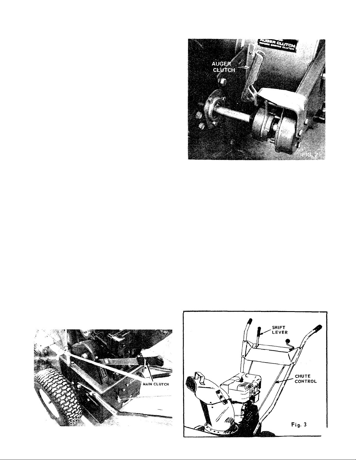
Auger Clutch is located on the right hand side of the
frame just behind the thrower housing. The clutch is
shown in the disengaged position.
When the handle is up the auger is disengaged. Do not
engage or disengage the clutch without disengaging the
main clutch. Disengaging the auger clutch allows you
to drive the snow thrower to and frqm the work area
without the auger turning. (See Figure 2).
It is not necessary to disengage auger clutch when start
ing. CAUTION—Main clutch must he disengaged when
starting.
Shift Lever. Move the shift lever into either forward or
reverse rapidly. Engaging slowly causes wear on the
clutch collars. There is no clutch to engage the drive
wheels.
To stop the snow thrower move the shift lever into
neutral (N). Move this control only when the engine is
operating. (See Figures/
Chute Controls. Release the lock and turn the crank to
rotate the chute. Loosen the wing nut to adjust the
deflector. (See Figure 3)
FORM NO. 770-2837B
FIG. 1
Page 3

PARTS LIST FOR MODELS 310-200, 310-300, 310-400, 310-500
Port
III.
-n
о
X
s
z
о
■D
5
z
Ч
m
D
No.
10
11
12
13
14
15
16
17
18
19
20
21
22
23
24
25
26
27
28
29
30
31
32
33
34
35
36
37
38
39
-.40
41 748-173
42
43
44
45
46
47
48
49
50
51
52
53
No.
748-162
1
310-5053
2
394-5137
3
716-106
4
5 715-108
748-227
6
736-1 16
7
748-852
8
716-104
9
711-355
394-5051
710-216
736-1 19
712-267
711-354
713-131
394-5093
748-164
712-158
748-163
711-118
714-110
714-314
748-165
748-161
394-5054
726-100
310-5057
394-5049
715-107
711-374
714-111
713-129
713-128
310-5118
715-103
711-358
310-5066
429-5056
717-151
748-172
732-189
716-116
429-5028
429-5140
736-105
710-260
710-621
429-5025
310-5148
748-151
501-5142
312-5135
312-9350
62 Teeth Spur Gear (Not used on 200 model)
Shifting Bracket
Spacer Hub Assembly
E-Ring Iruarc i^bld3'62 b/8 Uia.* —
(Not used on 200 model)
Spirol Pin 1/4 Dia. X 1 Jg.
Flange Bearing 5/8 Dia.
Flat Washer 625 I.D. x 937 O.D. x 062. Thd.*
8 Tooth Sprocket
E-Ring Truarc #5133-50 1/2 Dia.*
Shaft
Gear-Housing Assembly
Hex Hd.Cap Sew. 3/8-16 x 3/4” Ig.*
Spring Lockwasher 5/16 Screw * 56 756-137
Hex Nut 5/16-18 Thread * . 57 711-110
Shifting Shaft
Roller Chain w/Master Link #41 x 17 Ig,
Shaft Assembly 60
10 Teeth Spur Gear
Center Lock Hex Nut 5/16—18 Thd.
21 Teeth Spur Gear (Not used on 200 model)
Shoulder Bolt S/16-18 Thread
Hi Pro Key HP-503 5/8 Dia. x .0938*
Hi Pro Key HP-606 3/4 Dia. x 3/16*
Key 3/16 Thick x 3/4 Dia. (Special)
Clutch Col lar 67
Shifting Yoke
Push Nut 3/8 Rod Palnut *(Not used on 200)
Rod
Gear Housing Half Assembly
Spirol Pin 5/16 Dia. X 1-3/8 Ig.
Shifting Rod
Cotter Pin 3/32 Dia. x 1 Ig.*
Roller Chain w/Master Link #41 x 24 Ig.
Roller Chain w/Master Link #41 x 42 Ig.
Sprocket Shaft Assembly (Not used on
200 mode!)
Roll Pin 1/8 Dia. x 3/4 Ig. (Not used on
200 model)
Joint Block (Not used on 200 model)
Joint Bracket Ass’y (Not used on 200 model)
Chute Bracket
Clutch Cone (Not used on 200 mode!)
Clutch Housing (Not used on 200 model)
Clutch Sleeve (Not used on 200 model)
Belleville Washer (Not used on 200 model)
Truarc Snap Ring (Not used on 200 model)
Top Chute Assembly
Chute Wing Assembly
Belleville Washer 3/8 Screw
Carriage Bolt 5/16—18 x 5/8 Ig.
Hex Head Cop Screw 5/16—18 x 1/2 Ig,*
Chute Assembly
Bearing Housing Assembly
Flange Bearing 3/4 Dia.
Wheel Assembly Complete 4.10/3.50 x 4 models
400/500 (Not used on models 200, 300)
Hub Assembly (Not used on models 200, 300)
Rim Half w/o Valve Hole (Not used on
models 200, 300)
DESCRIPTION
III.
No. No.
.74
Part
53 312-9351
734-270
734-211
712-798
736-169
734-306
54 710-259
712.116
55
58 712-181
59 732-185
310-5058
61
736-264
62 710-371
710-289
63
310-5065
64
741-133 -
65
736-192
66
756-136
756-135
68
69 754-133
429-5041
70
71 711-350
711-462
72
741-132-
73"
310-5033
710-258
75
736-329
76
712-287
77
310-5110
310-5156
715-117
78
748-171
79
736-198
71A_ioi
80
429-5012
81
82
429-5017
83
429-5018
429-5023
84
77A-1
85
86
712-798
87
710- 389
305-5136
88
429-5002
89
90
711- 344
715-114
715-118
710-447
712-429
/
DESCRIPTION
Rim Half w/Valve Hole (Not used on models
200, 300)
Tire Only 4.10/3.50 X 4 (Not used on models
200, 300}
Tube Only 4.10/3.50 X 4 (Not used on models
200, 300)
Hex Nur3/8 —16 Thread *
Spring Lockwasher *
Wheel Assembly Complete 10 x 2.75 —
(Not used on models 200, 300, 400)
Sems Hex Head Cap Screw —
5/16-18 X 5/8 Ig. *
Hex Elastic Stopnot 3/8—24 Thread *
Flat idler (Not used on model 200)
Shoulder Bolt 3/8—16 Thread
Toplock Hex Nut 3/8—16 Thread *
Tension Spring
Idler Bracket Assembly
Flat Washer 5/16 Screw *
Hex' Head Cop Scr ew w/Lock
5/16-18 X 7/8 Ig.*
Hex Head Cap Screw 1/4—20 x 1/2 Ig.*
Bearing Housing Assembly
Bali Bearing .500 l,D.
Flat Washer .53 I.D. x .94 O.D. x 13 Ga.*
5’* Dkr. Pulley w/$procket
2^3/4** Pulley
3 V Belt Gotes »3V 31.5 Ig.
Frame Assembly
Drive Shaft (Not used on 200 model)
Drive Shaft (Used on 200 only)
Bail Beoring 750 I.D,
Housing
Hex Head Cap Screw 1/4—20 x 5/8 Ig.*
Spring Lockwasher 1/4 Screw *
Hex Nut 1/4—20 Head *
Sprocket Hub Assembly (Not used on 200
model)
Sprocket Hub Assembly (Used on 200 only)
Spiral Pin (Used on 200 only) <i .
Bronze Bushing (Not used on 200 model)
Flat Washer .765 I.D. x 1-5/16 x .035 Thick
(Not used on 200 model) *'
Truarc Snap Ring it5l00-75-3/4 Dia.* —
(Not used on 200 model)
Spiral Housing Assembly
Spiral Assembly R.H.
Spiral Assembly L.H.
Spiral Plate (Not used on 200 model)
Flat Washer .34 I.D. x 1-1/2 x .060 Thick *
Hex Nut 3/8 — 16 Thd. *
Carriage Bolt 3/8-16 x 3/4 Ig.*
Plastic Bushing
Slide Shoe
Spiral Axle
Spiro! Pin 1/4 Dia. x 1-1/2*’ Harden —
(Not used on 200)
Spirol Pin 5/16 Dia. x 1-3/4** H/Duty —
(310-300/400/5001
Shear Pin (Used on 200 only)
Elastic Stop Nut 5/16—18 (Used on 200 only)
III.
No.
100
101
102
103 710-137 Allen Set Screw 5/16 — 18 x 5/16” Ig. *
104
105
106
107
108 394-5068
109
no 720-142 Fiat'Bar End Grip
111 394-5055
112
113 712-107
114 429-5031
115
117 305-1166 Gr.ip j.
118
120
121 310-5131
123 310-5124
127
128
129 394-5147
130
131 736-189 Flat Washer 3/4 I.D, x 1-1/4 O.D. x 12" ig.
134 732-193 Compression Spring
135 736-117
136
137
138
Part
No.
92
394-5114
93
429-5001
94
429-5023
95
310-5107
96
732-171
97
310-5105
98 310-5106 Eccehter (Not used on 200 model)
710-347
723-168
429-5037
714-105 Square.Key 3/16 x 3/16 x 1’* Ig. *
710-224
736-300
710-170
394-5070
710-224
736-199 Flqt Washer .34 I.D. x 1." OrD, x .25 Thick*
116
710-256 Carriage Bolt 1/4—20 x 1-1/2" ’g‘: *
722-121 Knob (Npt used x>n 200 model)
119
310-5121
722-120
122
310-5123 Handle Left Hand
124
310-5120
125
711-179
126
429-5139
310-5090
429-5125
715-248
133
712-429 Hex Elastic Stopnut 5/16 — 18
735-111 Rubber Bellow (Not used on model 200)
736-169
901-5175 Universal Joint — Complete
139
732-211
140
310-5155
141 310-5149
142 ЗТб-5157
142
'736-300 Flat Washer (Model 200 only)
142
712-430
142
736-161
143
429-5158
144
732-213
Sprocket Assembly 40 Teeth
Shove Plate
Spiral Plate
Shift Yoke Assembly (Not used on 200 model)
Compression Spring (Not used on 200 model)
Yoke Bracket (Not used on 200 model)
Hex Head Cap Screw 3/8—16 x 1*3/4'* )g. *
Sprocket Idler - 10 Teeth
Chain Guard
Hex Head -Self Tapping Screw #10 x 1/2 tg.*
Flat Washer 3/8 Screw *
Hex Head Cap Screw 5/16 — 24 x 5/8” Ig.*
Belt Guard Assembly
TOp Be It Guard
Frame Cover
$ems*Hex Head Self Tap Screw Type ‘“A** —
#10-3rx 1/2" ig. *
Centerlock Hex Nut 1/4—20 Thread *
Chute Flange Keeper Assemfely
Chute Crank-Brocket Assembly — (Not used
oin 200 modei)
Hand Knob (Not used on 200 model)
$^ift- Grip
Handle Right Hand
Chute-Crank (Not used on 200)
Adjustment Ferrule
Guide Blade
Wheel Axle Assembly
Handle Panel Assembly
110 Volt Plug In Starter Bracket
(Model 310-500)
Roll Pin 3/16 X 3/4 ig. (Not used on 200
model)
Flat Washer .39 I.D. x 5/8 O.D. -
(Not used on model 200)
Spring Lock Washer 3/8 Screw *
Chute Guard
Handle — idler Bracket
Auger Clutch Assembly (Not used on 200 model)
Sprocket—Shaft Assembly (Model 200 only)
Elastic Stop Nut %—16 Thread (200 only)
Rubber Washer (200 only)
Reverse Bracket (Not shown on illustration)
(Not used on 200)
Extension Spring (Not shown on illustration)
DESCRIPTION
service obtain standard nuts, bolts, and washers locally. If these item •'nnot be obtained locally, order by part number and size as shown on parts
Page 4

SKID SHOES
The skid shoes on each side of the Thrower are adjust
able by loosening the bolts and nuts.
Low Position — Close snow removal.
Middle or High P osition — Use when road is uneven.
The skid shoes and shave plate should be replaced
when worn.
STARTING YOUR SNOW THROWER
1. Follow your engine instructions for lubrication and
gasoline.
2. Disengage the main clutch (Lever UP).
3. Put the shift lever in neutral position (N).
4. Start the engine in accordance v.’ith the engine
manual.
OPERATION
1. With the engine running at near top speed, engage
the auger clutch. (See controls, auger clutch page B)
2. SLOWLY engage the main clutch.
3. Move the shift lever into FORWARD (F) position.
4. To stop the forward drive of the snow thrower pull
the shift lever into neutral (N).
NOTE
For more traction, chains are recommended.
Order Model
310-400/500
310-300/200
Part No. Tire Size
723-201 10 X 3.50
723-202 10 X 2.75
Chains
390-662
390-663
The skid shoes may be tipped for better operation.
Tip front of skid shoe
down when operating
in hard packed snow.
Tip front of skid shoe
up when operating in
loose stone or soft
LUBRICATION
Refer to the parts drawings. Lubricate after each 25
hours of operation the parts indicated. Use multipurpose
automotive grease on parts marked
and
SAE 30 engine oil on parts marked .
NOTE
This instruction manual covers various models
and all accessories shown do not necessarily
apply to your model snow thrower.
If repairs or service is needed on the engine or
engine controls such as the
primer, choke or throttle
control, contact your nearest
authorized engine service
outlet. Check the “Yellow
Find It Fast
In Th«
'Yellow Pages'
Paget” of your telephone
book under “Engines —
Gasoline.”
FORM NO. 770-2837C
 Loading...