

Page 1
Safety • Setp Up • Operation • Adjustments • Maintenance • Troubleshooting • Parts Lists • Warranty
A O A AL
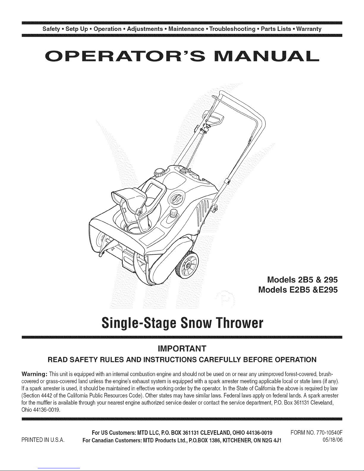
Models 2B5 & 295
Models E2B5 &E295
n le-StageSnowThrower
iMPORTANT
READ SAFETY RULES AND iNSTRUCTiONS CAREFULLY BEFORE OPERATION
Warning: Thisunitis equippedwithaninternalcombustionengineandshouldnotbeusedon or nearanyunimprovedforest-covered,brush-
coveredor grass-coveredlandunlesstheengine'sexhaustsystemisequippedwitha sparkarrestermeetingapplicablelocalor statelaws(if any).
If a sparkarresterisused,it shouldbemaintainedineffectiveworkingorderby theoperator.IntheStateof Californiathe aboveisrequiredbylaw
(Section4442ofthe CaliforniaPublicResourcesCode).Otherstatesmayhavesimilarlaws.Federallawsapplyonfederallands.A sparkarrester
forthe mufflerisavailablethroughyour nearestengineauthorizedservicedealeror contacttheservicedepartment,RO.Box361131Cleveland,
Ohio44136-0019.
FORMNO.770-10540F
05/18/06
PRINTEDIN U.S.A.
ForUSCustomers:MTDLLC,P.O.BOX361131CLEVELAND,OHiO44136-0019
ForCanadianCustomers:MTDProductsLtd.,P.O.BOX1386,KJTCHENER,ONN2G4J1
Page 2
This Operator's Manual is an important part of your new snow thrower, it will help you assemble,
prepare and maintain the unit for best performance. Please read and understand what it says.
Table of
Safety Labels ...................................................... 3
Safe Operation Practices ................................... 4
Setting Up Your Snow Thrower .......................... 6
Know Your Snow Thrower .................................. 7
Operating Your Snow Thrower ........................... 8
Finding and Recording Model Number
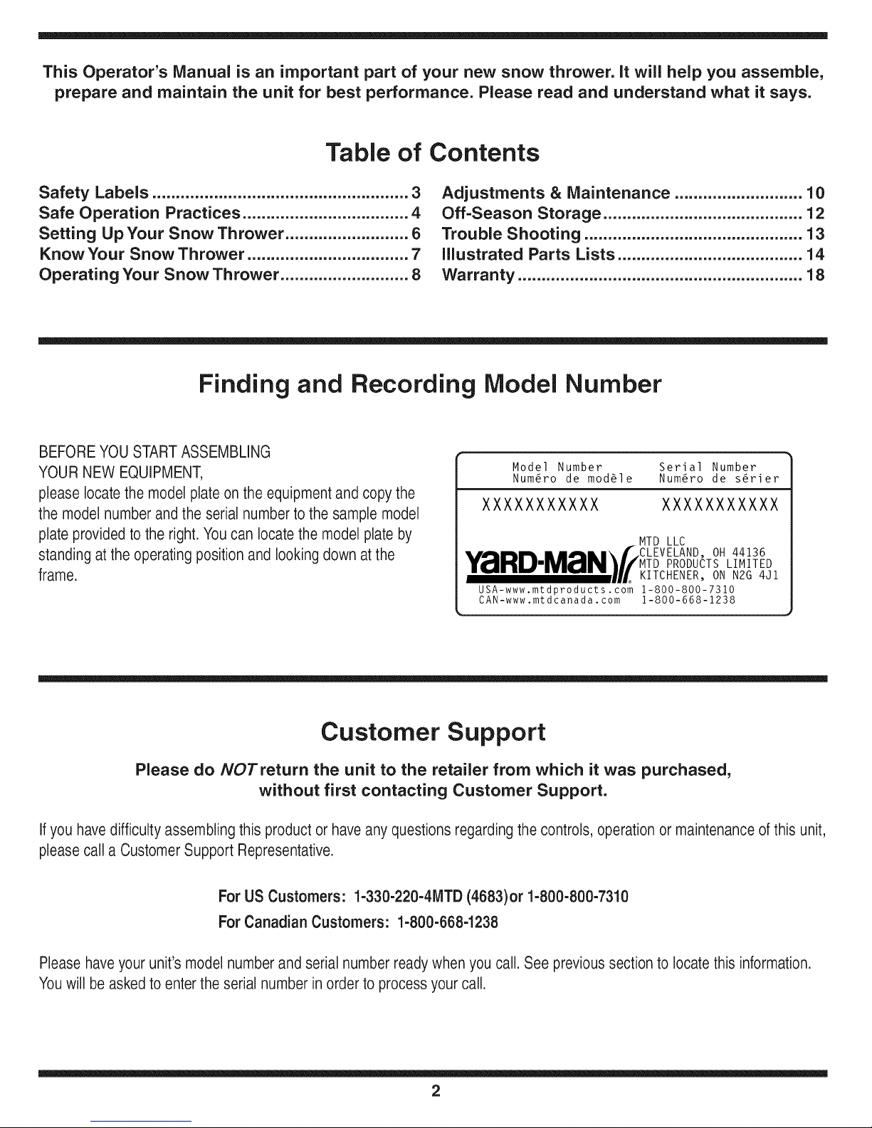
BEFOREYOU STARTASSEMBLING
YOURNEW EQUIPMENT,
please locatethe modelplate on the equipmentand copythe
the modelnumber andthe serial number to the sample model
plate provided to the right.You can locatethe model plate by
standing atthe operatingposition and looking down atthe
frame.
Contents
Adjustments & Maintenance ........................... 10
Off-Season Storage .......................................... 12
Trouble Shooting .............................................. 13
illustrated Parts Lists ....................................... 14
Warranty ............................................................ 18
Model Number Serial Number
Num6ro de mod61e Num6ro de s6rier
XXXXXXXXXXX XXXXXXXXXXX
•,,A .... m,,,.\f CLEVELAND, OH 44136
Y_IIHUIMZrIN_//MTD PRODUCTS LIMITED
........... UL KITCHENER, ON N2G 4Jl
USA-www.mtdproducts.com 1-800-800-7310
CAN-www.mtdcanada. com 1-800-668-1238
MTD LLC
Customer Support
Please do NOTretum the unit to the retailer from which it was purchased,
without first contacting Customer Support.
Ifyou havedifficultyassembling this productor haveany questionsregardingthecontrols, operationor maintenanceof this unit,
pleasecall a CustomerSupport Representative.
For US Customers: 1-330-220-4MTD (4683)or 1-800-800-7310
For Canadian Customers: 1-800-668-1238
Pleasehaveyour unit's modelnumber andserial number readywhenyou call. See previoussection to locate this information.
Youwill be asked to entertheserial number inorderto processyour call.
2
Page 3
i i l_I ii_ _ i _iii_!i _ _ii_ ii
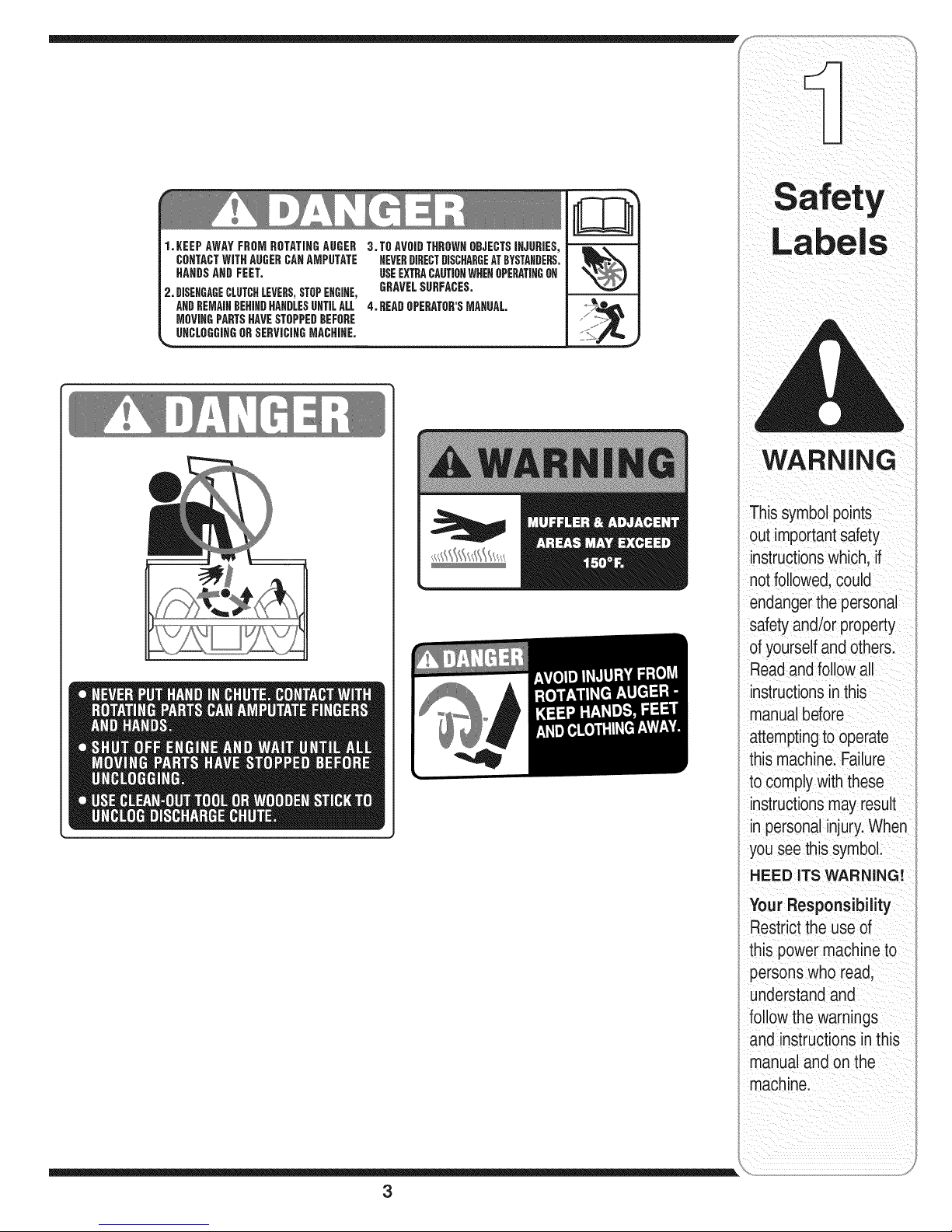
1.KEEPAWAYFROMROTATINGAUGER
CONTACTWiTHAUGERCAHAMPUTATE
HAHOSAND FEET.
2. DISEHGAGECLUTCHLEVERS,STOPEHGIHE,
ANDREMAINDEHIHDHAHBLESUNTILALL
MOVIHGPARTSHAVESTOPPEDBEFORE
UHCLOGGiHGORSERViCIHGMACHiHE.
3.TO AVOIDTHROWNOBJECTSIHJURIES,
NEVERDIRECTDISCHARGEATBYSTANDERS.
USEEXTRACAUTIONWHEHOPERATINGOH
GRAVELSURFACES.
4. BEADOPERATOR'SMAHUAL
WARNING
Thissymbolpoints
out importantsafety
instructionswhich,if
notfollowed,could
endangerthepersonal
safetyand/or property
ofyourselfandothers.
Readandfollowall
instructionsinthis
manualbefore
attemptingto operate
this machine.Failure
to complywiththese
instructionsmayresult
in personalinjury.When
youseethis symbol.
HEED ITS WARNING!
Your Responsibility
Restrictthe use of
this power machineto
personswho read,
understandand
followthe warnings
and instructionsin this
manualand onthe
machine.
3
Page 4
WARNING: EngineExhaust,some of itsconstituents,andcertain vehicle compo-
nentscontain or emitchemicals knownto State of Californiato causecancer and
birth defectsor otherreproductiveharm.
DANGER: This machinewas builtto beoperatedaccording to the rulesfor safe operationin this
manual.As with any type of power equipment,carelessnessor erroronthe part ofthe operatorcan
result inseriousinjury.This machine iscapableof amputatinghands andfeet andthrowing objects.
Failureto observethe followingsafety instructionscould resultinserious injuryor death.
WARNING
Thissymbolpoints
outimportantsafety
instructionswhich,ifnot
followed,could endanger
the personalsafetyand/
i or propertyofyourself
andothers. Readand
followall instructions
inthis manualbefore
attemptingtooperate
this machine.Failure
to complywiththese
instructionsmayresult
in personalinjury.When
youseethis symbol.
i HEED iTS WARNING!
Your Responsibility
i Restrictthe useof
this power machine
i to personswho read,
understandandfollow
the warnings and
instructionsin this
manualand on
the machine.
Training
1. Read,understand,andfollowallinstructionsonthe 1.
machineandin themanual(s)beforeattemptingto
assembleand operate.Keepthis manualinasafe place
forfutureand regularreferenceandfor ordering
replacementparts. 2.
2. Befamiliarwithall controlsandtheir properoperation.
Knowhowto stopthemachineanddisengagethem quickly.
3. Neverallowchildrenunder14yearsoldto operatethis
machine.Children14yearsoldandovershouldread
andunderstandtheoperationinstructionsandsafety 3.
rulesin thismanualandshouldbetrainedandsupervised
bya parent.
4. Neverallowadultsto operatethis machinewithout
properinstruction.
5. Thrownobjectscancauseseriouspersonalinjury.Plan 4.
yoursnow-throwingpatternto avoiddischargeof material
towardroads,bystandersandthe like.
6. Keepbystanders,helpers,petsandchildrenatleast75feet 5.
fromthe machinewhileit isin operation.Stopmachineif
anyoneentersthearea. 6.
7. Exercisecautiontoavoidslippingor falling,especially 7.
whenoperatingin reverse.
Preparation
Thoroughlyinspecttheareawheretheequipmentisto be
used.Removealldoormats,newspapers,sleds,boards,
wiresand otherforeignobjects,whichcouldbetripped over
orthrownbythe auger/impeller.
Alwayswearsafetyglassesor eyeshieldsduringoperation
andwhile performinganadjustmentorrepairto protectyour
eyes.Thrownobjectswhichricochetcancause serious
injurytothe eyes.
Do notoperatewithoutwearingadequatewinterouter
garments.Donotwearjewelry,longscarvesorother
looseclothing,whichcould becomeentangledin moving
parts.Wearfootwearwhich willimprovefootingon
slipperysurfaces.
Useagroundedthree-wireextensioncordand receptacle
forall unitswithelectricstartengines.
Adjustcollectorhousingheighttocleargravelorcrushed
rocksurfaces.
Disengageallcontrolleversbeforestartingthe engine.
Neverattemptto makeanyadjustmentswhileengineis
running,exceptwherespecificallyrecommendedinthe
operator'smanual.
8,
Letengineandmachineadjusttooutdoortemperature
beforestartingtoclearsnow.
9.
Toavoidpersonalinjuryorpropertydamageuse
extremecarein handlinggasoline.Gasolineis extremely
flammableand thevaporsare explosive.Seriouspersonal
injurycanoccurwhengasolineis spilledon yourselfor
yourclothes,whichcanignite.Washyourskin andchange
clothesimmediately.
a. Useonlyan approvedgasolinecontainer.
b. Extinguishallcigarettes,cigars,pipesandothersources
ofignition.
c. Neverfuelmachineindoors.
d. Neverremovegascap oraddfuelwhilethe engineis
hotor running.
e. Allowengineto coolat leasttwo minutesbefore
refueling.
f. Neveroverfill fueltank. Filltankto nomorethan
Y2inchbelowbottomoffiller neckto providespace
forfuel expansion.
g. Replacegasolinecap andtightensecurely.
h. If gasolineis spilled,wipeitoff theengineand
equipment.Movemachineto anotherarea.Wait5
minutesbeforestartingthe engine.
i. Neverstorethe machineorfuel containerinsidewhere
there isan openflame, sparkor pilot light(e.g.furnace,
waterheater,spaceheater,clothesdryeretc.).
j. Allowmachinetocoolat least5 minutesbeforestoring.
4
Page 5
Operation
1. Do notput handsor feet nearrotatingparts,inthe
auger/impellerhousingorchuteassembly.Contactwiththe
rotatingpartscanamputatehandsand feet.
2. Theauger/impellercontrolleveris a safetydevice.Never
bypassits operation.Doingso makesthemachineunsafe
andmaycausepersonalinjury.
3. Thecontrolleversmustoperateeasilyin bothdirections
andautomaticallyreturntothe disengagedpositionwhen
released.
4. Neveroperatewithamissingordamagedchuteassembly.
Keepallsafetydevicesinplaceandworking.
5. Neverrunanengineindoorsor ina poorlyventilatedarea.
Engineexhaustcontainscarbonmonoxide,an odorlessand
deadlygas.
6. Do notoperatemachinewhileunderthe influenceofalcohol
or drugs.
7. Mufflerandenginebecomehotandcan causea burn.Do
nottouch.
8. Exerciseextremecautionwhenoperatingonor crossing
gravelsurfaces.Stayalertfor hiddenhazardsortraffic.
9. Exercisecautionwhenchangingdirectionandwhile
operatingon slopes.
10.Planyoursnow-throwingpatternto avoiddischargetowards
windows,walls,carsetc.Thus,avoidingpossibleproperty
damageor personalinjurycausedbyaricochet.
11.Neverdirectdischargeatchildren,bystandersandpetsor
allowanyoneinfront of the machine.
12.Donotoverloadmachinecapacityby attemptingtoclear
snowattoofastof a rate.
13.Neveroperatethis machinewithoutgoodvisibilityor light.
Alwaysbe sureofyourfootingand keepafirmhold onthe
handles.Walk,neverrun.
14.Disengagepowerto theauger/impellerwhentransporting
or not inuse.
15.Neveroperatemachineathightransportspeedsonslippery
surfaces.Lookdownand behindandusecarewhen
backingup.
16.Ifthe machineshouldstarttovibrateabnormally,stopthe
engine,disconnectthespark plugwireandgroundit against
the engine.Inspectthoroughlyfor damage.Repairany
damagebeforestartingandoperating.
17.Disengageallcontrolleversand stopenginebeforeyou
leavetheoperatingposition(behindthe handles).Wait
untilthe auger/impellercomestoa completestopbefore
uncloggingthechuteassembly,makinganyadjustments,or
inspections.
18.Neverput yourhandinthe dischargeorcollectoropenings.
Alwaysuse theclean-outtool providedto unclogthe
dischargeopening.Do notunclogchuteassemblywhile
engineis running.Shutoffengineand remainbehind
handlesuntilallmovingparts havestoppedbefore
unclogging.
19.Useonlyattachmentsandaccessoriesapprovedbythe
manufacturer(e.g.wheelweights,tirechains,cabsetc.).
20. Ifsituationsoccurwhicharenotcoveredinthis manual,
usecareand goodjudgment.Contactyourdealerorcall
(800) 800-7310for assistanceandthenameof yournearest
servicingdealer..
Maintenance & Storage
1. Nevertamperwithsafetydevices.Checktheir proper
operationregularly.Refertothe maintenanceand
adjustmentsectionsofthismanual.
2. Beforecleaning,repairing,orinspectingmachine
disengageall controlleversandstopthe engine.Wait until
theauger/impellercometo acompletestop.Disconnectthe
sparkplugwireandgroundagainsttheengineto prevent
unintendedstarting.
3. Checkbolts andscrewsforpropertightnessatfrequent
intervalstokeepthe machinein safeworkingcondition.
Also,visuallyinspectmachinefor anydamage.
4. Do notchangethe enginegovernorsettingorover-speed
theengine.The governorcontrolsthemaximumsafe
operatingspeedoftheengine.
5. Snowthrowershaveplatesandskidshoesaresubjectto
wearanddamage.Foryoursafetyprotection,frequently
checkallcomponentsandreplacewith originalequipment
manufacturer's(OEM)partsonly."Useof partswhich do
notmeetthe originalequipmentspecificationsmayleadto
improperperformanceandcompromisesafety!"
6. Checkcontrolsperiodicallytoverify theyengageand
disengageproperlyandadjust,if necessary.Referto the
adjustmentsection inthisoperator'smanualforinstructions.
7. Maintainor replacesafetyandinstructionlabels,as
necessary.
8. Observeproperdisposallawsandregulationsfor gas,oil,
etc.toprotectthe environment.
9. Priorto storing,runmachineafew minutestoclearsnow
frommachineandpreventfreezeupof auger/impeller.
10.Neverstorethemachineorfuel containerinsidewhere
thereisan openflame,sparkor pilotlightsuchasa water
heater,furnace, clothesdryeretc.
11.Alwaysreferto theoperator'smanualforproperinstructions
onoff-seasonstorage.
Do not modify engine
Toavoidseriousinjuryordeath,donot modifyengineinany
way.Tamperingwiththegovernorsettingcan leadto a runaway
engineandcauseit to operateatunsafespeeds.Nevertamper
withfactorysettingofenginegovernor.
Notice regarding Emissions
Engineswhicharecertifiedto complywithCaliforniaandfederal
EPAemissionregulationsforSORE(SmallOff RoadEquipment)
arecertifiedto operateonregularunleadedgasoline,and
mayincludethefollowingemissioncontrolsystems:Engine
Modification(EM)andThreeWayCatalyst(TWO)ifsoequipped.
Your Responsibility
Restrictthe useofthis powermachineto personswhoread,
understandandfollowthewarningsandinstructionsinthis
manualandonthe machine.
WARNING
Thissymbolpoints
outimportantsafety
instructionswhich,ifnot
followed,couldendanger
the personalsafetyand/
orpropertyof yourself
and others.Readand
followall instructions
in this manualbefore
attemptingtooperate
this machine.Failure
to complywiththese
instructionsmayresult
in personalinjury.When
youseethissymbol.
HEED iTS WARNING!
Your Responsibility
Restrictthe use of
this power machine
to personswho read,
understandand follow
the warnings and
instructions inthis
manualand on
the machine.
5
Page 6
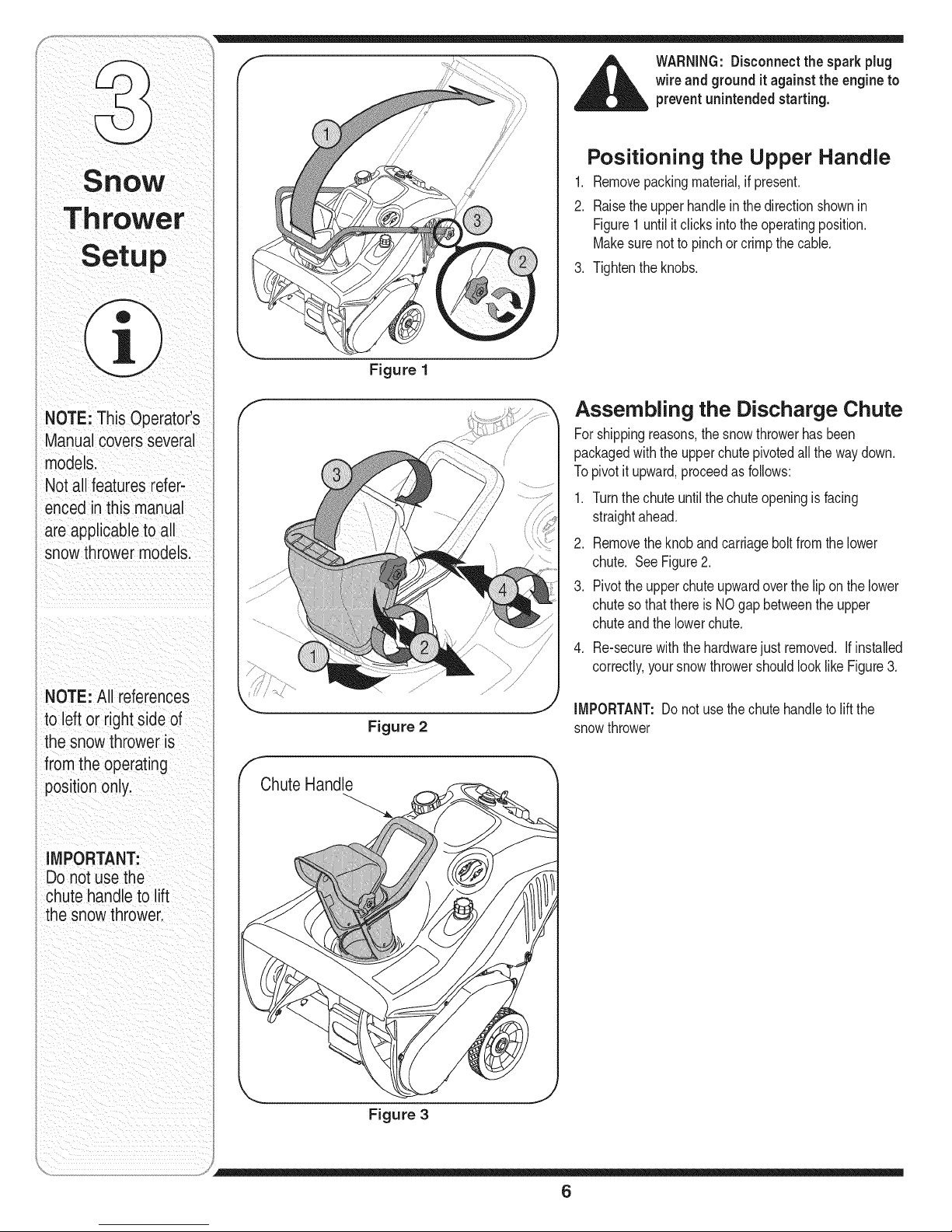
Figure 1
Positioning the Upper Handle
1. Removepackingmaterial,ifpresent.
2. Raisethe upperhandleinthedirectionshownin
Figure1 untilitclicksintotheoperatingposition.
Makesurenottopinchor crimpthecable.
3. Tightenthe knobs.
NOTE:This Operator's
Manualcoversseveral
models.
Notall features refer-
encedinthis manual
are applicableto all
snow throwermodels.
I NOTE: All references
i to leftor rightside of
the snowthrower is
fromthe operating
I positiononly.
i IMPORTANT:
i Donot use the
chute handleto lift
thesnow thrower.
f
Chute Handle
Figure 2
Assembling the Discharge Chute
Forshippingreasons,thesnowthrowerhasbeen
packagedwiththe upperchutepivotedall thewaydown.
Topivotit upward,proceedasfollows:
1. Turnthechuteuntilthechuteopeningis facing
straightahead.
2. Removetheknob andcarriageboltfromthelower
chute. SeeFigure2.
3. Pivotthe upperchuteupwardovertheliponthelower
chutesothatthere isNOgap betweentheupper
chuteandthelowerchute.
4. Re-securewiththe hardwarejust removed. If installed
correctly,yoursnowthrowershouldlooklike Figure3.
IMPORTANT:Do notusethechutehandleto liftthe
snowthrower
Figure 3
6
Page 7

Recoil Starter
Primer
GasolineCap Button (if equipped)
ChuteAssembly_
ShavePlate Spark PlugAccess
Auger
Figure 4
Choke Lever
Activatingchokecontrolclosesthechokeplateon
carburetorandaids in startingengine.Refertotheengine
manualpackedwithunitformoredetailedinstructions.
Primer
Depressingprimerforcesfueldirectlyintoengine's
carburetorto aid incold-weatherstarting.Refertoengine
manualpackedwithunitformoredetailedinstructions.
Ignition Key
Theignitionkeymustbeinsertedandsnappedin place
in orderforthe engineto start.Removetheignitionkeyto
preventunauthorizeduseofequipment.DoNOTattempt
toturn thekey.
Recoil Starter
Thestarterhandleisusedtomanuallystarttheengine.
Electric Starter (if Equipped)
Usedtostartenginewitha 120Vpowersource.
Plug for Electric Start
Requiresuseofa three-prongoutdoorextensioncord
anda 120Vpowersource.
Spark Plug Cover
Removesparkplugcovertoaccesssparkplug.
Oil Fill
Auger
Whenengaged,the augersrotationdrawssnowinto the
augerhousingandthrowsitout thedischargechute.
Rubberpaddleson the augersalsoaidin propellingthe
unitas theycomeincontactwiththe pavement.
Auger Control Handle
Locatedon the upperhandle,theaugercontrolhandle
isusedtoengageanddisengagedriveto theauger.
Squeezethecontrolhandleagainsttheupperhandleto
engageauger;releaseitto disengage.
Discharge Chute / Chute Handle
Rotatethedischargechuteto theleftor rightusing
chutehandle.Theangleofthe dischargechutecontrols
thedistancethatthesnowis thrown.Tiltthe discharge
chuteupforgreaterdistance;tiltdownfor lessdistance.
Loosenthehandknobonthe sideof thedischarge
chutetoadjust.Tilt thechuteto thedesiredposition,
andtightentheknob.
Shave Plate
Theshaveplatemaintainscontactwithpavementas
thesnowthroweris propelled,allowingsnowcloseto
pavement'ssurfaceto bedischarged.
WARNING
Be familiar with
allthe controls on
tahesnowthrower
ndtheir proper
operation. Knowhow
to stop the machine
anddisengage them
quickly.
7
Page 8

Before Starting
1. Thesparkplugwirewasdisconnectedforsafety.
Attachsparkplugwireto sparkplugbeforestarting.
IMPORTANT:Forcompleteanddetailedengine
starting,stoppingand storinginstructions,it is
recommendedthatyoureadthe enginemanualalso
includedwiththis unit.
Gas and Oil Fill-Up
1. Checkoilandgasolinelevelandadd ifnecessary.
Followrelatedinstructionsinthe separateengine
manualpackedwithyoursnowthrower.
f
_,ugerControlHandle
RecoilStarter
Primer
Gasoline_
Cap
\
Key
Ele( Starter |
Button if equipped)l
WARNING
Read, understand,
and follow all instruc-
tions and warnings
onthe machine and
in this manual before
operating.
Use extreme care
when handling
gasoline. Gasoline is
extremely flammable
and the vapors are
i explosive. Neverfuel
the machine indoors
or while the engine
i is hot or running.
i Extinguish cigarettes,
cigars,pipes and
other sources of
ignition.
The electric starter
must be used with a
properly grounded
three-prong
receptacle at all
times to avoid the
i possibilityof electric
i shock. Follow all
i instructionscarefully
prior to operating the
electric starter.
_ ARNING:Useextremecarewhen
handlinggasoline. Gasolineis
extremely flammableand the vapors
are explosive. Neverfuel the machine
indoorsor while the engineis hot or
running.Extinguish cigarettes, cigars,
pipesand other sources of ignition.
To Start Engine
1. Insertignitionkeyintoslot.
2. Nowfollowthe instructionsbelowasitpertainsto
yourunit.SeeFigure4forlocationof controls
Electric Starter (if so equipped)
WARNING:Theelectricstartermust
be usedwitha properly groundedthree-prong receptacleat all times to
avoidthe possibilityof electric shock.
Follow all instructionscarefullyprior
to operating the electric starter.
1. Theelectricstarterisequippedwitha grounded
three-wirepowercordandplug,andisdesignedto
operateon120voltAC householdcurrent.
2. Determinethatyour housewiringisa three-wire
groundedsystem.Aska licensedelectricianif you
arenotcertain.
3. If your home wiringsystem isnot a three-wire
grounded system, do notusethiselectricstarter
underanyconditions.
4. If your home electricalsystemisgrounded, but
a three-holereceptacleis notavailable,oneshould
beinstalledbya licensedelectricianbeforeusingthe
electricstarter.
5. If you have a grounded three-prong receptacle,
proceedasfollows:
6. MoveChokeControlto "Full"position.
7. Pushprimerslowly,three(3) times,makingsureto
coverventholewhenpushing.
8. Connectpowercordtoswitchboxondashpanel.
Plugtheotherendof powercordintoa three-prong
120-volt,grounded,ACreceptacle.
Cap Plug j)
Figure 5
9. Pushstarterbuttonto crankengine.Asyoucrankthe
engine,movechokeleverto FULLchokeposition.
10.Whenenginestarts,releasestarterbutton,andmove
chokegraduallytoOFRif enginefalters,movechoke
immediatelyto FULLandthengraduallytoOFR
11.Whendisconnectingthepowercord,alwaysunplug
from thethree-prong receptaclefirst, and then
from thesnow thrower.
Recoil Starter
1. Movechokeleverto FULLchokeposition(coldengine
start).
2. If engineiswarm,placechokeinOFFpositioninstead
ofFULL.
3. Pushprimerbuttonslowlytwoorthreetimes forcold
enginestart.
4. If engineiswarm,pushprimerbuttononlyonce.
NOTE:Alwayscoverventholein primerbuttonwhen
pushing.Additionalprimingmaybe necessaryforfirst
startif temperatureisbelow150F(-90C).
5. Graspstarterhandleandpullropeout slowly,untilit
pullsslightlyharder.Letroperewindslowly.
6. Pullstarterhandlerapidly.Donotallowhandleto snap
back.Allowitto rewindslowlywhilekeepinga firm
holdonthestarterhandle.
7. As enginewarmsupandbeginstooperateevenly,
rotatechokeleverslowlytoOFFposition.If engine
falters,returnto FULLchoke,thenslowlymoveto OFF
position.
8
Page 9

To Stop Engine Operating Tips
1. To stopengine,turnignitionkeycounter-clockwise.
Disconnectthesparkplugwirefromthesparkplug
to preventaccidentalstartingwhileequipmentis
unattended.
Tohelppreventpossiblefreeze-upof starter,
proceedas follows:
1. Runengineforafew minutesbeforestoppingtohelp
dryoff anymoistureonthe engine.
2. Electric Starter (optional}: Connectpowercordto
switchboxon engine,thento 120voltACreceptacle.
Withtheenginerunning,pushstarterbuttonandspin
thestarterforseveralseconds.Theunusualsound
madeby spinningthestarterwill notharmengineor
starter.Disconnectthepowercordfrom receptacle
first,andthenfromswitchbox.
3. RecoilStarter: Withenginerunning,pullstarterrope
witha rapid,continuousfullarmstrokethreeorfour
times.Pullingthestarterropewillproducea loudclatter-
ingsound,whichisnotharmfultotheengineorstarter.
4. Wipeall snowand moisturefromthe carburetorcover
intheareaof thecontrollevers.Also,movecontrol
leversbackandforthseveraltimes.Leavechoke
controlintheFULLchokeposition.
5. Removeignitionkeyanddisconnectsparkplugwireto
preventaccidentalstarting.
1. Dischargesnowdownwindwheneverpossible.
Slightlyoverlapeachpreviouslyclearedpath.
2. Liftinguponthe handlewillallowthe rubberon the
augersto propelthesnowthrowerforward.Pushing
downwardon the handlewillraisetheaugersoffthe
groundandstopforwardmotion.
NOTE:Excessiveupwardpressureon the handlewill
resultinprematurewearontherubberaugerblades
whichwouldnot becoveredbywarranty.
3. Runtheenginefor a fewminutesbeforestoppingto
helpdryanymoistureonthe engine.
4. Cleanthesnowthrowerthoroughlyaftereachuse.
WARNING
Muffler,engineand
surroundingareas
become hot and
causeaburn:
Do not touch,
Operating the Snow Thrower
Thepitchof thechuteassemblycontrolstheangleat
whichthesnowisthrown.Adjustthe chuteassemblyby
followingtheinstructionsbelow.
1. Loosenthewing knobfoundontheleftsideof the
chuteassemblyandpivotthe upperchuteupwardor
downwardto thedesiredpitch.Retightenthe wing
knobbeforeoperatingthesnowthrower.
2. Positionthechuteassemblyopeningby usingthe
ChuteHandletothrowthe snowinthedesireddirec-
tion.See Figure6.
.._ J
Figure 6
IMPORTANT:
Forcomplete and
detailed engine
starting, stoppingand
storing instructions,
it isrecommended
that you read the
_=nginemanual also
includedwith
this unit.
NOTE:
Excessiveupward
pressure on the
handlewillresult in
premature wear
on the rubber
auger blades which
would not be covered
by warranty.
9
Page 10

MaintenanCe
WARNING
Disconnect the
spark plugwire
and ground it against
the engine to prevent
unintended starting.
NEVERattempt
to make any
adjustments while
I the engine is
running, except
where specified in
the operator's
manual.
Before servicing,
repairing, or
inspecting,
disengage the
control bail and
stop engine. Wait
i until all moving
i parts havecome to a
complete stop.
_ ARNING:NEVERattemptto make
any adjustments whilethe engineis
running,exceptwherespecified inthe
operator'smanual.
Figure 7
/
Figure 8
Shave Plate
1. Tocheckthe adjustmentofthe shaveplate,placethe
uniton a levelsurface.Thewheels,shaveplateand
augersshouldallcontactlevelsurface.Notethatif the
shaveplateis adjustedtoohigh,snowmayblowunder
thehousing.Ifthe shaveplatewearsout excessively,
ortheunit doesnot self-propel,theshaveplatemay
betoolowand needsto beadjusted.
NOTE:On newunitsorunitswitha newshaveplate
installed,theaugersmaybeslightlyoff theground.
2. Toadjust,tip thesnowthrowerbacksothat it restson
thehandle.Loosenthefourlocknutsand boltswhich
securetheshaveplatetothe housing.See Figure7.
Movetheshaveplatetodesiredpositionand retighten
thenutsandboltssecurely.
Replacing Shave Plate
Theshaveplate isattachedtothe bottomof theauger
housingandis subjecttowear.It shouldbechecked
periodically.Therearetwo wearingedgesandthe shave
platecan bereversed.RefertoFigure7.Toreplaceor
reversethe shaveplateproceedasfollows.
,
Removethecarriageboltsand hexlocknutswhich
attachit tothe snowthrowerhousing.
2.
Installnewshaveplate(or reverse),makingsurethe
headsof thecarriageboltsare ontheinsideofthe
housing.
,
Adjusttheshaveplateaccordingto instructionsabove
4. Tightensecurely.
Control Cable
Asa resultof boththecontrolcableandthedrive belt
stretchingdueto wear,periodicadjustmentsmaybe
necessary.
If theaugerseemsto hesitatewhenrotatingwhilethe
enginemaintainsa constantspeed,an adjustmentis
necessary.Proceedasfollows:
Theupperholeinthe controlhandleprovidesfor an
adjustmentincabletension.Toadjust,disconnectthe
endofcontrolcablefromthebottomholeinthecontrol
handleand reinsertit intheupperhole.Insertthecable
fromtheoutsideas shownin Figure8.Testthe snow
throwerto seeif thereisa noticeabledifference.
Carburetor
,__ WARNING:If any adjustments needto
be madeto the enginewhile the engine
isrunning(e.g. carburetor), keep
clear of all moving parts.Becareful of
muffler, engine and other surrounding
heatedsurfaces.
1. Referto theseparateenginemanual,packedwith
yourunit,for carburetoradjustmentinformation.
10
Page 11

Replacing Belt
_il ARNING:Before servicing,repairing,
Removethebeltcoverbyremovingfivehexscrews.See
Figure9.Thensimplypullthebeltoff bygraspingitfrom
thebottomofthe augerpulleyandpullingoff. Onceyou
removethe beltfromthe pulleys,youcanpushdownon
theidlerpulleytoreleasethebelt fromunderbeltkeeper.
Toreplacethebeltfollowtheseinstructionsandreferto
Figure10:
1. Pushdownon theIdlerpulley.
2. Putbelton top oftheaugerpulleyunderbeltkeeper.
3. Threadbeltaroundenginepulley.
4. Pushbeltoverbottomof augerpulley.
Reinstallthebelt coverremovedearlier.
or inspecting,disengagethe control
bail and stop engine.Waituntil all
moving partshavecome to a complete
stop. Disconnect spark plug wire and
ground itagainst the engine to prevent
unintended starting.
Engine
1. Referto theseparateenginemanualforaNengine
maintenanceprocedures.
2. Checkengineand snowthrowerfrequentlyforloose
hardware,andtightenas needed.
Lubrication
Lubricatepivotpointsonthe controlhandleandthe
extensionspringatthe endofthe controlcable witha
lightoilonce everyseasonandbeforestorageofthe
snowthrowerat theendof theseason.
Replacing Auger Paddies
Thesnowthrowerauger'srubberpaddlesaresubjectto
wearandshouldbe replacedifanysignsof excessive
wearis present.
IMPORTANT:DoNOTallowtheauger'srubberpaddles
towearto the pointwhereportionsofthemetalauger
itselfcancomeincontactwiththepavement.Doingso
canresultinseriousdamagetoyour snowthrower.
Tochangetherubberpaddles,proceedasfollows:
1. Removethe existingrubberpaddlesbyunthreadingthe
self-tappingscrewswhichsecurethemtotheauger.
SeeFigure11.
2. Securethereplacementrubberpaddlestothe auger
usingthe hardwareremovedearlier.
Figure 9
\
Figure 10
/
/ /
Maintenance
Before servicing,
repairing,or nspect,
ing, disengage the
controlbailandstop
engine; Wait until
moving parts have
i
/
come to a complete
stop;Disconnect
and
ground it against the
engine tO prevent
unintended starting:
IMPORTANT:DONOT
allow the augerlsrubber
paddles to weartothepoint
wheie portio0softhemetal
auger itselfcan Comein
contact withthepavement.
Doing SOCanresultin
serious damagetOyour
Figure 11
11
Page 12

WARNING
Never store snow
i thrower with fuel
in tank indoorsor
in poorly ventilated
areas, where fuel
fumes may reach an
open flame, spark
or pilot light as on a
furnace, water heater,
i clothes dryer or gas
, appliance.
Drain fuel intoan
approved container
outdoors,away from
any open flame. Be
certain engine is
i cool. Do not smoke.
Fuel left in engine
during warm weather
deteriorates and
will cause serious
starting problems.
Observethe following,whenpreparingyour snow
throwerfor off-seasonstorage:
• Drainfuelintoanapprovedcontaineroutdoors,away
fromanyopenflame.Allowengineto cool.Extin-
guishcigarettes,cigars,pipesandother sources
ofignitionpriortodrainingfuel. Fuelleft inengine
duringwarmweatherdeterioratesandwillcause
seriousstartingproblems.
If unitis tobestoredover30 days,preparefor
storageasinstructedinthe separateenginemanual
packedwithyourunit.
Runengineuntilfueltankis emptyandenginestops
duetolackof fuel.
Removegasolinefromcarburetorandfuel tankto
preventgum depositsfromformingontheseparts
andcausingpossiblemalfunctionof engine.
Draincarburetorbypressingupwardon bowldrain,
locatedbelowthecarburetorcover.
• Fuelstabilizers,suchasSTA-BIL®,areanaccept-
ablealternativein minimizingtheformationoffuel
gumdepositsduringstorage.Donotdraincarburetor
ifusinga fuelstabilizer.
• Wipeequipmentwithanoiled ragto preventrust.
• Removesparkplugandpouroneounceofengine
oilthroughsparkplugholeinto cylinder.Coverspark
plugholewithrag.Crankengineseveraltimesto
distributeoil.Replacesparkplug.
• Followthelubricationrecommendationsfoundinthe
MaintenanceSection.
Alwaysstorethe snowthrowerina clean,dryarea.
Do not drain
carburetor if using
fuel stabilizer.
Never use engine or
carburetor cleaning
i products inthe fuel
tank or permanent
damage may occur.
12
Page 13

Problem Cause Remedy
Fn_ n_fn _tn _tnd [ 11 ChOkenotinON position: 1 MoveChoketo ONposton
_-= " " "!" "" Sparkplugwiredisconnected. 2: Connectwlreto sparkplug.
Fue!tankemptyor stalefuel. &Fill tankwithcleanlfreShgaSoiinel
4 Enginenotprimed. ,Primeengineas instructedin
op ia,ngYouiSniwTh!o ei
5 FaultySparkplug Clean;adjustgap,or replace:
61Blocked fuellinei 6. Cleanfuel !inel
safetykeynotin ignitiononengine, 7 !nser!keyfu! Yint° ,heswitch:
8. Fue Shut-offvave cosed.(f 8. Openrue shut-df vare:
Engineruns erratic
1. UnitrunningonCHOKE.
2. Blockedfuellineor stalefuel.
3. Wateror dirtin fuelsystem.
4. Carburetoroutof adjustment.
1. Movechokeleverto OFFposition.
2. Cleanfuelline; filltankwithclean,
freshgasoline.
3. Drainfueltank. Refillwith
freshfuel.
4. ContactServiceCenter.
Engne overheats 1 Carburetornotadjustedpropery 1 ContactServce Center
Excessive 1. Loosepartsor damagedauger. 1. Stopengineimmediatelyand
Vibration disconnectsparkplugwire.Tighten
all boltsand nuts.Ifvibration
continues,haveunitservicedbya
ServiceCenter.
Lossof power 1, Sparkplugwire loose. 1. Connectandtightensparkplug
wire.
2. Gas capventholeplugged. 2. Removeice andsnowfromgas
I cap.Becertanventholeisclear.
• 3 Exhaustportplugged ". 3 ContactServiceCenter
NOTEi ThiSsection
addressesminor
service issues: For
further details,contact
customerassistancel
ii i _iI_ ii
Unit fails 1. Drivecontrolcane in needof adjust- 1. Adjustdrivecontrolcane. Referto
to propelitself merit. "Adjustments".
2. Drivebelt looseordamaged. 2. Replacedrivebelt.
Unit fails 1, Chuteassemblyclogged. 1. Stopengineimmediatelyand
to dscharge snow disconnectsparkplugwire.Clean
2. Foreignobjectlodgedinauger. 2, Stopengineimmediatelyand
3. Augerbeltlooseor damaged. 3, RefertoMaintenancesection
chuteassemblyandinsideof
augerhousingwithclean-outtool
ora stick.
disconnectsparkplugwire.
Removeobjectfromauger.
13
Page 14

iVlodel/iVlodele 2B5-295
NOTE:Snowthrowerfeatures/componentsvary bymodel.NOTall partslistedaboveandpicturedonthe previouspageare standardequipment.
REMARQUE:Lescaract_ristiques/composantsdessouffleusesvarientd'unmodule&unautre.Lespi_ces_num_r_esci-dessuset illustr_essurla
pagepr_c_dentenesontpas TOUTESfourniesen serie.
14
Page 15

Model/Modele 2B5-295
REF PART
NO, NO,
N° DE N° DE
RI_F PI_:CE
1 629-0071
2 710-0409
3 710-0627
4 710-0654A
5 710-0751
6 710-1003
7 712-04064
8 726-0154
9 726-0201
10 726-0205
11 731-2825
12 736-0119
13 736-0242
14 747-04236
15 750-04297B
16 751-0535
17 751-10023
18 751-10278
19 754-0101A
20 756-0416B
21 756-04232
22 790-00216
23 790-00134
24 7511152847
25 7512B1476
26 734-04225
27 684-04168
28 735-04033
29 710-0896
30 735-04032
31 684-04025A
32 710-0642
33 710-0653
34 712-0896
35 710-0352
36 712-04063
37 726-0299
38 736-0326
39 736-0329
40 736-0176
41 741-04188
42 684-04227
43 748-0234
44 738-0924A
45 790-00249
46 790-00283
47 790-00045A
48 710-0106
49 756-0625
50 684-04228
51 750-04571
52 722-3022
Extension Cord 10 Ft.
Hex Bolt 5/16-24 x 1.75
Hex L-Bolt 5/16-24 x .75 Gr. 5
Hex Wash HD Tap Scr 3/8-16 x .88
Hex Bolt 1/4-20 x .62 Gr. 5
Hex Wash B-Tapp Scr #10 x .62" Lg.
Hex L-Flanged Nut 1/4-20 Gr. F Nylon
Push Mount Tie
Push Speed Nut
Hose Clamp
Choke Knob
L-Wash 5/16 ID
Flat Washer .340 ID x .872 OD x .060
Gas Tank Wire Support
Spacer .875 x .320 x 1.10
Fuel Line
Fuel Tank 2 Quart
Cap-Fuel
V-Belt 1/2 x 35.0" Lg.
Pulley Half .625 ID x 2.25 OD
Pulley 1/2 x 6,0" OD
Engine Bracket
Gas Tank Support Bracket
Primer Hose Line
Primer
Wheel, 7.0 x 1.5 Lug
Idler Pulley (1/4" hole)
Rubber Paddle
Hex B-Tap Scr 1/4-28 x .25" Lg
Rubber Spiral-Crescent
Auger Ass'y 21" w/Solid Shaft
Thd Forming Scr. 1/4-20 x .75 Lg.
Hex Wash HD Tapp Scr 1/4-20 x .375
Hex Ins Jam L-Nut 1/4-28
Hex Tap Scr. 1/4-14 x .375" Lg.
Flange Locknut 5/16-18 Gr. F, Nylon
Push Cap x 1/2" Rod
Flat Washer .50 ID x 1.00 OD x .125
L-Wash 1/4 ID
Flat Washer .25 ID x .93 OD x .125
Ball Bearing .625 x 37 x 12.63
Auger Assembly Housing
Shoulder Spacer .25 THK
Hex Shld.Scr.1/4-28 x .375
Bearing Cup
Idler Bracket
Belt Cover
Hex Screw 1/4-20 x 1.25 Gr. 5 Special
Cable Guide Roller
Auger Assembly
Shld. Spacer .260 x .785 x .538
Tape
DESCRIPTION
DESCRIPTION
Corde a ralonge de 10 pi de Ig.
Boulon hex. 5/16-24 x 1,75
Boulon hex 5/16-24 x 0,75 Qual. 5
Vis autotaraudee 3/8-16 x 0,88
Boulon hexagonale 1/4-20 x 0,62 Qual. 5
Vis taraud6e nO. 10 x 0,62 po de Ig.
Contre-ecrou a embase 1/4-20 Qual. F nylon
Tige de poussoir
Ecrou rapide d'enfoncer
Collier
Manette de volet de d6part
Rondelle frein 5/16 DI
Rondelle plate 0,340 DI x 0,872 DE x 0,060
Fil de support - reservoir a carburant
Entretoise 0,875 x 0,320 x 1,10
Ligne d'essence
R6servoir de carburant de 2 quarts
Capuchon d'essence
Courroie trapezdidale 1/2 x 35,0 po de Ig
Moitie poulie 0,625 DI x 2,25 DE
Poulie 1/2 x 6,0" DE
Support du moteur
Support de reservoir de carburant
Ligne d'amorgeur
Amor_:eur
Roue, 7,0 x 1,50 Lug
Poulie du tendeur (trou 1/4 po)
Pale en caoutchouc
Vis taraud6e a t_te hexagonale 1/4-28 x 0,25
Spirale en caoutchouc - croissant
Ens. de la tariere de 21 po avec arbre solide
Vis taraud6e 1/4-20 x 0,75 Ig.
Vis auto-taraudeuse hexagonale 1/4-20 x 0,375
Contre-6crou de blocage 1/4-28
Vis taraud6e 1/4-14 x 0,375 po de Ig.
Contre-ecrou a embase 5/16-18 Qual. F, nylon
l_crou pour tige de 1/2 po
Rondelle plate 0,50 DI x 1,0 DE x 0,125
Rondelle frein 1/4 DI
Rondelle plate 0,25 DI x 0,93 DE x 0,125
Roulement a billes 0,625 x 37,0 x 12,63
Logement de la tariere
Entretoise epaul6e
Visa epaulement 1/4-28 x 0,375
Roulement a cuvette
Support du tendeur
Couvercle de courroie
Visa t_te hex. 1/4-20 x 1,25 Qual. 5 Special
Guide du c&ble
Ensemble de la tariere
Entretoise 0,260 x 0,785 x 0,538
Bande
31A-2951
5.18.06
Forparts and/or
accessories refer to
customer support on
page2.
Adressez-vousau
,,Service apr_s-vente>,
la page 2 pource qui
-oncerne les pi_ces
et/ou accessoires.
NOTE:Fora properworkingmachine,useFactoryApprovedParts.V-beltsaredesignedtoengageanddisen-
gagesafely.A substitute(nonOEM)V-beltcanbe dangerousbynotdisengagingcompletely.
REMARQUE:N'utilisezquedescourroieshomologu_esparI'usine. Lescourroiestrap_zdldalessontcon_ues
pourunembrayageet und_brayagesansdanger.Eemploid'unecourroiederemplacement(sansI'_tiquette
d'_quipementd'origine)peuts'avererdangereuxsi cettecourroienesed_brayepascompl_tement.
15
Page 16

iVlodel/iVlodele 2B5-295
_11)
16
Page 17

REF PART
NO. NO.
N° DE N° DE
R#:F PIt_CE
1 684-04127
2 710-04071
3 710-0451
4 712-04063
6 731-04388A
7 731-04354A
9 710-04532
10 720-04072
11 725-0157
13 747-04159
14 749-04106
15 684-0178
16 684-04032
684-04029
684-04211
684-04030
17 710-0895
18 710-1003
19 710-1090
20 710-1882
21 710-3083
22 712-0252
23 725-2018
24 736-0225
25 736-0400
26 736-0451
27 7510009636
28 710-0134
29 710-3008
30 712-04064
31 731-1033
32 736-0176
33 746-04237
34 749-04114
35 725-0201
36 684-0190
37 731-04127
38 731-04353
39 731-04886
40 732-04111
41 732-0357A
DESCRIPTION
Lower Chute Ass'y (Incl. #37-40)
Carriage Screw 5/16-18 x 1.0
Carriage Bolt 5/16-18 x .75
Flange Locknut 5/16-18 Gr. F, Nylon
Chute Handle
Upper Chute
Carriage Bolt 5/16-18 x 2.0 Gr. 5
Handle Knob Assembly
Cable Tie
Bail-Gull Wing
Upper Handle-Gull Wing
Mitten Grip Bracket Ass'y
Shroud Yellow, Elec. Start
Shroud Black, Elec. Start, 5 HP
Shroud Grey, Elec. Start
Shroud Black, Elec. Start, 7 HP
Hex Tapp Scr 1/4 x .75" Lg.
Hex Wash B-Tapp Scr #10 x .62" Lg.
Hex Scr..312-18 x 1.250
Hex Scr. 5/16-18 x 1.50 Gr. 5
Hex Scr. 5/16-18 x 1.375 Gr. 5
Hex Nut 5/8-32 x. 12 Special
Key Switch-Electric Start
L-Washer Internal
Flat Washer .218" ID x .62" OD
Saddle Wash..320 ID x .937 OD
Recoil Handle, Mitten
Carriage Bolt 1/4-20 x .62
Hex Bolt 5/16-18 x .75" Lg. Gr. 5
Hex L-Flanged Nut 1/4-20 Gr. F Nylon
Shave Plate
Flat Washer .25 ID x .93 OD x .125
Control Cable
Lower Handle
Ignition Key
Spark Plug Cover
Lower Chute 5" Dia
Ring-Lower Chute
Chute Adapter 5" Dia
Chute Adjustment Spring
Extension Spring .33 OD x 1.12 Lg.
DESCRIPTION
Ensemble de la goulotte inf. comp. les nos. 37 ou 40)
Boulon ordinaire 5/16-18 x 1,0
Boulon ordinaire 5/16-18 x 0,75
Contre-6crou & embase 5/16-18 Qual. F, nylon
Poign6e - goulotte d'6jection
Goulotte d'6jection sup_rieur
Boulon ordinaire 5/16-18 x 2,0 Qual. 5
Bouton
Attache-cAble
Manette de commande de suspension
Guidon sup6rieur
Support - poign6e de d6marreur
Capot jaune, demarreur 61ec.
Capot noir, demarreur 61ec., 5 HP
Capot gris, demarreur 61ec.
Capot noir, demarreur 61ec., 7 HP
Vis taraud6e &t6te hex de 1/4 x 0,75 po de Ig
Vis taraudee no. 10 x 0,62 po de Ig.
Vis hexagonal 0,312-18 x 1,250
Vis hexagonal 5/16-18 x 1,50 Qual. 5
Vis hexagonal 5/16-18 x 1,375 Qual. 5
Ecrou & six pans 5/8-32 x 0,12 sp_ciale
Contacteur d'allumage - d6marreur 61ectrique
Rondelle frein interne
Rondelle plate 0,218" Dt x 0,62" DE
Rondelle selle 0,320 DI x 0,937 DE
Poign6e du demarreur
Boulon ordinaire 1/4-20 x 0,62
Boulon hex. 5/16-18 x 0,75 po de Ig. Qual. 5
Contre-6crou & embase 1/4-20 Qual. F nylon
Grattoir
Rondelle plate 0,25 DIx 0,93 DE x 0,125
CAble de la commande
Guidon inf6rieur
Clavette
Couvercle de bougie
Goulotte d'6jection inf_rieur dia. 5 po
Bague - goulotte d'ejection inf_rieur
Adaptateur de la goulotte 5 po de dia.
Ressort d'ajustement - goulotte d'6jection
Ressort d'extension 0,33 DE x 1,12 po de Ig
31A-2952
5.15.06
Forparts and/or
accessories referto
customer support on
page2.
Adressez-vous au
<<Serviceapr_s-vente_,
& la page2 pource qui
concerne les pi_ces
et/ou accessoires.
17
Page 18

MANUFACTURER'S LiMiTED WARRANTY
Thelimitedwarrantysetforthbelowisgivenby MTDLLCwithrespect
tonewmerchandisepurchasedandusedin theUnitedStatesand/orits
territoriesandpossessions,andbyMTDProductsLimitedwithrespectto
newmerchandisepurchasedandusedin Canadaand/oritsterritoriesand
possessions(eitherentityrespectively,"MTD").
MTDwarrantsthisproduct(excludingitsnormalwearpartsasdescribed
below)againstdefectsinmaterialandworkmanshipfora periodof two
(2) yearscommencingon thedateoforiginalpurchaseandwill,at its
option,repairor replace,free ofcharge,anypartfoundtobe defective
inmaterialsor workmanship.Thislimitedwarrantyshallonlyapplyif
thisproducthasbeenoperatedand maintainedinaccordancewiththe
Operator'sManualfurnishedwiththeproduct,and hasnotbeensubjectto
misuse,abuse,commercialuse,neglect,accident,impropermaintenance,
alteration,vandalism,theft,fire,water,or damagebecauseofother perilor
naturaldisaster.Damageresultingfromthe installationor useofanypart,
accessoryorattachmentnotapprovedbyMTDforusewiththeproduct(s)
coveredby thismanualwillvoidyourwarrantyastoanyresultingdamage.
Normalwearpartsarewarrantedto befree fromdefectsinmaterialand
workmanshipfor a periodofthirty(30)daysfromthedateof purchase.
Normalwearpartsinclude,butare notlimitedto itemssuchas:batteries,
belts,blades,bladeadapters,grassbags,riderdeckwheels,seats,snow
throwerskidshoes,frictionwheels,shaveplates,augerspiralrubberand
tires.
NOWTOOBTAINSERVICE:Warrantyserviceis available,WITH
PROOFOF PURCHASE,throughyourlocalauthorizedservicedealer.To
locatethedealerin yourarea;
Inthe U.S.A.:
CheckyourYellowPages,or contactMTDLLCat RO.Box361131,
Cleveland,Ohio44136-0019,orcall1-800-800-7310or 1-330-220-4683
or logontoourWeb siteat www.mtdproducts.com.
In Canada:
ContactMTDProductsLimited,Kitchener,ON N2G4J1,or call1-800-
668-1238or logon toourWebsiteatwww.mtdcanada.com.
Thislimitedwarrantydoesnotprovidecoveragein the followingcases:
a. Theengineor componentpartsthereof.Theseitemsmaycarrya
separatemanufacturer'swarranty.Refertoapplicablemanufacturer's
warrantyfortermsandconditions.
b. Logsplitterpumps,valves,andcylindershavea separateone-year
warranty.
c. Routinemaintenanceitemssuchas lubricants,filters,blade
sharpening,tune-ups,brakeadjustments,clutchadjustments,deck
adjustments,andnormaldeteriorationof theexteriorfinishdueto use
orexposure.
d. Servicecompletedbysomeoneotherthananauthorizedservice
dealer.
e. MTDdoesnotextendanywarrantyforproductssoldor exported
outsideofthe UnitedStatesand/orCanada,andtheir respectivepos-
sessionsandterritories,exceptthosesoldthroughMTD'sauthorized
channelsofexportdistribution.
f. Replacementpartsthatarenot genuineMTDparts.
g. Transportationchargesand servicecalls.
h. If Productsare usedcommercially.(MTDmayseparatelyoffer Limited
CommercialWarrantiesoncertainselectproducts.Askyourdealeror
retailerfordetailsorcontactMTDServicefor moreinformation.)
No impliedwarranty, includinganyimpliedwarranty of merchant-
ability of fitness for a particularpurpose,applies afterthe applicable
periodof expresswritten warranty aboveas to the partsas identi-
fied. Noother expresswarranty, whether written or oral, except as
mentionedabove,given by anypersonor entity,includinga dealer
or retailer,with respect to anyproduct,shallbind MTD.Duringthe
periodof the warranty,the exclusiveremedyis repairor replacement
of the productas setforth above.
Theprovisionsas setforth inthis warranty providethe soleand
exclusiveremedyarising from the sale.MTDshallnot be liable
for incidentalorconsequentiallossor damageincluding,without
limitation, expensesincurredfor substituteor replacement lawncare
servicesor for rentalexpensesto temporarily replaceawarranted
product.
Somejurisdictionsdonotallowthe exclusionorlimitationof incidentalor
consequentialdamages,or limitationson howlonganimpliedwarranty
lasts,sothe aboveexclusionsor limitationsmaynotapplytoyou.
Innoeventshall recoveryofany kindbegreaterthantheamountofthe
purchasepriceof theproductsold.Alterationof safety features of the
productshall void thiswarranty. Youassumetheriskandliabilityfor
loss,damage,orinjuryto youandyour propertyand/ortoothersandtheir
propertyarisingout ofthe misuseorinabilitytousetheproduct.
Thislimitedwarrantyshallnotextendto anyoneotherthanthe original
purchaseror to thepersonforwhomitwaspurchasedasa gift.
HOWLOCALLAWSRELATETOTHiS WARRANTY:Thislimitedwar-
rantygivesyouspecificlegalrights,andyou mayalsohaveotherrights
thatvary indifferentjurisdictions.
IMPORTANT:OwnermustpresentOriginalProofof Purchaseto obtain
warrantycoverage.
iVlTDLLC, RO.BOX 361131CLEVELAND, OHiO 44136-0019; Phone: 1-800-800-7310
iVlTDProducts Ltd., P.O. BOX1386, KITCHENER, ON N2G 4J1; Phone: 1-800-668-1238
18
 Loading...