

Page 1

YARD
OPERATOR'S MANUAL
Edger
Model Series 580
IMPORTANT: READ SAFETY RULES AND INSTRUCTIONS CAREFULLY
Warning: This unit is equipped with an internal combustion engine and should not be used on or near any unimproved forest-covered,
brush-covered or grass*covered land unless the engine's exhaust system is equipped with a spark attester meeting applicable local or
state laws (if any). If a spark attester is used, it should be maintained in effective working order by the operator. In the State of California
the above is required by law (Section 4442 of the California Public Resources Code). Other states may have similar laws. Federal laws
apply on federal lands. A spark arrester for the muffler is available through your nearest engine authorized service dealer or contact the
service department, P.O. Box 368022 Cleveland, Ohio 44136-9722.
MTD PRODUCTS INC. P.O. BOX 368022 CLEVELAND, OHIO 44136-9722
PRINTED IN U.S.A. FORM NO. 770-10397A
(10/00)
Page 2
TABLEOFCONTENTS
Content Page
Important Safe Operation Practices ................................................................... 3
Assembling The Edger ....................................................................................... 5
Know The Edger ................................................................................................. 6
Operating The Edger .......................................................................................... 7
Making Adjustments ........................................................................................... 8
Maintaining and Servicing The Edger ................................................................. 10
Off-season Storage ............................................................................................ 12
Troubleshooting ................................................................................................ 12
Model Series 580 Parts List ............................................................................... 13
Warranty Information .......................................................................................... Back Cover
FINDINGMODELNUMBER
This Operator's Manual is an important part of your new edger. It will help you assemble, prepare and maintain the
unit for best performance. Please read and understand what it says.
equipment and copy the informationfrom itinthe space provided below. The information on the
model plate is very important if you need help from the MTD Customer Support Department.
Before you start assembling your new equipment, please locate the model plate on the
You can locate the model number by looking on the surface of the base plate in the rear of the edger. A
sample model plate is explained below. For future reference, please copy the model number and the serial
number of the equipment in the space below.
(Model Number) (Sedal Number)
P.O. BOX 368022
P"ODUCTS'NCJ
CLEVELAND, OHIO 44136 •
Copy the model number here:
Copy the serial number here:
CALLINGCUSTOMERSUPPORT
If you have difficulty assembling this product or have any questions regarding the controls, operation or
maintenance of this unit, please call the Customer Support Department.
Call 1- (330) 220-4MTD (4683) or 1- (800)-800-7310 to reach a Customer Support representative.
Please have your unit's model number and serial number ready when you call. See previous section
to locate this information. You will be asked to enter the serial number in order to process your call.
Page 3
SECTION1: IMPORTANTSAFEOPERATIONPRACTICES
WARNING: THIS SYMBOL POINTS OUT IMPORTANT SAFETY INSTRUCTIONS WHICH, IF NOT
FOLLOWED, COULD ENDANGER THE PERSONAL SAFETY AND/OR PROPERTY OF YOURSELF
AND OTHERS. READ AND FOLLOW ALL INSTRUCTIONS IN THIS MANUAL BEFORE ATTEMPTING
TO OPERATE THIS MACHINE. FAILURE TO COMPLY WITH THESE INSTRUCTIONS MAY RESULT
IN PERSONAL INJURY. WHEN YOU SEE THIS SYMBOL -- HEED ITS WARNING.
WARNING: The Engine Exhaust from this product contains chemicals known to the
State of California to cause cancer, birth defects or other reproductive harm.
DANGER: This machine was built to be operated according to therulesfor safeoperation in this manual. As with
any type of power equipment, carelessness or error on the part of the operator can result in serious injury.
If you violate any of these rules, you may cause serious injury to yourself or others.
4,
TRAINING
1. Read, understand, and follow all instructions on the
machine and in the manual(s) before attempting to
assemble and operate. Keep this manual in a safe
place for future and regular reference and for
ordering replacement parts.
2. Be familiar with all controls and their proper
operation. Know how to stop the machine and
disengage them quickly.
3. Never allow children under 14 years old to operate
this machine. Children 14 years old and over
should read and understand the operation
instructions and safety rules in this manual and
should be trained and supervised by a parent.
4. Never allow adults to operate this machine without
proper instruction.
5. To help avoid blade contact or a thrown object
injury, keep bystanders, helpers, children and pets
at least 75 feet from the machine while it is in
operation. Stop machine if anyone enters the area.
PREPARATION
1. Thoroughly inspect the area where the equipment
is to be used. Remove all stones, sticks, wire,
bones, toys and other foreign objects which could
be tripped over or picked up and thrown by the
blade. Thrown objects can cause serious personal
injury.
2. Always wear safety glasses or safety goggles
during operation and while performing an
adjustment or repair to protect your eyes. Thrown
objects which ricochet can cause serious injury to
the eyes.
3. Wear sturdy, rough-soled work shoes and close-
fitting slacks and shirts. Shirts and pants that cover
the arms and legs and steel-toed shoes are
recommended. Never operate this machine in bare
feet, sandals, slippery or light weight (e.g. canvas)
shoes.
Never attempt to make any adjustments while the
engine is running, except where specifically
recommended in the operator's manual.
5.
To avoid personal injury or property damage use
extreme care in handling gasoline. Gasoline is
extremely flammable and the vapors are explosive.
Serious personal injury can occur when gasoline is
spilled on yourself or your clothes which can ignite.
Wash your skin and change clothes immediately.
a. Use only an approved gasoline container.
b. Extinguish all cigarettes, cigars, pipes and
other sources of ignition.
c. Neverfuet machine indoors.
d. Never remove gas cap or add fuel while the
engine is hot or running.
e. Allow engine to cool at least two minutes
before refueling.
f. Never over fill fuel tank. Fill tank to no more
than ½ inch below bottom of filter neck to
provide space for fuel expansion.
g. Replace gasoline cap and tighten securely.
h. If gasoline is spilled, wipe it off the engine
and equipment. Move unit to another area.
Wait five minutes before starting the engine.
i. Never store the machine or fuel container
inside where there is an open flame, spark or
pilot light as on awater heater, space heater,
furnace ,clothes dryer or other gas
appliances.
j. Allow machine to cool at least 5 minutes
before storing.
OPERATION
1. Do not put hands or feet near rotating parts.
Contact with the rotating blade can amputate hands
and feet.
2. The blade control handle is a safety device. Never
bypass its operation. Doing so, makes the machine
unsafe and may cause personal injury.
3. Never operate without blade guard, debris shield
and blade control handle in place and working.
Page 4
4. Neveroperatewithdamagedsafetydevices.
Failuretodoso,canresultinpersonalinjury.
5. Neverrunanengineindoorsorinapoorly
ventilatedarea.Engineexhaustcontainscarbon
monoxide,anodorlessanddeadlygas.
6. Donotoperatemachinewhileundertheinfluence
of alcoholordrugs.
7. Mufflerandenginebecomehotandcancausea
burn.Donottouch.
8. Neveroperatethismachinewithoutgoodvisibility
orlight.Alwaysbesureofyourfootingandkeepa
firmholdonthehandles.Walk,neverrun.
9. Donotoperatethismachineifithasbeendropped
ordamaged.Returnmachinetoyournearest
authorizedservicingdealerforexaminationand
repair.
10.Donotoperatethismachinewithadamagedor
excessivelyworncuttingblade.
11.Neverattempttoclearmaterialfromtheblade
guardwhiletheengineisrunning.Shuttheengine
off,disconnectthesparkplugwireandground
againsttheenginetopreventunintendedstarting.
12.Donotoverloadmachinecapacitybyattemptingto
edgeattoofastofarate.
13.Stayalertforunevensidewalks,terrainetc.Always
pushslowlyoverroughsurfaces.Donotusethis
machineongravelsurfaces.
14.Donotoperatemachineinrainorwetsoil
conditions.
15.Alwaysoperatemachinefrombehindthehandles
andpositionyourselfwherethedirectlineofsight
tocuttingbladeisblockedbyguards.
16.Alwaysstopenginewhenedgingortdmmingis
delayedorwhentransportingmachinefromone
locationtoanother.
17.Neverleavea runningmachineunattended.Stop
theengine,disconnectsparkplugwireandground
againsttheenginetopreventunintendedstarting.
18.Onlyusepartsandaccessoriesmadeforthis
machinebythemanufacturer.Failuretodoso,can
resultinpersonalinjury.
19.Ifsituationsoccurwhicharenotcoveredinthis
manual,usecareandgoodjudgment.Contactan
authorizedMTD service dealer or telephone 1-800-
800-7310.
MAINTENANCEANDSTORAGE
1. Never tamper with safety devices. Check their
proper operation regularly.
2. Before cleaning, repairing, or inspecting,
disconnect the spark plug wire and ground against
the engine to prevent unintended starting.
3. Check bolts, and screws for proper tightness at
frequent intervals to keep the machine in safe
working condition. Also, visually inspect machine
for any damage.
4. Do not change the engine governor setting or over-
speed the engine. The governor controls the
maximum safe operating speed of the engine.
5. The blade, blade guard and debris shield are
subject to wear and damage. For your safety
protection, frequently check all components and
replace with original equipment manufacturer's
(O.E.M.) parts only. "Use of parts which do not
meet the original equipment specifications may
lead to improper performance and compromise
safety!"
6. Maintain or replace safety and instruction labels, as
necessary.
7. Observe proper disposal laws and regulations for
gas, oil, etc. to protect the environment.
8. Never store the machine or fuel container inside
where there is an open flame, spark or pilot light
such as a water heater, furnace ,clothes dryer etc.
9. Always referto the operator's manual for proper
instructionson off-season storage.
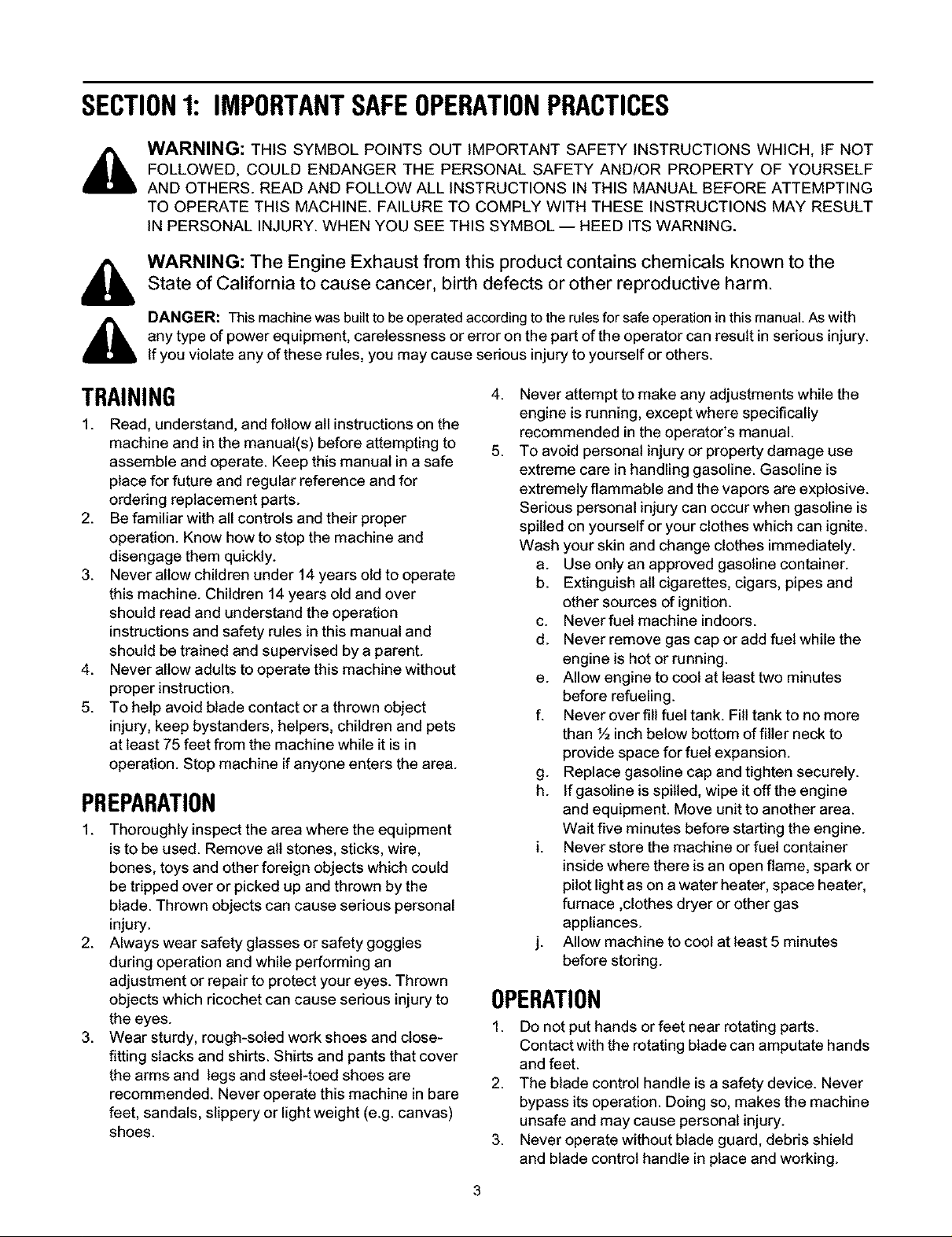
_lb WARNING:YOUR RESPONSIBILITY
Restrict the use of this power machine to persons who read, understand and follow the warnings
and instructions in this manual and on the machine.
Rotating cutting blade may throw objects
causing personal injury. Aiways wear eye
protection during operation. Keep area
clear of bystanders and do not operate
without guards in place. Read Operator's
Manuai before use.
Figure 1
4
Page 5
SECTION2: ASSEMBLINGYOUREDGER
IMPORTANT: This unit is shipped WITHOUT
GASOLINE or OIL. After setting up the unit, service
engine with gasoline and oil as instructed in the
separate engine manual packed with your unit.
NOTE: Reference to right or left hand side of the edger
is observed from the operating position.
Contentsof Carton
One Edger Assembly
One Plastic Bag Containing:
Edger Operator's Manual
Registration Card
Briggs & Stratton Operator!Owner Manual
One Clutch Rod (747-1164) with
One Ferrule (711-0392)
Two Flat Washers (736-0264) and
Two Hairpin Clips (714-0104) in place
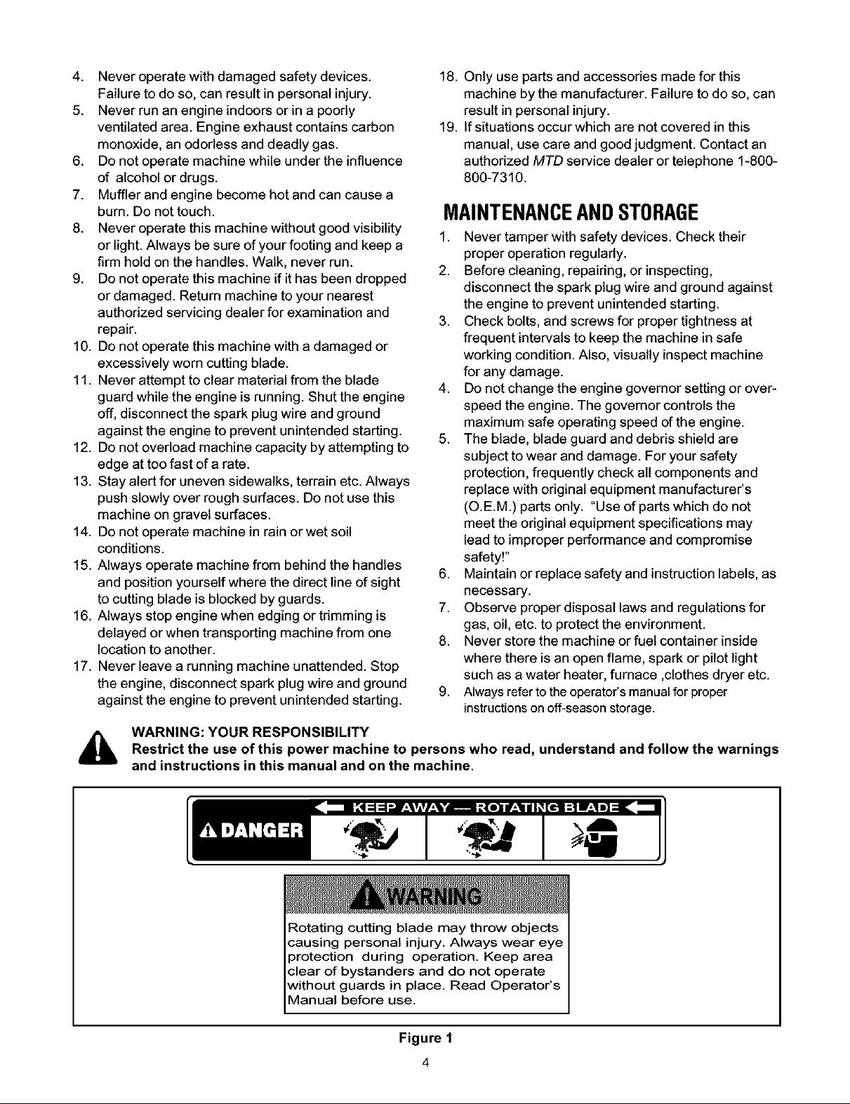
Groundingthe Engine'sSparkPlug
Disconnect the spark plug wire from the spark plug
and ground it on the top of the engine by placing its
rubber boot snugly over a bolt head. See Figure 2.
Rubber Boot
Spark Plug Wire
styles vary by model.
Upper Handle
Lower Handle
Figure 3
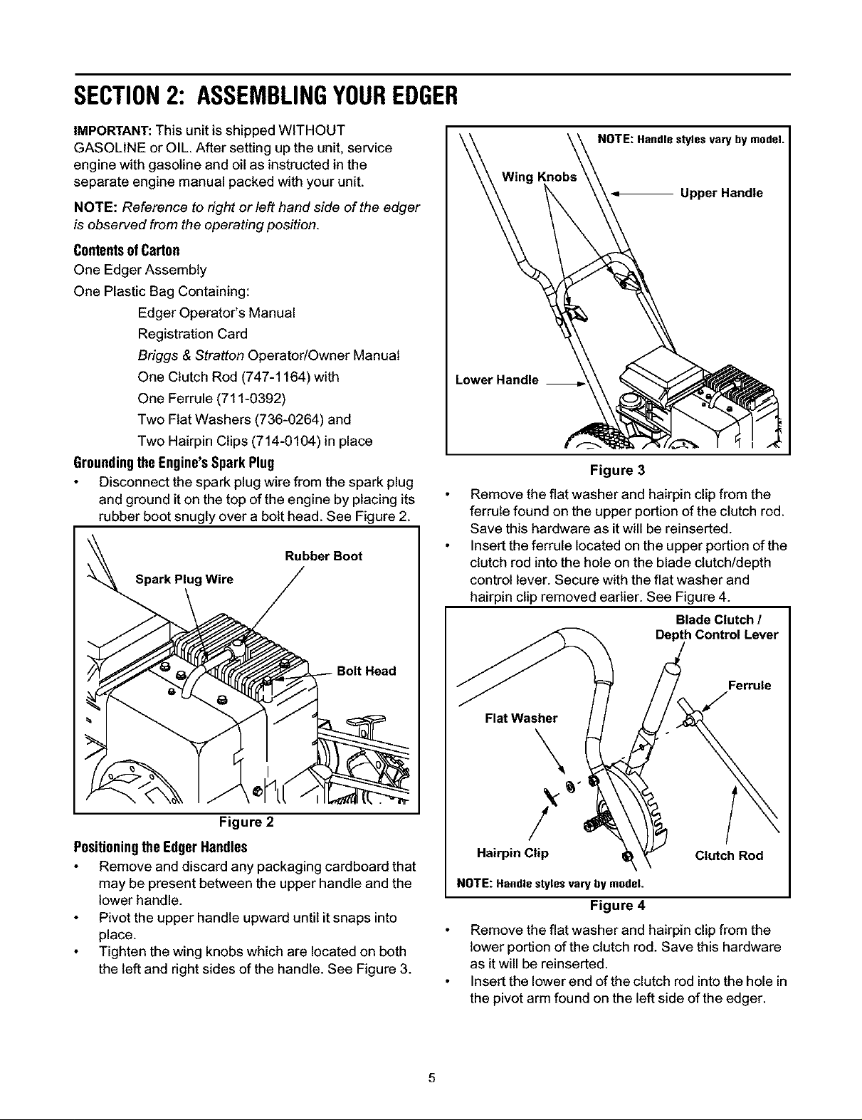
Remove the flat washer and hairpinclip from the
ferrule found on the upper portionof the clutch rod.
Save this hardware as itwill be reinserted.
Insert the ferrule located on the upper portion ofthe
clutchrod into the hole on the blade clutch/depth
controllever. Secure with the flat washer and
hairpin clip removed earlier. See Figure 4.
Blade Clutch t
Depth Control Lever
Bolt Head
Figure 2
Positioningthe EdgerHandles
Remove and discard any packaging cardboard that
may be present between the upper handle and the
lower handle.
Pivot the upper handle upward until it snaps into
place.
Tighten the wing knobs which are located on both
the left and right sides of the handle. See Figure 3.
Ferrule
Flat Washer
\
Hairpin Clip Clutch Rod
NOTE:Handlestyles vary by model.
Figure 4
Remove the flat washer and hairpin clip from the
lower portion of the clutch rod. Save this hardware
as it will be reinserted.
Insert the lower end of the clutch rod into the hole in
the pivot arm found on the left side of the edger.
Page 6

Securewiththeflatwasherandhairpinclip
removedearlier.SeeFigure5.
Hairpin Clip \\
\ \\ C,u,chRoO
_'_J _, Flat Washer_!
j Pivot Arm
Figure 5
IMPORTANT:Perform the clutchrod adjustment before
operating the edger.
ClutchRodAdjustment
Before operating the edger, check the adjustment of the
clutch rod as follows:
Disconnect the spark plug wire and ground it as
instructed earlier in this section. Refer to Figure 2.
With the blade clutch/depth control lever in the
disengaged position (the top notch in the depth
adjustment bracket), carefully pull the recoil starter
rope. The blade on the edger should not turn. If the
blade turns, remove the ferrule from the blade
clutch/depth control lever by first removing the
hairpin clip and flat washer.
Rotate the ferrule clockwise one or two turns on the
clutch rod, then re-insert the ferrule into the lever
and recheck the adjustment.
After adjusting, check to be certain the blade clutch/
depth control lever can be moved to the furthest
notch forward without bowing the clutch rod. If it
can't, recheck the adjustment.
IMPORTANT: Be certain that the clutch rod is secured at
both ends with a flat washer and hairpin clip before
operating the edger.
SECTION3: KNOWTHEEDGER
ThrottleControl
The throttle control lever is located on the engine. It can
be adjusted to regulate the engine speed only.
NOTE: Refer to the Briggs & Stratton Operator/Owner
Manual packed with your edger for a detailed
description of all engine-related controls and
components.
ChokeControl
The choke control lever is located on the engine. Itis
used to aid in starting a cold engine.
NOTE: Refer to the Briggs & Stratton Operator/Owner
Manual packed with your edger for a detailed
description of all engine-related controls and
components.
BladeClutch/ DepthControlLever
The blade clutch!depth control lever is located on the
right side of the upper handle. It is used to engage and
disengage the edger blade. Itis also used to control the
depth of the cut. The further forward the control lever is
moved, the deeper into the soil the edger blade will cut.
,_ WARNING: When operating the edger, stop
engine immediately and readjust the clutch
rod if the blade turns with the blade clutch/
depth control lever in the disengaged position.
Pull Rope/ RecoilStarter
The pull rope!recoil starter is used to start the engine.
NOTE: Refer to the Briggs & Stratton Operator/Owner
Manual packed with your edger for a detailed
description of all engine-related controls and
components.
BladeAngleAdjustmentLever
The blade angle adjustment lever is located on the
front, left portion of the edger, behind the edger blade. It
is used to vary the angle of the edger blade between
one of eight positions from trenching to trimming.
CurbHeightAdjustmentLever
The curb height adjustment lever is found on the rear,
right portion of the edger. It aids in stabilizing the edger
operating along a curb.
IMPORTANT: Become familiar with all the controls
before operating the edger.
Page 7

Throttle Control &
Choke Control
Curb Height
Adjustment Lever
Pull Rope / Recoil Starter
NOTE: Handle, wheel and blade styles vary by model. Yours may differ slightly.
Figure 6
SECTION4: OPERATINGTHEEDGER
Blade Clutch /
Depth Control Lever
Blade Angle
Adjustment Lever
The operation of any edger can result
in foreign objects being thrown into
the eyes, which can result in severe
eye damage. Always wear safety
glasses or eye shields. We
recommend wide vision safety mask
for over spectacles or standard
safety glasses
WARNING: Do not lower blade if blade is
over concrete, asphalt, rocks or the like. The
blade can strike the supporting surface,
resulting in personal injury or property
damage.
AddingGasolineAndOil
Service the engine with gasoline and oil as instructedin
the Briggs & Stratton Operator/Owner Manual packed
with your edger. Read instructions carefully.
WARNING: Never fill fuel tank indoors, with
engine running or until the engine has been
allowed to cool for at least two minutes after
running.
To start the edger's engine, proceed as follows:
Attach the spark plug wire to the spark plug. Make
certain the metal cap on the end of the spark plug
wire is fastened securely over the metal tip on the
spark plug.
Move the blade clutch/depth control lever back to
the disengaged position, and place it in the
adjacent (top) notch.
Move the choke control lever on the engine into the
CHOKE or START position.
Move the throttle control lever on the engine into
the FAST (Rabbit) position.
Grasp the starter handle and slowly pull the rope
outward until engine reaches the start of its
compression cycle (the rope will pull slightly harder
at this point).
After slowly allowing the rope to recoil, pull the rope
with a rapid, continuous, full arm stroke. Keep a firm
grip on starter handle throughout the entire stroke.
Allow the starter handle to slowly recoil into the
engine.
Slowly move the choke control lever on the engine
into the RUN position after the engine has started.
StartingTheEngine
NOTE: Refer to the Briggs & Stratton Operator/Owner
Manual packed with your edger for a detailed
description of aft engine-related controls and
components.
StoppingTheEngine
To stop the edger's engine, proceed as follows:
Move the blade clutch/depth control lever back to
the disengaged position, and place it in the
adjacent (top) notch.
Page 8

Movethethrottlecontrolleverontheengineinto
the STOP or OFF position.
IMPORTANT: Make certain that the engine's spark plug
wire is properly grounded as instructed in SECTION 2:
Assembling The Edger before storing the edger for its
next use. Refer to Figure 2.
Engagingthe EdgerBlade
WARNING: The blade clutch!depth control
lever is designed to minimize the risk of blade
contact injury. Do not under any
circumstances attempt to defeat the function
of the blade clutch!depth control, or use the
edger if the control is not adjusted properly.
WARNING: Keep hands and feet away from
edger blade whenever the engine is running,
whether blade is engaged or disengaged.
To disengage the blade, proceed as follows:
Move the blade clutch!depth control lever to the left
and place it in the top notch in the depth adjustment
bracket. See Figure 7.
Blade Clutch /
Depth Control Lever
Bracket
The blade clutch/depth control lever has two
main functions:
1. To engage and disengage the blade.
2. To control the depth of cut.
SECTION5: MAKINGADJUSTMENTS
FrontWheelAdjustment
WARNING: Always place the blade clutch/
depth control lever in the DISENGAGED
position and turn the edger's engine off before
performing any adjustments.
Before operating the edger with the blade inthe
trimming (horizontal) position, it is necessary to alter
the position of the front, left wheel.
When operating the edger with the curb wheel lowered
(on models so equipped), it is necessary to alter the
position of the front, right wheel. To do either, proceed
as follows:
To change position of the front, left wheel, remove
the hairpin clip on the left. To change position of the
front, right wheel, remove the hairpin clip on the
right. See Figure 8.
Reposition the wheel by sliding it down the front
axle toward the opposite wheel. See Figure 8.
Secure the wheel in its new location by inserting the
hairpin clip removed earlier in the hole found
immediately adjacent to it. See Figure 8.
NOTE:Handlestyles vary by model.
Figure 7
To engage the blade, proceed as follows:
Move the control lever to the left and place it into
any of the five lower notches. The further forward
the blade clutch/depth control lever is moved, the
deeper or lower the blade wilt cut into the ground.
Clips
NOTE: Wheel stylesvary bymodel.
Figure 8
Page 9

EdgerBladeAngleAdjustment
WARNING: Rotating cutting blade may throw
objects causing personal injury. Keep area
clear of bystanders and do not operate
without guards in place.
The cutting blade can be adjusted to eight positions. To
adjust the blade angle, proceed as follows:
Place the blade clutch!depth control lever in the
disengaged position (top notch).
Edging
Placing the blade angle adjustment lever in the second
notch from the right will put the spindle assembly at a
90° angle for vertical edging as illustrated in Figure 11.
,i_ WARNING: Always place the blade clutch/
Trenching
Placing the blade angle adjustment lever in the notch
furthest to the right will put the spindle assembly at a
proper angle for trenching with the edger as illustrated
in Figure 10.
depth control lever in the DISENGAGED
position before adjusting the blade angle.
Pull forward on the blade angle adjustment lever
before rotating the spindle assembly.
Release the blade angle adjustment lever into one
of the notches on the pivot bracket. See Figure 9.
Blade Angle
Adjustment Lever
Pivot Bracket
Spindle Assembly
Figure 9
NOTE: Wheel styles vary by model.
Figure 11
Beveling
Placing the blade angle adjustment lever in the third,
fourth, fifth, sixth or seventh notch (from the right) wilt
put the spindle assembly at various angles for beveling
with the edger as illustrated in Figure 12.
IMPORTANT:When the spindle assembly is rotated
counter-clockwise (putting the blade closer to a
horizontal position), it IS necessary to change the
position of the front, left wheel to prevent the edger
blade from striking the wheel. See FrontWheelAdjustment
earlier in this section.
NOTE: Wheelstylesvary by model.
Figure 10
NOTE: Wheel styles vary by model.
/
Figure 12
WARNING: Always place the blade clutch/
depth control lever in the DISENGAGED
position before adjusting the blade angle.
Page 10

Trimming
Placing the blade angle adjustment lever in the notch
furthest to the left will put the spindle assembly at a
proper angle for trimming with the edger as illustrated in
Figure 13.
IMPORTANT: When the spindle assembly is rotated
counter-clockwise (putting the blade closer to a
horizontal position), it IS necessary to change the
position of the front, left wheel to prevent the edger
blade from striking the wheel. See FrontWheelAdjustment
earlier in this section.
tit I
To adjust the height of the curb wheel, proceed as
follows:
Perform the FrontWheelAdjustmentfor curb wheel
operation as instructed earlier in this section.
Lower the right, rear wheel by moving the curb
height adjustment lever slightly to the left.
Place the right, rear wheel into an applicable
position in relation to the height of the curb to be
edged along.
Release the curb height adjustment lever to lock
the wheel in position. See Figure 14.
NOTE: Wheel styles vary by model.
Figure 13
CurbWheelAdjustment
NOTE: The curb wheel is NOT standard on all units.
On models so equipped, the right, rear wheel of the
edger can be lowered into one of five positions to ease
the task of edging along a curb.
NOTE: Wheel stylesvary by model.
Figure 14
SECTION6: MAINTAINING& SERVICINGTHEEDGER
PivotPoints
,_ WARNING: Disconnect the spark plug wire
and ground against the engine before
performing any adjustment, repairs or
maintenance. Refer to Figure 2.
Lubrication
Engine
Refer to the Briggs & Stratton Operator/Owner Manual
packed with your edger for a detailed description of all
engine-related service specifications.
Wheels& FrontAxle
Lubricate the wheels and front axle at least once a
season with a light oil. Also if the wheels are removed
for any reason, lubricate the surface of the axle bolt and
the inner surface of the wheel with light oil.
Lubricate the pivot points on the blade angle
adjustment lever, blade clutch/depth control lever and
curb height adjustment lever with light oil at least once a
season.
CuttingHeadBearings
The two ball bearings in the blade spindle housing are
lubricated and sealed at the factory and require no
lubrication.
SpindleShaft
Lubricate the two shoulder spacers and the entire area
surrounding the compression spring on the edger's
spindle shaft with light oil (NOT WD-40) frequently
during the season. Do NOT allow rust to form in this
area. See Figure 15.
10
Page 11

Figure 15
Remove the blade spindle belt guard by removing
the hex screws, two lock washers and two hex nuts
which secure it to the blade spindle plate. See
Figure 17.
Blade Spindle Plate
Shoulder Spacer
Compression Spring
(Lubricate welll)
Hex Screws
Blade Spindle
Belt Guard NOTE:Bladestylesvarybymodel.
ReplacingtheEdgerBlade
Use two wrenches (one wrench to prevent the hex
bolt head from spinning and the other to remove the
hex lock nut) to remove the edger blade. See
Figure 16.
Bell Washer
Hex Bolt Head
Hex Lock Nut
NOTE: Wheeland bladestylesvary by model.
Figure 16
Remove and discardthe edger blade but retain the
bell washer and hex lock nut.
Installthe replacement edger blade, the bell
washer (cupped side facing inward) and the hex
lock nutremoved earlier.
IMPORTANT: Use a torque wrench to tighten the hex
lock nut to between 37 foot-lbs, and 50 foot- Ibs.
Replacingthe DriveBelt
The edger drive belt is subject to wear and should be
replaced if any signs of cracking, shredding or rotting
are present. To replace the belt, proceed as follows:
Place the blade angle adjustment lever in the
edging position. Refer to Figure 11.
Figure 17
Remove the beltfrom around the blade spindle
pulley.
Place the blade clutch!depth control lever in the
lowest notch (all the way forward).
Remove the engine pulley belt guard by removing
the two hex screws and two lock washers which
secure it to the engine block. See Figure 18.
Hex
Figure 18
Remove the belt from around the engine pulley.
Install the replacement drive belt around both the
blade spindle pulley and the engine pulley.
Reattach the blade spindle belt guard to the blade
spindle plate with the hardware removed earlier.
Reattach the engine pulley belt guard to the engine
block with the hardware removed earlier.
,_ WARNING: Never operate the edger without
both the blade spindle belt guard and the
engine pulley belt guard in place.
11
Page 12

SECTION7: OFF-SEASONSTORAGE
Observe the following when preparing the edger for
long-term storage:
Clean and lubricate unit thoroughly as instructed on
page 10 of this manual.
Refer to the Briggs & Stratton Operator/Owner
Manual packed separately with the edger for
engine manufacturers's storage instructions.
Coat the edger blade with chassis grease to
prevent rusting and corrosion.
SECTION8: TROUBLESHOOTING
Trouble Possible Cause(s)
Engine fails to start Dirty air cleaner
Engine needs to be primed
Fuel tank empty
Stale fuel in gasoline tank
Throttle control lever not in
starting position
Spark plug wire disconnected.
Spark plug fouled
Engine flooded
Engine runs erratic
Engine overheats Engine oil level low
Excessive vibration Edger blade bent or damaged
Drive belt slips Belt wom or stretched
Spark plug wire loose
Stale fuel in gasoline tank
Vent in gas cap plugged
Water or dirt in fuel system
Dirty air cleaner
Carburetor out of adjustment
Air flow restricted
Dirty air filter
Carburetor not adjusted properly
Blade spindle bent or damaged
Store the edger in a dry, clean area. Do not store
next to any corrosive matedals, such as lawn
fertilizer.
Coat the edger, especially any springs and
bearings with a light oil or silicone spray.
IMPORTANT:When storing any type of power
equipment in an poorly ventilated or metal storage
shed, care should be taken to rustproof the equipment.
Corrective Action
Refer to the Briggs & Stratton Operator/Owner Manual
packed with your unit.
Push primer bulb two or three times.
Fill tank with clean, fresh gasoline.
Drain gasoline and refill tank with clean, fresh gasoline.
Move throttle lever to FAST position.
Connect the spark plug wire to the spark plug.
Clean, adjust gap or replace spark plug.
Refer to the Briggs & Stratton Operator/Owner Manual
packed with your unit.
Connect and tighten spark plug wire.
Drain gasoline and refill tank with clean, fresh gasoline.
Clear vent of any debds.
Drain fuel tank. Refill with fresh fuel.
Refer to the Briggs & Stratton Operator/Owner Manual
packed with your unit.
Refer to the Briggs & Stratton Operator/Owner Manual
packed with your unit.
Fill crankcase with proper oil.
Clean the area around the engine's cooling fins.
Replace the engine's air filter
Refer to the Briggs & Stratton Operator/Owner Manual
packed with your unit.
Replace edger blade.
Contact an authodzed MTD service dealer.
Replace drive belt.
12
Page 13

SECTION9: MODELSERIES580 PARTSLIST
17
12
20
23
24
V-BELTS are specially designed to engage and
disengage safely. A substitute (non-OEM) V-Belt
can be dangerous by not disengaging completely.
Ref.
No.
1.
2.
3.
4.
5.
6.
7.
8.
9.
10.
11.
12.
13.
14.
15.
Part Number Description Description
712-0413
736-0317
781-0076
750-0118
712-0287
736-0329
05034A
741-0155
715-0121
781-0093
781-0078
710-0751
750-0229
756-0449
710-0929
Hex Jam Nut, 5/8-18
Bell Washer, .64 x 1.25 x .18
Blade Guard
Sleeve, .632 x .875 x .90
Hex Nut, 1/4-20
Lock Washer, 1/4
Bearing Housing
Ball Bearing, .62 x 1.38 x .44
Spirol Pin, 1/4 x2.0
Adjustment Lever Assembly
Spindle Plate/Shaft Assembly
Hex Cap Screw, 1/4-20 x .62
Spacer, .635 x .88 x 1.03
Sheave, .6255 x .6295
Hex Cap Screw, 5/8-18 x 4.5
Ref.
No.
Part Number
16. 781-0086
17. 714-0122
18. 754-0142
19. 756-0327B
20. 687-0100
21. 712-0267
22. 736-0242
23. 736-0119
24. 710-0237
25. 710-0152
26. 736-0258
27. 748-0160
28. 781-0748
781-0080
29. 732-0188A
2
28
Spindle Pulley Belt Guard
Square Key, 3/16 x.75
V-belt, 3/8
Engine Pulley, 3/8 x .75 x 2.38
Engine Pulley Belt Guard
Hex Nut, 5/16-18
Befleville Washer, .340 x .872
Lock Washer, 5/16
Hex Cap Screw, 5/16-24 x .625
Hex Cap Screw, 3/8-24 x 1.0
Flat Washer, .385 x 1.0 x. 135
Spacer, .753 x 1.25 x .175
Triplex Edger Blade, 9"
Standard Edger Blade, 9"
Double-torsion Spring
13
Page 14

ModelSeries580 61
54
22
23
j45
24
24
25
>
Spindle assembly shown forreference only.
See page 13 for parts breakdown)
14
Page 15

ModelSeries580
Ref.
No.
1.
2.
3.
4.
5.
6.
7.
8.
9.
10.
11.
12.
13.
14.
15.
16.
17.
18.
19.
20.
21.
22.
23.
24.
25.
26.
27.
28.
29.
30.
31.
Part Number Description Part Number Description
712-0267
736-0119
712-0287
736-0329
781-0095
731-0725
781-0087
736-0342
710-0252
710-0751
710-0402
714-0115
712-0114
736-0112
711-0386
781-0090
715-0143
732-0187
711-0379
710-0607
736-0504
738-0108
734-1268
734-1781
736-0105
712-0241
736-0452
710-0793
781-0580
726-0221
734-1264
734-1797
714-0101
Hex Nut, 5/16-18
Lock Washer, 5/16
Hex Nut, 1/4-20
Lock Washer, 1/4
Debris Deflector
Debris Guard
Flap Bracket, 1.12 x 5.5
Flat Washer, .283 x .75 x .030
Hex Screw w/Nose, 1/4-20 x .85
Hex Screw, 1/4-20 x .62
Hex Screw, 5/16-18 x 4.5
Cotter Pin, 1/8 x 1.0
Slotted Hex Nut, 1/2-20
Sphere Washer, .531 x 1.6 x .045
Spacer, .38 x .50 x 3.75
Spindle Pivot Bracket Assembly
Spirol Pin, 1/4x 1.25
Compression Spring
Shoulder Spacer, .635 x .620
Self-tapping Screw, 5/16-18 x .50
Wave Washer, .510 x .75 x .017
Shoulder Screw, .498 x 1.45
T-tread Wheel (shown)
w/Ball Bearing, 8 x 1.75
Slot Tread Wheel
w/Plastic Bearing, 8 x 1.75
Spring Washer, .401 x .871 x .063
Hex Nut, 3/8-24
Bell Washer, .396 x 1.14 x .095
Round Head Ribbed-neck Bolt,
3/8-24 x .89
Front Axle Arm
Cap Speed Nut, 1/2
T-tread Wheel (shown)
w/Ball Bearing, 7 x 1.75
Slot Tread Wheel
w/Plastic Bearing, 7 x 1.75
Internal Cotter Pin, .08 x 1.42
No.
32.
33.
34.
35.
36.
37.
38.
39.
40.
41.
42.
43.
44.
45.
46.
47.
48.
49.
50.
51.
52.
53.
54.
55.
56.
57.
58.
59.
60.
61.
62.
63.
64.
65.
66.
738-0898
710-0654A
714-0104
736-0264
736-3050
711-0392
712-0266
732-0552
749-0941
781-0075
738-0258
736-0255
736-0272
750-0535
736-0169
712-0798
781-0100
720-0241
736-0451
710-1174
749-0666
736-0271
710-3103
749-0937
749-0936A
781-0081
732-0369
736-0204
712-0158
720-0283
747-1164
681-0044
720-0297
781-0091A
749-0938
Front Axle, .50 x 7.98
Self-tapping Screw, 3/8-16 x 1.0
Internal Cotter Pin, .072 x 1.0
Flat Washer, .330 x .630 x .0635
Flat Washer, .406 x .810 x .051
Adjustment Ferrule
Center Lock Nut, 3/8-24
Curb Adjustment Lever Assembly
Support Strut, 15.91
Spindle Extension Arm
Shoulder Screw, .498 x .250
Bell Washer, .51 x 1.14 x .040
Flat Washer, .51 x 1.0 x .060
Spacer, .376 x .625 x .22
Lock Washer, 3/8
Hex Nut, 3/8-16
Curb Height Adjustment Plate
Wing Knob Assembly
Saddle Washer, .320 x .93
Curved Head Carriage Bolt,
5/16-18 x .75
Blade Clutch/Depth Control Lever
Spring Washer, .317 x .625 x .099
Hex Cap Screw, 5/16-18 x 2.0
Lower Handle
Upper Handle (Loop Style)
Depth Adjustment Bracket
Compression Spring, .55 x 1.37
Flat Washer, .344 x .62 x .030
Hex Lock Nut, 5/16-18
Foam Grip
Clutch Rod, 3/8 x 33.5
Edger Base
Foam Grip (Loop Handle), 20
Upper Handle Support Plate
Upper Handle (T-Style)
Ref.
15
Page 16

MANUFACTURER'S LIMITED WARRANTY FOR:
YARD
The limited warranty set forth below is given by MTD
PRODUCTS INC ("MTD") with respect to new merchandise
purchased and used in the United States, its possessions
and territories.
MTD warrants this product against defects in material and
workmanship for a period of two (2) years commencing on
the date of original purchase and will, at its option, repair or
replace, free of charge, any part found to be defective in
material or workmanship. This limited warranty shall only
apply if this product has been operated and maintained in
accordance with the Operator's Manual furnished with the
product, and has not been subject to misuse, abuse, com-
mercial use, neglect, accident, improper maintenance,
alteration, vandalism, theft, fire, water or damage because
of other peril or natural disaster. Damage resulting from the
installation or use of any accessory or attachment not
approved by MTD Products Inc. for use with the product(s)
covered by this manual will void your warranty as to any
resulting damages.
Normal wear parts or components thereof are subject to
separate terms as follows: All normal wear part or compo-
nent failures will be covered on the product for a period of
90 days regardless of cause. After 90 days, but within the
two year period, normal wear part failures will be covered
ONLY IF caused by defects in material or workmanship of
OTHER component parts. Normal wear parts and compo-
nents include, but are not limited to. belts, blades, blade
adapters, grass bags, rider deck wheels, seats, snow
thrower skid shoes, shave plates and tires. Batteries are
covered by a 90-day limited replacement warranty.
HOW TO OBTAIN SERVICE: Warranty service is available,
WITH PROOF OF PURCHASE THROUGH YOUR LOCAL
AUTHORIZED SERVICE DEALER. To locate the dealer in
your area, please check for a listing in the Yellow Pages or
contact the Customer Service Department of MTD PROD-
UCTS INC by calling 1-800-800-7310 or writing to RO. Box
368022, Cleveland. Ohio 44136-9722.
This limited warranty does not provide coverage in the
following cases:
a, The engine or component parts thereof, These items
carry a separate manufacturer's warranty. Please refer
to the applicable manufacturer's warranty on these
items.
b. Log splitter pumps, valves and cylinders have a sepa-
rate one year warranty.
c. Routine maintenance items such as lubricants, filters,
blade sharpening and tune-ups, or adjustments such
as brake adjustments, clutch adjustments or deck
adjustments; and normal deterioration of the exterior
finish due to use or exposure.
d. MTD does not extend any warranty for products sold
or exported outside of the United States of America.
its possessions and territories, except those sold
through MTD's authorized channels of export distribu-
tion.
No implied warranty, including any implied warranty of
merchantability or fitness for a particular purpose,
applies after the applicable period of express written
warranty above as to the parts as identified. No other
express warranty or guaranty, whether written or oral,
except as mentioned above, given by any person or
entity, including a dealer or retailer, with respect to any
product shall bind MTD. During the period of the War-
ranty, the exclusive remedy is repair or replacement of
the product as set forth above. (Some states do not
allow limitations on how long an implied warranty lasts, so
the above limitation may not apply to you.)
The provisions as set forth in this Warranty provide the
sole and exclusive remedy arising from the sales. MTD
shall not be liable for incidental or consequential loss
or damages including, without limitation, expenses
incurred for substitute or replacement lawn care ser-
vices, for transportation or for related expenses, or for
rental expenses to temporarily replace a warranted
product. (Some states do not allow the exclusion or limita-
tion of incidental or consequential damages, so the above
exclusion or limitation may not apply to you.)
In no event shall recovery of any kind be greater than the
amount of the purchase price of the product sold. Alteration
of the safety features of the product shall void this War-
rarity. You assume the risk and liability for loss, damage, or
injury to you and your property and/or to others and their
property arising out of the use or misuse or inability to use
the product.
This limited warranty shall not extend to anyone other than
the original purchaser, original lessee or the person for
whom it was purchased as a gift.
How State Law Relates to this Warranty: This limited
warranty gives you specific legal rights, and you may also
have other rights which vary from state to state.
 Loading...