

Page 1
Service Manual
2005 - 250 Series - World Tiller
NOTE: These materials are for use by trained technicians who are experienced in the service and repair of outdoor power
equipment of the kind described in this publication, and are not intended for use by untrained or inexperienced individuals.
These materials are intended to provide supplemental information to assist the trained technician. Untrained or inexperienced individuals should seek the assistance of an experienced and trained professional. Read, understand, and follow all
instructions and use common sense when working on power equipment. This includes the contents of the product’s Operators Manual, supplied with the equipment. No liability can be accepted for any inaccuracies or omission in this publication,
although care has been taken to make it as complete and accurate as possible at the time of publication. However, due to
the variety of outdoor power equipment and continuing product changes that occur over time, updates will be made to these
instructions from time to time. Therefore, it may be necessary to obtain the latest materials before servicing or repairing a
product. The company reserves the right to make changes at any time to this publication without prior notice and without
incurring an obligation to make such changes to previously published versions. Instructions, photographs and illustrations
used in this publication are for reference use only and may not depict actual model and component parts.
© Copyright 2005 MTD Products Inc. All Rights Reserved
MTD Products Inc - Product Training and Education Department
FORM NUMBER - 769-02094
10/2005
Page 2

Page 3

TABLE OF CONTENTS
Introduction ............................................................................................................................1
Tines ......................................................................................................................................3
Clutching Mechanism ............................................................................................................4
Gearbox Removal and Replacement. ...................................................................................7
Gearbox Maintenance and Repair. .......................................................................................9
Seal Replacement ...............................................................................................................15
Page 4

Page 5
Vertical Crankshaft Front Tine Tiller
Vertical Crankshaft Front Tine Tiller
1. INTRODUCTION
1.1. Disclaimer: This service manual was intended
for use by trained technicians. The information
contained in this manual is current and accurate
at the time of writing, but is subject to change
without notice.
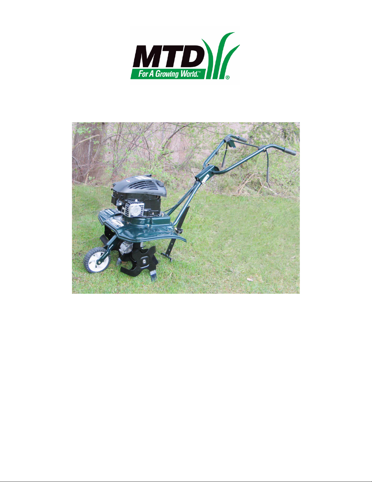
1.2. Purpose: The vertical crankshaft front tine tiller
was designed to provide a high value tool for
homeowners and gardeners who do not need a
large rear-tine tiller but require something larger
than a cultivator. This product is small enough to
be handy yet large enough to get the job done.
Standard rotating tine tillers excel at turning soil
that has previously been broken. This means
turning-over and introducing compost into existing flower beds and gardens. While it is capable
of breaking untilled soil, a counter-rotating tine
tiller is better suited to that task. The vertical
crankshaft design yields savings in engine cost.
See Figure 1.2.
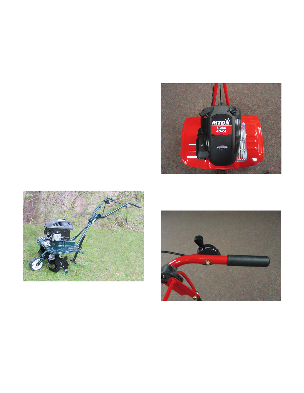
1.4. Other Versions: The tiller depicted here is just
one of a variety of vertical crankshaft front-tine
tillers currently in production. See Figure 1.4.
Figure 1.4
1.5. Versions of this tiller are distributed in Europe.
Features on export tillers vary slightly from
domestic tillers. See Figure 1.5.
Figure 1.2
1.3. Description: The standard (forward) rotating
tines are driven by a set of worm gears within
the transmission. The tines can be adjusted to till
a swath that varies from 13” (33cm) to 24”
(61cm). The clutching media is a belt that is tensioned between two halves of a split sheave.
One half is attached to the engine, and the other
half is attached to the worm shaft. The friction of
the belt between the two sheave halves transfers power from the engine to the worm shaft at
a 1:1 ratio.
Figure 1.5
1
Page 6
Vertical Crankshaft Front Tine Tiller
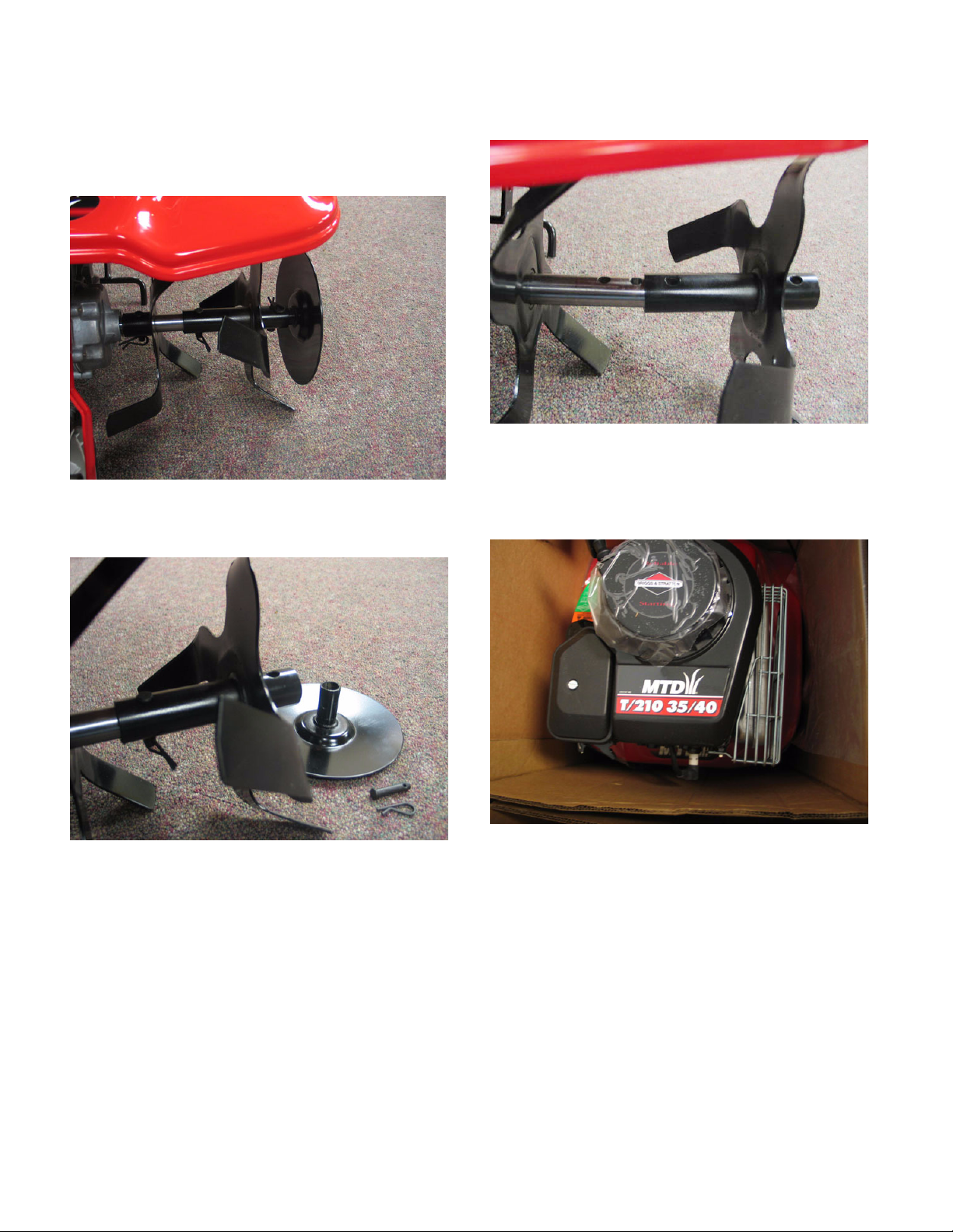
1.6. Different widths and tine configurations are in
production. The T-250 44cm/61cm version has a
disc on the end of the tine shaft to confine trailings. See Figure 1.6.
Figure 1.6
1.7. The disc can be removed. See Figure 1.7.
1.8. The tines can be reconfigured. See Figure 1.8.
Figure 1.8
1.9. There is also a T-210 35cm/40cm version,
roughly 50% larger than a mini cultivator.
See Figure 1.9.
Figure 1.7
Figure 1.9
2
Page 7

Vertical Crankshaft Front Tine Tiller
2. TINES
2.1. Disconnect and ground the spark plug wire
before servicing or adjusting the tines.
2.2. The tines are easily removed or adjusted using
the hairpin clips and clevis pins that fasten them
to the tine shaft. See Figure 2.2.
Long hub
Hairpin
Short hub
Figure 2.2
clips
2.4. There are left and right side tines, each has a
different angle of attack. The tines must sweep
away from the dirt as they enter it. If the tines are
reversed left/right, they will hook into the dirt too
aggressively. See Figure 2.4.
Right hand tine
Rotation Rotation
Figure 2.4
Left hand tine
2.3. The tines have two types of hub tube: long, and
short.
2.5. Keep the tine shaft clear of wire fencing, monofilament, clothesline and other material that may
wrap around the shaft.
2.6. Penetrating oil may be used to loosen tines that
are corroded to the tine shaft.
• Lubricating the tine shaft before storage will help
prevent this condition.
• A small amount of anti-seize between the tine
hub tubes and the tine shaft will help prevent this
condition.
2.7. Replace the tines and the hardware that secures
them to the tine shaft when they become visibly
worn.
3
Page 8

Vertical Crankshaft Front Tine Tiller
3. CLUTCHING MECHANISM
3.1. Disconnect and ground the spark plug wire
before performing a service or adjustments to
the clutching mechanism. If the engine has been
recently been run allow it to cool before service
is performed.
3.2. The clutching mechanism consists of the clutch
control lever, clutch cable, belt, upper and lower
sheaves, and belt tensioner.
3.3. Service to most of these components require the
removal of the engine.
3.4. Removal of engine and clutch housing.
See Figure 3.4.
3.5. To remove the cable, detach the cable from the
handlebars by pushing the barbed bracket out of
the hole. See Figure 3.5.
Clutch control
lever
Figure 3.5
3.6. Disconnect the Z-fitting from the lever.
3.7. Turn the engine upside-down to gain access to
the cable connection inside the clutch housing.
See Figure 3.7.
Z-fitting
Figure 3.4
NOTE: Removal steps
• Remove the 6 bolts and locking nuts that hold
the clutch housing to the rest of the tiller, using a
pair of 9/16” wrenches.
• Lift the engine and clutch housing from the tiller
and place them on a flat level surface without
constraining the cable.
• If the engine is to be inverted, drain the gasoline
from the fuel tank.
Idler
bracket
Figure 3.7
NOTE: The orientation of spring is hooking from
the bottom.
4
Page 9

Vertical Crankshaft Front Tine Tiller
3.8. Remove snap ring that attaches the cable to the
clutch housing.
3.9. Disconnect the cable from the idler bracket.
See Figure 3.9.
Snap ring
Figure 3.9
3.10. Install the cable by reversing the order of
removal.
3.11. To remove the belt, it will be necessary to
remove the idler bracket
3.14. Lift the idler bracket and belt out of housing.
See Figure 3.14.
Figure 3.14
3.15. Remove the lock nut from the stud by using a
9/16” wrench. See Figure 3.15.
Belt keeper
tabs
3.12. Disconnect the return spring from the idler
bracket.
3.13. Remove the 3/4 “ hex shoulder bolt and 9/16
lock nut on top side of clutch housing.
See Figure 3.13.
Idler
return
spring
Shoulder bolt
Figure 3.13
Figure 3.15
NOTE: Belt keeper tabs perform a braking func-
tion when the belt is released.
NOTE: Belt pt# 754-04061 Use of a non-standard belt may result in poor performance or loss
of braking feature creating a unsafe condition.
5
Page 10

Vertical Crankshaft Front Tine Tiller
3.16. If it is necessary to remove the top half of the
sheave from the engine crankshaft, apply heat to
the socket head cap screw to release the thread
locking compound. See Figure 3.16.
Figure 3.16
3.17. Remove the socket head cap screw with a 3/16”
allen wrench. See Figure 3.17.
3.20. With the engine and clutch housing removed,
the tine shield can be lifted off of the tiller.
See Figure 3.20.
Figure 3.20
NOTE: There are two dowels that locate the tine
shield to the tiller transmission.
3.21. If it is necessary to remove the lower half of the
sheave from the transmission worm shaft, apply
heat to release the thread locking compound.
See Figure 3.21.
Figure 3.17
NOTE: It may be necessary to stop the engine
from turning with either a piston stop or a flywheel holder.
NOTE: The sheave half that is attached to the
crank shaft provides fly weight for the engine.
3.18. At this point the clutch housing can be removed
from the engine using a 9/16” wrench.
3.19. On installation, apply thread locking compound
such as Loctite 242 (blue) the threads and
tighten to torque of 250-270 in-lbs (28-30 n-m)
RTV
sealant
Dowels
Figure 3.21
NOTE: There is a thin bead of RTV sealant
beneath the tine shield to help exclude dust from
the clutch housing. It does not necessarily seal
to the tine shield.
6
Page 11

Vertical Crankshaft Front Tine Tiller
3.22. Remove the socket head cap screw and heavy
washer that secure the lower half of the sheave
to the transmission worm shaft using a 3/16”
allen wrench. See Figure 3.22.
Lower
Pulley
Double-D
Shaft
Figure 3.22
3.23. The pulley adapter will slip off of the transmission worm shaft. It drives the shaft through a
double-D profile.
Pulley adaptor
4. GEARBOX REMOVAL AND REPLACEMENT.
NOTE: The tiller gear box is subject to the like
kind exchange program, providing that the failure is warrantable.
NOTE: Outside of warranty.the repair vs.
replacement will be at the discretion of the enduser and the repair shop.
4.1. Begin the transmission removal process by
Removing the engine and clutch housing. See
Figure 4.1.
NOTE: Some 2005 and later tillers may have a
low profile hex-head cap screw in place of the
socket head cap screw. It may be removed using
a 9/16” wrench.
3.24. On installation, apply thread locking compound
such as Loctite 242 (blue) to the threads and
tighten to a torque of 250-270 in-lbs (28-30 n-m).
Figure 4.1
• Remove the 6 bolts and locking nuts that hold
the clutch housing to the rest of the tiller, using a
pair of 9/16” wrenches.
• Lift the engine and clutch housing from the tiller
and place them on a flat level surface without
straining the cable.
• If the engine is to be inverted, drain the gasoline
from the fuel tank.
4.2. Lift the tine shield off transmission.
7
Page 12

Vertical Crankshaft Front Tine Tiller
4.3. Take note of the tine orientation, then remove
the tines. See Figure 4.3.
Figure 4.3
4.4. Remove the nut and bolt that hold the front
wheel bracket and tension spring to the transmission using a pair of 7/16” wrenches. See Figure 4.4.
4.7. To install the replacement gearbox simply
reverse the removal process.
See Figure 4.7.
NOTE: When Making service-or-replace decision about the gearbox, carefully evaluate the
value of the tiller.
Figure 4.7
Wheel bracket
bolt
Figure 4.4
NOTE: Tighten the wheel bracket bolt to a
torque of 90-120 in/lbs (10-13 n-m) on installation.
4.5. Remove 2 through-bolts that secure the handle
bars to the gearbox, using a pair of 1/2”
wrenches.
• If any major damage is discovered to the case,
the bronze gear, or the worm shaft, repair costs
will likely exceed the value of the transmission.
• Beyond warranty, confirm the amount that the
customer is willing to spend before commencing
any internal transmission repairs.
4.6. Remove 2 bolts that hold the depth bar bracket
on the gearbox, using a pair of 9/16” wrenches.
8
Page 13

Vertical Crankshaft Front Tine Tiller
5. GEARBOX MAINTENANCE AND REPAIR.
5.1. Gearbox contains 12 fl/oz. of 85w-140 gear lube.
NOTE: In normal service it should not be neces-
sary to change the gear lube on a regular basis.
The gear lube can be drained and replaced if the
transmission is to be opened for repair, or if the
fluid becomes contaminated, for example by
pressure washing.
NOTE: Damage caused by water in the transmission is NOT warrantable.
5.2. To check the fluid level clean the surface surrounding the fill plug. See Figure 5.2.
Gear lube
fill plug
5.4. When filling the gear box with the gear lube be
sure that the gear box is upright position, the oil
level will come up halfway on the tine shaft.
5.5. Drain and properly dispose of the gear lube if the
transmission is to be serviced. Refill it to the
proper level upon completion.
5.6. Before attempting to split the housing, clean the
tine shaft. Remove all dirt, rust, and scale using
emery cloth or a wire wheel.
NOTE: Wear eye protection.
5.7. Remove the 12 perimeter bolts that hold the two
case halves together using a 3/8” wrench, and
separate the housing.
See Figure 5.7.
Figure 5.2
5.3. Remove the fill plug with a 7/16” open end
wrench. See Figure 5.3.
Figure 5.3
NOTE: A bent piece of wire can be used as an
improvised dipstick.
Figure 5.7
NOTE: When assembling the gear box:
• Clean all components.
• Apply gear lube to the surfaces that rotate
against a seal.
• Protects seal lips on installation.
• Apply RTV sealant such as Permatex Ultra Grey
599BR to the mating surfaces of the case
halves.
• Tighten screws to a torque of 90-120 in/lbs (1013 n-m).
9
Page 14

Vertical Crankshaft Front Tine Tiller
5.8. Remove the shim from tine shaft inspect for any
wear to the shaft or gears. See Figure 5.8.
Shim
. 060
Figure 5.8
5.9. Pull Tine shaft through the gear.
See Figure 5.9.
5.10. Lift the bronze gear out of the housing after the
tine shaft has been removed.
See Figure 5.10.
NOTE: Gear tooth profile is concave to mate
with worm gear.
5.11. Inspect the bronze gear, bronze tine shaft bearings, tine shaft, and housings for significant wear
or damage.
Figure 5.10
Hi-Pro
key
Figure 5.9
NOTE: Hi-Pro key between the tine shaft and
the bronze gear.
5.12. Remove and inspect worm input shaft for wear
or damage to bearings.
See Figure 5.12.
Figure 5.12
10
Page 15

Vertical Crankshaft Front Tine Tiller
5.13. To remove the seals, simply pry them up with a
heavy screw driver.
See Figure 5.13.
Figure 5.13
NOTE: Care must be given not to score the
inside of the gear box casting.
5.14. If it is necessary to remove the bushings from
the housing that may be driven-out from the
inside. See Figure 5.14.
5.15. When installing new bushings, press them in so
that the end of the bushing is even with the
inside boss of the housing. See Figure 5.15.
Figure 5.15
NOTE: Bushing part number 741-04139
NOTE: If the tiller is need of tine shaft bearings
and the correct bearing (p/n 741-04139) is not
available, Troy-Bilt p/n GW-1086 may be modified by cutting off 3/8” for a suitable replacement.
Figure 5.14
NOTE: The bushing removal tool from the Troy-
Bilt tiller tine shaft tool kit TWX-4006 is the correct size.
NOTE: If you see that the bushings are in need
of replacement prior to taking out seals you can
press the seals out at the same time your removing the bushing
5.16. Scribe the GW-1086 bearing against the drivenout 741-04139 bearing to mark the length. See
Figure 5.16.
3/8”
Figure 5.16
11
Page 16

Vertical Crankshaft Front Tine Tiller
5.17. The GW-1086 bearing may be cut using a tubing
cutter, and dressed to clean any flash or burrs.
See Figure 5.17.
Figure 5.17
NOTE: When cutting down the bearing, do not
apply enough pressure to distort the bearing. Be
gentle.
5.20. With the screw and heavy washer removed, the
sheave-half can be lifted away, along with the
adapter. See Figure 5.20.
Pulley
Sheave
Adaptor
Figure 5.20
5.21. With the adaptor removed, the shim washers,
seal, and sealed ball bearing will slip off of the
s ha ft . Se e F i gu r e 5 .2 1.
5.18. The sheave half is most easily removed from the
worm shaft after the shaft has been removed
from the housing.
5.19. Fixture the shaft in a bench vise, and apply heat
to the socket head cap screw to release the
t h r e a d l o c k i n g c o m p o u n d . S e e F i g u r e 5 . 1 9 .
Hex head cap
screw
Figure 5.19
Figure 5.21
NOTE: Some tillers may have a hex head cap
screw at this location.
12
Page 17

Vertical Crankshaft Front Tine Tiller
5.22. The tapered roller bearing can be pressed off of
the bottom of the worm shaft. See Figure 5.22.
Figure 5.22
5.23. Inspect the bearings for roughness or obvious
damage. Replace them if necessary.
5.24. Replace the shim washers above the sealed
bearing, followed by a new seal.
See Figure 5.24.
5.26. Test fit the worm shaft assembly in the housing.
Check end-play. End play should be 0. 0-.014”
(.36 mm). See Figure 5.26.
Figure 5.26
NOTE: The closer to zero end play, the better.
5.27. Add or remove shims (p/n 736-0266 and 736-
04186) to achieve correct end-play. Generally,
this will not require adjustment.
Bearing
Shim washers Oil seal
Figure 5.24
NOTE:
Protect the lip of the new seal on installation.
5.25. Secure the pulley adapter and sheave half to the
worm shaft using the heavy washer and cap
screw. Do not torque the screw or apply thread
locking compound.
5.28. Remove the worm shaft from the housing, fixture
it in a bench vise, apply thread-locking compound such as Loctite 242 (blue) to the threads
of the cap screw securing the sheave, and
tighten it to a torque of 250-270 in-lb. (28-30 nm). See Figure 5.28.
Figure 5.28
5.29. Reposition the worm shaft assembly in the housing.
5.30. Position the first tine shaft thrust washer in the
housing.
13
Page 18

Vertical Crankshaft Front Tine Tiller
5.31. Place the bronze gear on top of the thrust
washer, confirming that the holes in the gear, the
thrust washer, and the tine shaft bearing are
aligned. See Figure 5.31.
Figure 5.31
5.32. Install the tine shaft, hi-pro key, and second
thrust washer.
5.34. Position the second half of the housing, and
secure it using the 12 screws previously
removed. Tighten the screws to a torque of 90120 in-lb. (10-13 n-m). See Figure 5.34.
Figure 5.34
5.35. Install the tine shaft seals. See Figure 5.35.
5.33. Apply a thin bead of RTV sealant such as Permatex Ultra Grey 599BR to the mating surfaces
of the case halves. See Figure 5.33.
Figure 5.33
Figure 5.35
5.36. Drive the seals all the way in, so that they seat
against the shoulder in the bore.
5.37. Re-fill the case with 12 fl/oz. of 80w140 gear lube
before operation.
5.38. Install the gearbox in the tiller by reversing the
removal process.
14
Page 19

Vertical Crankshaft Front Tine Tiller
6. SEAL REPLACEMENT
NOTE: Replacement of the seals can be done
without removing or disassembling the transmission.
NOTE: Drain fuel from the fuel tank.
NOTE: If the seal on the left side needs replace-
ment, drain the engine oil as well.
6.1. Position the tiller on its side, with the seal to be
replaced facing up. Remove tines from tine
shaft. See Figure 6.1.
6.3. After the seal is free from the transmission
housing it is possible to slide the seal off by
hand.
See Figure 6.3.
Figure 6.3
6.4. When the old seal has been removed examine
the tine shaft to for damage to the sealing surface. If the shaft is damaged there are two
options:
Figure 6.1
NOTE: It may be necessary to clean the tine
shaft with emery cloth prior to removing the seal.
6.2. Use seal puller tool or heavy screw driver to get
a hold on the old seal.
See Figure 6.2.
Figure 6.2
• Replace the shaft.
• Repair the shaft with a locally purchased “Reddisleeve” or similar product.
6.5. Use old micro fiche or similar material to protect
the seal a s i t slips over t h e tine shaft.
See Figure 6.5.
Figure 6.5
NOTE: Use caution not to score the shaft.
15
Page 20

Vertical Crankshaft Front Tine Tiller
6.6. Slide the seal along with the protective film or
sleeve into the tine shaft bore in the transmission housing.
See Figure 6.6.
NOTE: A light coating of oil on the shaft will aid
the film and seal down to the transmission.
Figure 6.6
6.7. Slide the film out of the seal.
See Figure 6.7.
6.8. Drive the seal home against the with Seal
installer tool from the Troy-Bilt tiller tine shaft tool
kit TWX-4006.
See Figure 6.8.
Figure 6.8
6.9. Install the tines.
6.10. Confirm correct gear lube and engine oil levels.
6.11. Run and test the tiller before delivery to the customer.
Figure 6.7
NOTE: Start the seal in the bore with gentle
thumb pressure.
16
 Loading...