

Page 1
Safety • Assembly • Operation • Tips & Techniques • Maintenance • Troubleshooting • Parts Lists • Warranty
OF A O AL
/
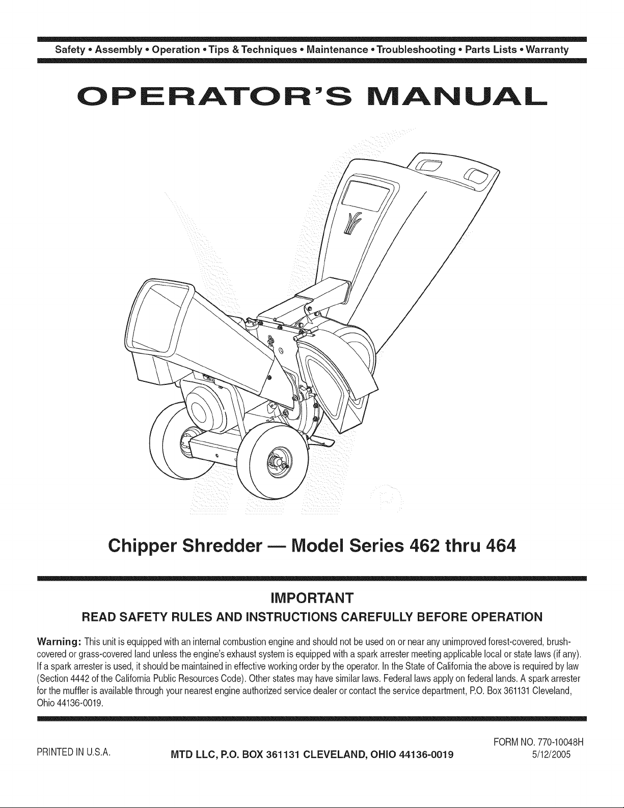
Chipper Shredder- Model Series 462 thru 464
iMPORTANT
READ SAFETY RULES AND iNSTRUCTiONS CAREFULLY BEFORE OPERATION
Warning: Thisunitisequippedwithaninternalcombustionengineandshouldnotbeusedon or nearanyunimprovedforest-covered,brush-
coveredor grass-coveredlandunlesstheengine'sexhaustsystemisequippedwitha sparkarrestermeetingapplicablelocalor statelaws(if any).
If a sparkarresterisused,it shouldbemaintainedineffectiveworkingorderby theoperator.IntheStateofCaliforniatheaboveisrequiredbylaw
(Section4442oftheCaliforniaPublicResourcesCode).Otherstatesmayhavesimilarlaws.Federallawsapplyonfederallands.A sparkarrester
forthemufflerisavailablethroughyournearestengineauthorizedservicedealeror contactthe servicedepartment,RO.Box361131Cleveland,
Ohio44136-0019.
FORMNO.770-10048H
PRINTEDIN U.S.A.
MTD LLC, P.O. BOX 361131 CLEVELAND, OHIO 44136-0019
5/12/2005
Page 2
This Operator's Manual is an important part of your new chipper shredder, it will help you assemble, pre-
pare and maintain the unit for best performance. Please read and understand what it says.
Table of Contents
Customer Support .............................................. 2
Safety Labels ...................................................... 3
Safe Operation Practices ................................... 4
Setting UpYour Chipper Shredder .................... 6
Operating Your Chipper Shredder ..................... 8
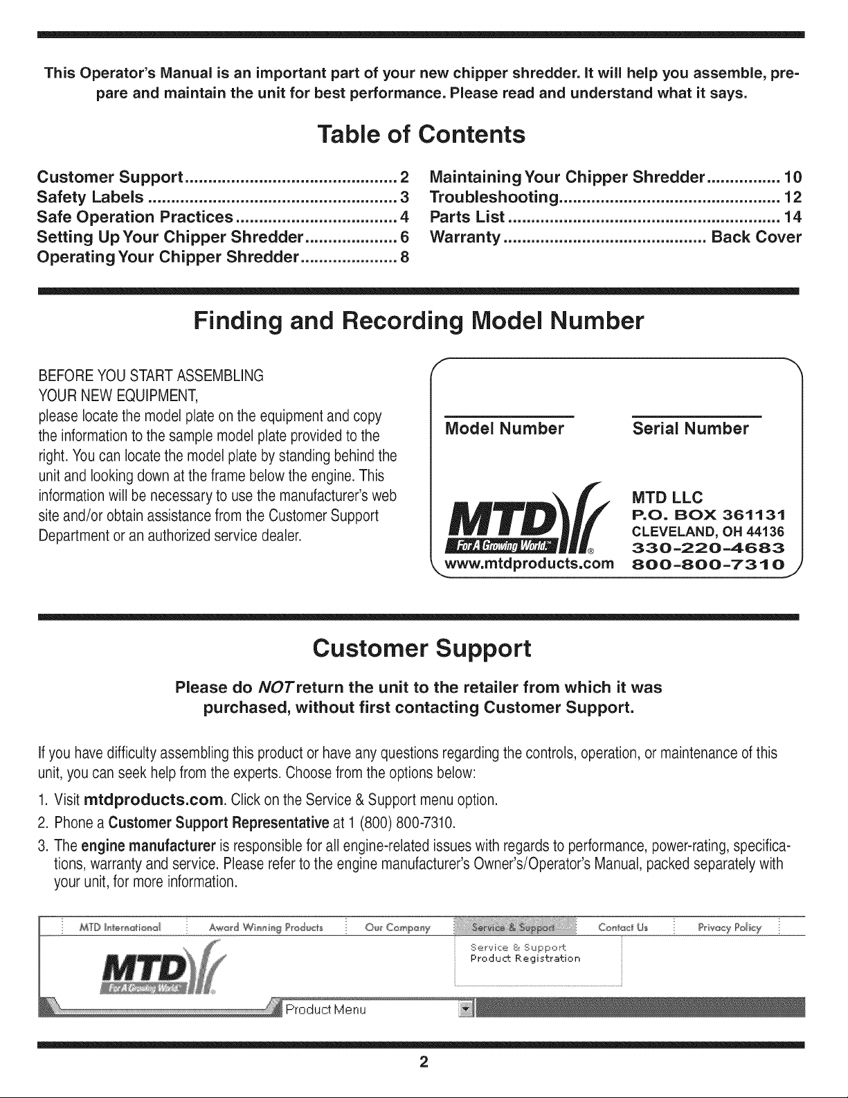
Finding and Recording Model Number
BEFOREYOUSTARTASSEMBLING
YOURNEW EQUIPMENT,
pleaselocate themodel plateon the equipment and copy
the informationto the sample model plate providedto the
right.Youcan locatethe modelplate by standing behindthe
unitand looking down at the frame belowtheengine. This
informationwill benecessary to usethe manufacturer'sweb
site and/or obtainassistancefrom the CustomerSupport
Departmentor an authorizedservice dealer.
Maintaining Your Chipper Shredder ................ 10
Troubleshooting ................................................ 12
Parts List ........................................................... 14
Warranty ............................................ Back Cover
f *x,
Model Number
Serial Number
MTD LLC
P.O. BOX 361131
CLEVELAND, OH 44136
®
www.mtdproducts,com
330 -220 -4683
800-800-7310
J
Customer Support
Please do NOTretum the unit to the retailer from which it was
purchased, without first contacting Customer Support.
Ifyou havedifficulty assembling this productor haveany questionsregarding the controls, operation, or maintenanceof this
unit,youcan seek helpfrom the experts. Choose from the options below:
1. Visit mtdproducts.com. Click on the Service& Support menu option.
2. Phonea Customer Support Representative at 1 (800) 800-7310.
3. Theengine manufacturer isresponsiblefor all engine-related issueswithregards to performance,power-rating,specifica-
tions,warrantyand service. Pleaserefer to the engine manufacturer'sOwner's/Operator'sManual, packedseparatelywith
your unit,for more information.
MTD Hin_r_oti®d A_wJ_d Wi_n i_g ?rod_t_ O'_r Comp_y
Ser,oqce & Suppo ±
Product. Registration
Con_@_z_Us
?rba_y Policy
2
Page 3
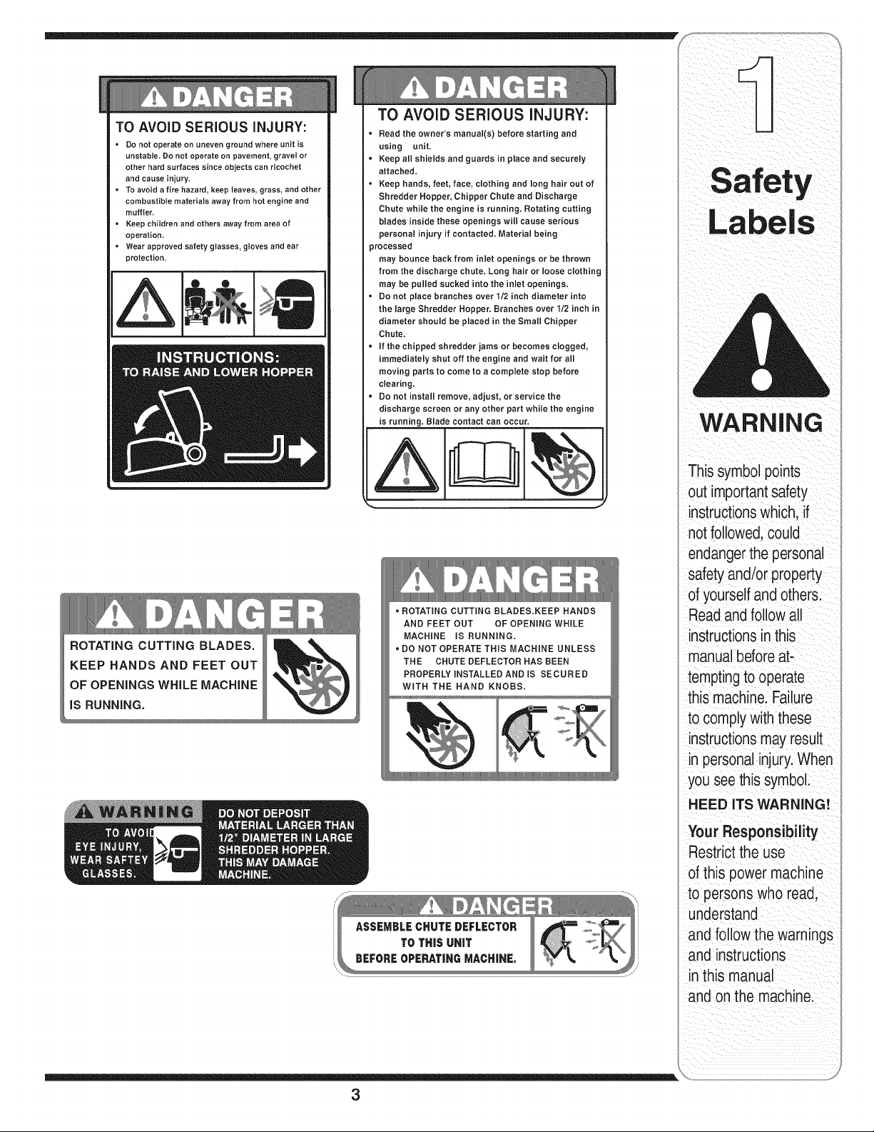
TO AVOID SERIOUS iNJURY:
• Do not operate on uneven ground where unit is
unstable, Do not operate on pavement, gravel or
other hard surfaces since objects can ricochet
and cause injury,
• To avoid a fire hazard, keep leaves, grass, and other
combustible materials away from hot engine and
muffler,
• Keep children and others away from area of
operation,
• Wear approved safety glasses, gloves and ear
protection.
ROTATING CUTTING BLADES.
KEEP HANDS AND FEET OUT
OF OPENINGS WHILE MACHINE
iS RUNNING.
TO AVOID SERIOUS iNJURY:
• Read the owner's manual(s) before starting and
using unit,
• Keep all shields and guards in place and securely
attached.
• Keep hands, feet, face, clothing and long hair out of
Shredder Hopper, Chipper Chute and Discharge
Chute while the engine is running, Rotating cutting
blades inside these openings will cause serious
personal injury if contacted. Material being
processed
may bounce back from inlet openings or be thrown
from the discharge chute. Long hair or loose clothing
may be pulled sucked into the inlet openings.
• Do not place branches over 1/2 inch diameter into
the large Shredder Hopper. Branches over 1/2 inch in
diameter should be placed in the Small Chipper
Chute.
• If the chipped shredder jams or becomes clogged,
immediately shut off the engine and wait for all
moving parts to come to a complete stop before
clearing.
• Do not install remove, adjust, or service the
discharge screen or any other part while the engine
is running. Blade contact can occur.
• ROTATING CUTTING BLADES.KEEP HANDS
AND FEET OUT OF OPENING WHILE
MACHINE iS RUNNING.
DO NOT OPERATE THiS MACHINE UNLESS
THE CHUTE DEFLECTOR HAS BEEN
PROPERLY iNSTALLED AND IS SECURED
WITH THE HAND KNOBS.
iil _I ii_ _ i _iii_!i _ _ii_ ii
WARNING
Thissymbolpoints
J
out importantsafety
instructionswhich,if
notfollowed,could
endangerthepersonal
safetyand/or property
of yourselfandothers.
Readandfollowall
instructionsinthis
manualbeforeat-
temptingto operate
this machine.Failure
to complywiththese
instructionsmayresult
in personalinjury.When
youseethis symbol.
HEED ITS WARNING!
Your Responsibility
Restrictthe use
ofthis power machine
to persons who read,
understand
and follow thewarnings
and instructions
in this manual
and onthe machine.
3
Page 4
WARNING: EngineExhaust,some of its constituents,andcertain vehicle compo-
nentscontain or emit chemicals knownto Stateof Californiato cause cancerand
birth defects or other reproductiveharm.
DANGER: This machinewas builtto beoperatedaccordingto the rulesfor safe operationin this
manual.As with anytypeof power equipment,carelessnessor error on the part of the operator can
result in seriousinjury.This machine iscapableof amputatinghands andfeet andthrowing objects.
Failureto observethe followingsafetyinstructionscould result in serious injury or death.
WARNING
Thissymbolpoints
out importantsafety
instructionswhich,if
notfollowed,could
endangerthe personal
i safetyand/or property
I ofyourselfandothers.
Readandfollowall
instructionsinthis
manualbeforeat-
temptingto operate
i this machine.Failure
I to complywiththese
instructionsmayresult
i inpersonalinjury.When
youseethis symbol.
i HEED ITS WARNING!
Your Responsibility
Restrictthe use
ofthis powermachine
to personswho read,
_understand
ane followthe warnings
and instructions
inthis manual
and on the machine.
Training
1. Read,understand,andfollowall instructionsonthe 1.
machineandin themanual(s)beforeattemptingto
assembleandoperate.Keepthis manualina safe placefor
futureandregularreferenceandfor orderingreplacement
parts. 2.
2. Befamiliarwithall controlsandtheirproperoperation.
Knowhowto stopthe machineanddisengagethemquickly.
3. Neverallowchildrenunder16yearsoldto operatethis
machine.Children16yearsoldandovershouldreadand
understandtheoperationinstructionsandsafetyrulesin 3.
thismanualand shouldbetrainedandsupervisedbya
parent.
4. Neverallowadultsto operatethis machinewithoutproper
instruction.
5. Keepbystanders,helpers,pets,andchildrenatleast75 4.
feetfromthe machinewhileit isin operation.Stop machine
ifanyoneentersthearea.
6. Neverrunanengineindoorsorina poorlyventilatedarea.
Engineexhaustcontainscarbonmonoxide,an odorless
anddeadlygas. 5.
7. Donot puthandsandfeet nearrotatingpartsor inthe
feedingchambersand dischargeopening.Contactwiththe 6.
rotatingimpellercanamputatefingers,hands,andfeet.
8. Neverattemptto unclogeitherthefeedintakeordischarge
opening,removeoremptybag, orinspectandrepairthe
machinewhiletheengineis running.Shuttheengineoff
andwaituntilallmovingparts havecometo acomplete
stop.Disconnectthe sparkplugwireandgroundit against
theengine.
Preparation
Thoroughlyinspecttheareawherethe equipmentisto
beused.Removeallrocks,bottles,cans,or otherforeign
objectswhichcouldbe pickeduporthrownandcause
personalinjuryor damageto the machine.
Alwayswearsafetyglassesorsafetygogglesduringopera-
tionor whileperforminganadjustmentor repair,to protect
eyes.Thrownobjectswhichricochetcancauseserious
injurytothe eyes.
Wearsturdy,rough-soledworkshoesand close-fitting
slacksandshirts. Loosefittingclothesor jewelrycan be
caughtinmovableparts.Neveroperatethis machine
in barefeet or sandals.Wearleatherworkgloveswhen
feedingmaterialin thechipperchute.
Beforestarting,checkallboltsandscrewsfor propertight-
nessto besurethemachineisin safeworkingcondition.
Also,visuallyinspectmachinefor anydamageatfrequent
intervals.
Maintainorreplacesafetyandinstructionslabels,as
necessary.
Toavoidpersonalinjuryor propertydamageuseextreme
careinhandlinggasoline.Gasolineisextremelyflammable
andthe vaporsare explosive.Seriouspersonalinjurycan
occurwhengasolineis spilledonyourselforyour clothes
whichcanignite.Washyour skinandchangeclothes
immediately.
a. Useonlyanapprovedgasolinecontainer.
b. Extinguishallcigarettes,cigars, pipes,andother
sourcesofignition.
c. Neverfuelmachineindoors.
d. Neverremovegascap oradd fuelwhilethe engineis hot
or running.
e. Allowengineto coolat leasttwo minutesbeforerefuel-
ing.
f. Neveroverfillfueltank. Filltankto nomorethan1/2
inchbelowbottomoffiller neckto providespaceforfuel
expansion.
g. Replacegasolinecap andtightensecurely.
h. If gasolineis spilled,wipe itoff theengineandequip-
ment.Movemachinetoanotherarea.Wait5 minutes
beforestartingtheengine.
i. Neverstorethe machineorfuel containerinsidewhere
there is an openflame,spark,or pilotlight (e.g.furnace,
waterheater,spaceheater,clothesdryer,etc.)
j. Toreducea fire hazard,keepmachinefreeofgrass,
leaves,orotherdebrisbuild-up.Cleanupoilor fuel
spillageandremoveanyfuel soakeddebris.
k. Allowmachinetocoolat least5 minutesbeforestoring.
4
Page 5
Operation
1. Donot puthandsandfeet nearrotatingpartsor in the
feedingchambersanddischargeopening.Contactwith the
rotatingimpellercanamputatefingers, hands,andfeet.
2. Beforestartingthemachine,makesurethechipperchute,
feedintake,andcuttingchamberare emptyandfree ofall
debris.
3. Thoroughlyinspectall materialto beshreddedand remove
any metal,rocks,bottles,cans,orotherforeignobjects
whichcouldcausepersonalinjuryordamageto the
machine.
14.f it becomesnecessaryto pushmaterialthroughthe
shredderhopper,usea smalldiameterstick. Do notuse
yourhandsorfeet.
15.fthe impellerstrikesa foreignobject or ifyourmachine
shouldstart makinganunusualnoiseor vibration,
immediatelyshuttheengineoff.Allowthe impellertocome
to a completestop.Disconnectthesparkplugwire,ground
itagainstthe engineandperformthefollowingsteps:
a. Inspectfordamage.
b. Repairorreplaceanydamagedparts.
c. Checkfor any loosepartsand tightento assure
continuedsafeoperation.
6. Donotallow an accumulationof processedmaterialtobuild
upinthedischargearea.Thiscan preventproperdischarge
andresult in kickbackof materialthroughthefeed opening.
7. Donotattemptto shredorchipmateriallargerthan
specifiedonthe machineor inthis manual.Personalinjury
or machinedamagecouldresult.
8. Neverattemptto unclogeitherthe feed intakeordischarge
openingwhilethe engineisrunning.Shutthe engineoff,
wait until all movingpartshavestopped,disconnectthe
sparkplugwireandgroundit againsttheenginebefore
clearingdebris.
9. Neveroperatewithouttheshredderhopper,chipperchute,
or chutedeflectorproperlyattachedto the machine.Never
emptyor changedischargebagwhiletheengineis running.
10.Keepall guards,deflectorsandsafetydevicesin placeand
operatingproperly.
11.Keepyourface andbodybackand totheside ofthechipper
chutewhilefeedingmaterialintothe machineto avoid
accidentalkickbackinjuries.
12.Neveroperatethis machinewithoutgoodvisibility or light.
13.Donotoperatethismachineon a paved,gravelor non-level
surface.
14.Donotoperatethismachinewhile undertheinfluenceof
alcoholordrugs.
15.Mufflerandenginebecomehotandcan causea burn.Do
nottouch.
16.Neverpickupor carrymachinewhilethe engineisrunning.
Maintenance & Storage
1. Nevertamperwithsafetydevices.Checktheirproper
operationregularly.
2. Checkbolts and screwsfor propertightnessatfrequent
intervalstokeepthe machineinsafeworkingcondition.
Also,visuallyinspectmachinefor anydamageandrepair,if
needed.
3. Beforecleaning,repairing,or inspecting,stoptheengine
andmakecertainthe impellerand all movingpartshave
stopped.Disconnectthesparkplugwireandgroundit
againsttheengineto preventunintendedstarting.
4. Do notchangetheenginegovernorsettingsor overspeed
theengine.The governorcontrolsthemaximumsafe
operatingspeedoftheengine.
5. Maintainor replacesafetyandinstructionlabels,as neces-
sary.
6. Followthis manualforsafeloading,unloading,transporting,
andstorageofthis machine.
7. Neverstorethe machineorfuel containerinsidewhere
thereisan openflame,sparkor pilot lightsuchasa water
heater,furnace,clothesdryer,etc.
8. Alwaysreferto theoperator'smanualfor properinstructions
onoff-seasonstorage.
9. If thefueltankhasto be drained,dothisoutdoors.
10.Observeproperdisposallawsandregulationsfor gas,oil,
etc.toprotecttheenvironment.
Do not modify engine
Toavoidseriousinjuryordeath,donot modifyengineinany
way.Tamperingwiththegovernorsettingcan leadto arunaway
engineandcauseit tooperateatunsafespeeds.Nevertamper
withfactorysettingofenginegovernor.
Notice regarding Emissions
Engineswhicharecertifiedto complywithCaliforniaandfederal
EPAemissionregulationsforSORE(SmallOff RoadEquipment)
arecertifiedtooperateonregularunleadedgasoline,andmay
includethefollowingemissioncontrolsystems:EngineModifica-
tion(EM)andThreeWayCatalyst(TWO)ifso equipped.
Your Responsibility
Restrictthe useofthispowermachineto personswhoread,un-
derstandandfollowthe warningsandinstructionsin this manual
andon the machine.
Operation
WARNING
Thissymbol points
out importantsafety
instructions,which if
notfollowed,could
endangerthe personal
safety and/or property
of yourself and others.
Readand followall
instructions inthis man-
ual before attemptingto
operatethis machine.
Failureto comply with
these instructionsmay
result in personalinjury.
Whenyou seethis
symbol.
HEED iT S WARNING!
YourResponsibility
Restrictthe use
of this powermachine
to personswho read.
understand
and followthe warnings
and instructions
in this manua
and on the machine.
5
Page 6
iMPORTANT
Thisunitisshipped
without gasolineor
oil inthe engine.Be
certainto service
enginewith gasoline
and oil as instructed
inthe separateengine
manual beforeoperat-
ingyour machine.
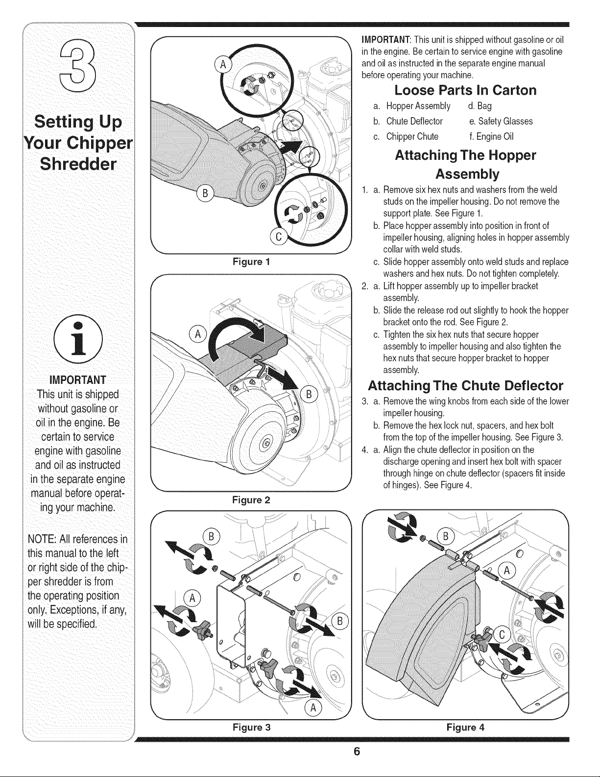
Figure 1
Figure 2
iMPORTANT:Thisunitisshippedwithoutgasolineoroil
in theengine.Becertainto serviceenginewithgasoline
andoilas instructedintheseparateenginemanual
beforeoperatingyourmachine.
Loose Parts In Carton
a. HopperAssembly d. Bag
b. ChuteDeflector e.SafetyGlasses
c. ChipperChute f. EngineOil
Attaching The Hopper
Assembly
1. a. Removesixhexnutsandwashersfromtheweld
studsontheimpellerhousing.Donotremovethe
supportplate.SeeFigure1.
b. Placehopperassemblyintopositioninfrontof
impellerhousing,aligningholesinhopperassembly
collarwithweldstuds.
c. Slidehopperassemblyontoweld studsandreplace
washersandhex nuts.Donottightencompletely.
2. a. Lift hopperassemblyupto impellerbracket
assembly.
b. Slidethereleaserodoutslightlyto hookthehopper
bracketontothe rod.SeeFigure2.
c. Tightenthe sixhexnutsthatsecurehopper
assemblytoimpellerhousingandalsotightenthe
hexnutsthatsecurehopperbrackettohopper
assembly.
Attaching The Chute Deflector
3. a. Removethewingknobsfromeachsideofthe lower
impellerhousing.
b. Removethe hexlocknut,spacers,andhexbolt
fromthetopoftheimpellerhousing.SeeFigure3.
4. a. Alignthechutedeflectorin positiononthe
dischargeopeningandinserthexboltwithspacer
throughhingeonchutedeflector(spacersfit inside
ofhinges).See Figure4.
NOTE:All referencesin
this manualto the left
or rightside ofthe chip-
per shredderis from
theoperating position
only.Exceptions.ifany,
will be specified.
j {
/j /'
Figure 3
Figure 4
6
Page 7

b. Placesecondspaceroverhex boltinsideother
hingeandsecurewithhexlocknut.
c. Securebothsidesofchutedeflectorto impeller
housingusingwingknobspreviouslyremoved.
Attaching The Chipper Chute
5. a. Removethethreecuppedwashersandhexnuts
fromweldstudsaroundtheopeningonthesideof
theimpellerhousing.SeeFigure5.
b. Removethehexbolts,flat washers,andlocknuts
fromthetwoholeson the upperendofthesupport
brace.
6. a. Alignthechipperchuteovertheweldstuds,sothe
slotinthebottomof thechuteisfacingdown.
b. Securechipperchutewiththe threecupped
washers(cuppedsideagainstthe chipperchute)
and hexnutspreviouslyremoved.Donottighten
thenutsatthistime. SeeFigure6.
7. The chippershredderwasshippedwithoneendof
thesupportbracealreadysecuredtothe lowerframe.
Loosenbutdo notremovetheboltssecuringthebrace
totheframe.SeeFigure7.
a. Aligntheholesin thechutewiththe holesinthetop
ofthebraceandattachbracetochipperchutewith
hardwarepreviouslyremoved.Tightensecurely.
b. Tightenthe boltssecuringthesupportbracetothe
frame.
c. Tightenthethreenutsontheweldstudsholding
thechipperchutetotheimpellerhousing.
Attaching The Bag
8. Toattachthe bag:
a. Placetheopeningof thebagcompletelyoverthe
chutedeflector.
b. Pullon the drawstringuntilthebagistightaround
chutedeflectoropening.
c. Clipdrawstringbackon itself,tightagainstchute
deflectorto secureintoposition.SeeFigure8.
Your Chipper
Shredder
.//
Figure 5
f
Figure 6
i
/
i
i
/
/
/
/
/
/
/
/
i /
/ /
/
/
/
/
/
/
/
ii i _iI_ ii
J
Figure 8 Figure 7
7
i
i
i s
/
/
/
Page 8

WARNING
The operation of any
chippershredder
can result inforeign
objects being thrown
intothe eyes,which
can damageyour
I eyes severely.Always
i wear the safety
glasses provided
with this unit or eye
i shields before chip-
pingor shredding
and while performing
i any adjustmentsor
repairs.
I Use extreme care
when handling
gasoline.Gasolineis
i extremelyflammable
and the vaporsare
explosive. Never fuel
i the machine indoors
or while the engine
is hot or running.
; Extinguishcigarettes,
cigars, pipes and
other sources of
i ignition.
Know Your Chipper Shredder
HopperAssembly
ReleaseRod
Oil Fill1-
Chipper
TowBart'_
Now that you have set up your chipper shredder
for operation, get aquainted with its controls and
features. These are described below and illustrated
on this page. This knowledge will allow you to use
your new equipment to its fullest potential.
Chipper Chute
Allows twigs and small branches up to 3" in diam-
eter to be fed into the impeller for chipping. See
Figure 9.
Hopper Assembly
Allow leaves and small branches up to 1/2 diameter
to be fed into the impeller for chipping and shred-
ding. Material can be raked into hopper assembly
by lowering the hopper assembly. See Figure 9.
Release Rod
The release rod is located on the impeller bracket
assembly and it is used to release or lock the hop-
per when raising or lowering. See Figure 9.
Tow Bar (if Equipped)
Use the tow bar to tow the chipper shredder behind
a tractor to a job site. See Figure 9.
NOTE:Ifyourunitisnotequippedwithatowbar,you
maycontactCustomerSupportasinstructedonpage2
forinformationregardingpriceandavailability.
Oil Fill
@
1-If Equipped
Figure 9
Gas and Oil Fill-Up
1. Check oil level and add oil if necessary. Follow engine
manual for this. See Figure 9 above for location of the
oil fill.
2. Servicethe enginewithgasolineasinstructedinthe
enginemanual. SeeFigure9 aboveforlocationof
gas fill.
WARNING:Useextremecarewhen han-
dling gasoline.Gasolineisextremely
flammableand the vapors areexplosive.
Neverfuel the machine indoorsor while
the engineis hotor running. Extinguish
cigarettes,cigars,pipesandother
sourcesof ignition.
WARNING:Theoperation of any
chippershreddercanresultinforeign
objectsbeingthrown intothe eyes,
which candamage youreyesse-
verely.Alwayswearthe safetyglasses
providedwith this unit or eyeshields
before chippingor shreddingandwhile
performingany adjustments or repairs.
8
Page 9

Starting Engine
_hlk ARNING:Neverrun the engine
1. Attachsparkplugwiretosparkplug.Makecertain
themetalcapontheend ofthe sparkplugisfastened
securelyoverthemetaltiponthe sparkplug.
2. Engines with choke lever:
Movechokeleveronengineto CHOKEposition.(A
warmenginemaynotrequirechoking).
Engineswith primer:
Primeengineasinstructedinseparateenginemanual.
3. The throttlecontrolleverislocatedontheengine.
MoveenginethrottlecontrollevertoFASTor START
position.SeeFigure10.
4. Graspstarterhandleand pullropeoutslowlyuntil
enginereachesstartofcompressioncycle(ropewill
pull slightlyharderatthispoint).
NOTE:A noisewillbeheardwhenfindingthestartof
thecompressioncycle.Thisnoiseis causedbytheflails
andfingers,whichare partoftheshreddingmechanism,
and itshouldbeexpecteduntilthe impellerreachesfull
speed.
indoorsor in a poorly ventilatedarea.
Engineexhaustcontainscarbonmonox-
ide,an odorlessand deadly gas.
Figure 10
Using The Chipper Shredder
Yardwastesuchas leavesandpineneedlescanbe
rakedupthroughthehopperassemblyforshredding.
Aftermaterialhasbeenshreddedbytheflail bladeson
theimpellerassembly,itwillbe dischargedoutofopen-
ingorintocatcherbag.Donotattemptto shredorchip
anymaterialotherthanvegetationfoundina normal
yard(i.e.branches,leaves,twigs,etc.)Avoidfibrous
plantssuchastomatovinesuntiltheyarethoroughly
driedout. Twigsandsmallbranchesupto3" in diameter
canbefedintothechipperchute.
Lowering The Hopper Assembly
1. Withonehandgraspthehandleatthetopofthe
hopperassemblyandliftslightly.
2. Withtheotherhandpulloutonthe releaserod
andlowerthehopperassemblytotheground.See
Figure9.
WARNING
Never run the engine
indoorsorin a poorly
ventilated area: Engine
exhaust contains
carbon monoxide, an
_dorless and deadly
5. Pullropewitha rapid,continuous,fullarmstroke.
Keepa firmgriponstarterhandle.Let roperewind
slowly.
6. Repeatthepreviousstepsuntilenginefires.When
enginestarts,movechokecontrol(ifequipped)
graduallyto RUNposition.
Stopping Engine
1. Movethrottlecontrolleverto STOPorOFFposition.
2. Disconnectsparkplugwirefromsparkplugand
groundagainsttheengine.
NOTE:Seeyourenginemanualpackedwithyourunitfor
moredetailedinstructions.
To Empty Bag
1. Un-clipdrawstringand loosenbagfromchute
deflectoropening.
2. Emptybagandreattachtothe dischargechute
opening.Pullonthedrawstringuntilthebagistight
aroundthechuteopeningandclipthedrawstring
tightagainstthechutedeflector.
IMPORTANT:Theflailscreenislocatedinsidethe
housinginthedischargearea.If theflail screen
becomesclogged,removeandcleanasinstructedin
SECTION5: MAINTAININGYOURCHIPPERSHRED-
DER.Forbestperformance,it isalsoimportantto keep
thechipperbladesharp.
NOTE: A noisewillbe
heardwhenfindingthestart
ofthe compressioncycle.
Thisnoiseiscausedby
theflailsand fingers,which
arepartoftheshredding
mechanismanditshould
oeexpecteduntilthe impel-
er reachesfullspeed.
9
Page 10

WARNING
Alwaysstop engine,
isconnect spark plug,
groundagainst
pnginebeforecleaning,
lubricating or doing any
Kind of maintenance on
yourmachine.
points before
reassembly.
Figure 11
i
/
Figure 12
General Recommendations
1. Alwaysobservesafetyruleswhen performing
anymaintenance.
2. Thewarrantyonthischippershredderdoesnot
coveritemsthathavebeensubjectedtooperator
abuseornegligence.Toreceivefullvaluefromwar-
ranty,operatormustmaintainthechippershredder
asinstructedhere.
3. Changingofengine-governedspeedwillvoid
enginewarranty.
4. Alladjustmentsshouldbecheckedat leastonce
eachseason.
5. Periodicallycheckallfastenersand makesurethese
aretight.
_ ARNING:Alwaysstopengine,
disconnect sparkplug, and ground
against enginebeforecleaning,
lubricating or doing any kind of
maintenanceon yourmachine.
/
/
/
/ "
/"
Lubrication
1. Lubricatethereleaserodand springwithlightoil once
a season.SeeFigure11.
2. Lubricatethepivotpointsonthehopperassemblywith
lightoil onceaseason.See Figure11.
3. Lubricatethepivotpointsonthedischargechutewith
lightoil onceaseason.See Figure11.
4. Followtheaccompanyingenginemanualforlubrica-
tionscheduleandinstructionforenginelubrication.
Engine Care
1. Maintainoillevelasinstructedin enginemanual.
2. Serviceaircleanerevery25hoursundernormal
conditions.Cleaneveryfewhoursunderextremely
dustyconditions.Refertoenginemanual.
3. Cleansparkplugandresetthegaponcea season.
Checkenginemanualforcorrectplugtypeandgap
specifications.
4. Cleanengineregularlywitha clothorbrush.Keepthe
coolingsystem(blowerhousingarea)cleantopermit
properaircirculation.Removeall grass,dirtand
combustibledebrisfrommufflerarea.
Removing The Flail Screen
If thedischargeareabecomesclogged,removetheflail
screenandcleanareaasfollows:
1. Stoptheengineandmakecertainthechippershred-
derhascometoa completestop.
2. Disconnectsparkplugwirefromsparkplugand
groundagainsttheengine.
3. a. Removethebagandtwo wingknobson eachside
ofthechutedeflector.SeeFigure12.
b. Liftthechutedeflectorupto keepitoutof theway.
c. Removethetwo hairpinclipsfromeachclevispin
whichextendthroughthe housingandremovepins.
d. Removetheflail screenfrominsidethehousing
andcleanthescreenbyscrapingor washingwith
water.SeeFigure12.
4. Reinstallthescreen,makingcertainto reassemblethe
flailscreenwiththecurvesidedown.
5. Reattachthechutedeflectorwiththehardware
previouslyremovedandconnectthe bagtounit.
Sharpening Or Replacing Chipper
Blades
1. Disconnectthesparkplugwireandgroundagainstthe
engine.
2. Removetheflail screenasinstructedintheprevious
section.
3. Removethechipperchutebyremovingthreehexnuts
andwashers.
4. Removethechipperchutesupportbracefromthe
framebyremovingthehexbolts.
5. Rotatetheimpellerassemblybyhanduntilyoulocate
oneofthetwochipperbladesin thechipperchute
opening.
10
Page 11

6. Removethebladebyremovingthe internalhex
screws,lockwashers,andhexnutswhichsecureitto
theimpeller.Retainthehardware.SeeFigure13.
NOTE:Usea 3/16"hex key(Allen)wrenchontheoutside
ofthebladeanda1/2"box(or socket)wrenchonthe
insideof theimpeller.HoldtheAllenwrenchstationary
and rotatethebox(orsocket)wrenchto loosenthenut.
7. Installa replacementblade(PartNo.781-0490)with
thehardwareremovedearlierorsharpen.
IMPORTANT:Whensharpeningtheblade,protecthands
byusinggloves.Followtheoriginalangleof grindand
makesuretoremoveanequalamountfromeachblade.
8. To replacetheotherblade,rotatetheimpellerto
exposethesecondbladeandrepeatthestepsabove.
NOTE: Makecertainbladesarereassembledwiththe
sharpedgefacingupward.Torquehardwareto250- 300
in.Ibs.
Sharpening Or Replacing The
Shredder Blade
Figure 13
WARi ,,ING
The impeller S
chipper blades and
shredder blade are
_ ARNING:Theimpeller'schipperblades
__ protectyour hands.
1. Stop theengineand makecertainthatall moving
partshavecometoacompletestop.
2. Disconnectthesparkplugwireandgroundagainstthe
engine.
3. Lowerthehopperassemblyandblockupthehousing.
4. Removethesixhexlocknutsandflatwashers
fromtheweldstudson theflail housing.Retainthe
hardware.
5. Carefullyseparatethehopperassemblyfromthe
impellerassemblyandremovethesupportplate.
NOTE:When reassemblingthe supportplate,make
certaintheembossedtabfacesinwardtowardsthe
impeller.
6. Removethetwowingknobsandcuppedwashersthat
securethechutedeflectorandraisethechute.
7. Inserta 1/2"or 3/4"diameterpipethroughtheflail
screenintotheimpellertokeepit fromturningor
removetheflailscreenandinsertapieceofwoodinto
thechuteopening.
8. a. Removethetwointernalhexscrews,lockwashers,
b. Removethehexbolt,lockwasher,andflatwasher
are sharp. Wearleather work gloves to
and hexlocknutswhichsecuretheshredderblade
totheimpeller.
tocompletelyfreeshredderblade.SeeFigure14.
Figure 14
NOTE:Usea3/16"hexkey(Allen)wrenchonthe
outsideoftheshredderbladeanda 1/2"box(orsocket)
wrenchontheinsideoftheshredderblade.Holdthe
Allenwrenchstationaryandrotatethebox(orsocket)
wrenchtoloosenthenut. Usecautionwhenremoving
thebladetoavoidcontactingtheweldstudsonhousing.
IMPORTANT:Whensharpeningthe blade,follow
theoriginalangleofgrindasa guide.It is extremely
importantthateachcuttingedgereceivesanequal
amountofgrindingtopreventanunbalancedblade.
Anunbalancedbladewillcauseexcessivevibration
whenrotatingat highspeedsandmaycausedamage
totheunit.Thebladecanbetestedbybalancingit on a
screwdriveror nail.Removemetalfromtheheavyside
untilitisbalancedevenly.
Storing Your Chipper Shredder
Thefollowingstepsshouldbetakento prepareyour
chippershredderforstorage.
1. Cleantheequipmentthoroughly.
2. Wipeequipmentwithanoiledragto preventrust.
3. Referto enginemanualforcorrectenginestorage
instructions.
4. Storeunitina clean,dryarea. Donot storenextto
corrosivematerialssuchasfertilizer.
work gloves to
protect your hands:
IMPORTANT
Makecertain chipper
bladesare reassem-
bledwith the sharp
edgefacing upward.
Torquehardwareto
250- 300 in. Ibs.
iMPORTANT
When reassemblingthe
shredderblade, tighten
center boltto between
550 and 700 in.-Ibs.
andthe two out bolts to
between250 and 350
in.-Ibs.
11
Page 12

Forrepairs beyond
the minor adjustments
listed here, contact
an authorized service
Problem Cause Remedy
En_in f_il rf I 1 Throtte evernot n correctstartng 1 Movethrotte everto FASTor
= e _ stosta,
position(ifequipped). STARTposition,
2. Sparkplugwiredisconnected, 2. Connectwireto sparkplug.
3. Chokenot inCHOKEposition(if 3. Movechokeleverto CHOKE
equipped), position.
4. Fueltankemptyorstalefuel. 4. Filltankwithclean,freshgasoline.
5. Enginenot primed(ifequipped). 5. Primeengineas nstructedin
EngineManual.
6. Fauty sparkpug. 6. C can adjustgap or repace.
7, Blockedfuelline. I 7. Cleanfuelline.
8. Engineflooded. 8. Waitafew mnutestorestart,but
Engineruns erratic 1, Sparkplugwireloose, 1, Connectandtightenspark
2, UnitrunningonCHOKE(ifequipped), 2, Movechokeleverto OFFposition,
3. Blockedfuellineorstalefuel. 3. Cleanfuelline;filltankwithclean,
4. Ventingascapplugged. 4. Clearvent.
5. Waterordirt infuelsystem. 5. Drainfueltank.Refillwith
6. Dirty aircleaner. 6. Referto enginemanual.
7. Carburetorout ofadjustment. 7. Seeauthorizedservicedealer.
do notprime.
plugwire,
freshgasoline.
freshfuel.
Engineoverheats 1. Engineoil levellow. 1. Fillcrankcasewithproperoil.
2 Drtyarceaner I 2 Refertoengnemanua
I
• 3. Carburetornotadjustedproperly. " 3. Seeauthorizedservicedealer.
Occasionalskips 1. Sparkpluggaptooclose. 1. Adjustgap to .030".
(hesitates)at 2. Carburetoridlemixtureadjustment 2. Seeauthorizedservicedealer.
highspeed improperlyset.
N m
Excessive I 1. Loosepartsordamagedimpeler I 1 Seeauthorzedservcedeeer
Vibration I I
Unit does not 1. Chutedeflectorclogged. 1. Stop engineimmediatelyand
discharge disconnectsparkplugwire.Clean
flailscreenandinsideofdischarge
opening.
2. Foreignobjectlodgedin impeller. 2. Stop engineanddisconnectspark
plugwire.Removelodgedobject.
3. LowengineRPM. 3. Alwaysrunengineatfullthrottle.
Rateof discharge 1 LowengineRPM. 1. Alwaysrunengineatfullthrottle.
slowsconsiderably I 2. Chipperbladedul. I 2. Replacechipperbladeor seeyour
or composition of authorzedservcedeeer.
changes ,
12
Page 13

_ii ii i_ __ _ i iiiiii ii ii ii_i _ i
usethispagetomake
notes and write down
important information,
13
Page 14

odel Series 462 Thru 464
- ' .._ .,q8;
14
Page 15

1. 736-0217 LockWasher,3/8
2. 714-0149B CotterPin
3. 681-0048 WingKnob5/16-18
4. 681-0094 ChuteDeflectorAssembly
5. 711-0835 ClevisPin
6. 781-0457 ShredderScreen
7. 726-0211 U-Nut5/16-18
8. _ 750-0793 _ Spacer
9. 712-3027 HexLockNut1/4-20
10. 712-3004A HexLockNut5/16-18
11. 736-0119 LockWasher5/16
12. 681-0117 InnerImpellerHousingAssembly
13. 710-3025 HexCapScrew5/16-18x.625
14. 710-0157 HexCapScrew5/16-24x.75
15. 781-0490 ChipperBlade
16. 710-1054 HexCapScrew5/16-24x 1.0
17. 681-0030 impellerAssembly
18. 712-0411 HexLockNut5/16-24
19. 781-0735 RetainerPinClip
20. 719-0329 FlailBlade
21. 711-0833B ClevisPin
22. 715-0166 Pin
23. 736-0247 FlatWasher3/8 x 1.25
24. 742-0571 ShredderBlade
25. 710-1254 HexCapScrew3/8-24x 2.25
26. 681-0004A OuterImpellerHousingAssembly
27. 710-0825 HexCapScrew1/4-20x 3.75
28. 781-0515 FrontSupportBracket
29. 781-0574 ShredderPlate
Toorder replacement
parts, contact
1=800-800-7310or visit
www.mtdproducts.com.
30. 681-0104 RearHopperBracketAssembly
31. 732-0306 CompressionSpring1.75
32. 736-0117 FlatWasher
33. 714-0104 CotterPin
34. 736-0264 FiatWasher.330IDx.630OD
35. 710-0376 HexCapScrew5/16-18x 1.0
36. 748-0453 Spacer,.375IDx 2.50LG
37. 736-0362 FiatWasher.320IDx 1.25OD
38. 712-0429 HexLockNut5/16-18
39. 731-1710 HopperCollar
40. 681-0123 FrontHopperBracketAssembly
41. 711-1128 LockRod
42. 731-1707 HopperAssembly
43. 710-3008 HexCapScrew5/16-18x.75
15
Page 16

odel Series 462 Thru 464
16
1 ModelSeries464
11 Model464GOnly
ModelSeries462
^ Models462&464D
* If Equipped
Page 17

1. 728-0175 PopRivet
2. 731-1899 ChipperShredderChute
3. 735-0249 ChuteFlap
4. 781-0633 ChuteFlapStrip
5. 681-0068A ChipperChuteAssembly
6. 710-0751 HexCapScrew1/4-20x.620
7. 712-3027 HexLockNut1/4-20
8. _ 710-0106 HexCapScrew1/4-20x 1.25
9. 736-0173 FiatWasher.28IDx.74OD
10. 736-0242 BellWasher.340IDx.872OD
11. 712-3010 HexNut5/16-18
12. 749-1004 SupportBrace
13. 712-3004A HexLockNut5/16-18
14. 710-0805 HexCapScrew5/16-18x 1.50
710-3180tt HexCapScrew5/16-18x 1.75
15. 736-0170 BellWasher5/16x 1.0
16. 736-0366t FlatWasher
17. 738-0814_1 AxleAssembly
738-0813t AxleAssembly
18. 750-0786_: Spacer
19. 734-1600:_ WheelComp.,10.0x2.5 Plastic
734-1845t WheelComplete,10.0x4.0 Gray
20. 726-0214 PushCap
21. 681-0184A Frame
681-0183Att Frame
22. 736-0451 Washer,.320IDx.93OD
23. 710-0502A Screw,3/8-16x 1.250
24. 737-0195A ElbowFitting
25. 737-0298tt Oil DrainPipe
26. 737-0132tt Oil DrainEndCap
27. 681-0133" TongueHitchMount
28. 681-0134A* BaseHitchMount
29. 710-3001" HexCapScrew,3/8-16x.88
30. 711-0299" ClevisPin,.625x 2.4
31. 711-0835" ClevisPin,.50x 4.62
32. 712-3017" HexNut,3/8-16
33. 732-0194" SpringPin
34. 736-0133" FiatWasher,.411x 1.25x1.0
35. 736-0169" LockWasher,3/8
-- 723-0400 SafetyGlasses(NotShown)
k
-- 664-04022 ChipperBagAss'y(Not Shown)
-- 664-04023tt ChipperBagAss'y(NotShown)
t ModelSeries464 AModels462& 464D
tt Model464GOnly * IfEquipped
_1ModelSeries462
Toorder replacement
parts, contact
1-800-800-7310 or visit
www.mtdproducts.com.
17
Page 18

Use this page to make
notes and write down
important information:
18
Page 19

notes and write down
important information:
19
Page 20

MANUFACTURER'S LiMiTED WARRANTY FOR
ThelimitedwarrantysetforthbelowisgivenbyMTDLLCwithrespectto
newmerchandisepurchasedandusedin theUnitedStates,itsposses-
sionsandterritories.
"MTD"warrantsthisproductagainstdefectsin materialandworkmanship
fora periodoftwo(2)yearscommencingonthe dateof originalpurchase
andwill,atits option,repairor replace,freeof charge,anypartfoundto
bedefectiveinmaterialsor workmanship.Thislimitedwarrantyshallonly
applyif this producthasbeenoperatedandmaintainedinaccordance
withtheOperator'sManualfurnishedwiththeproduct,andhasnotbeen
subjectto misuse,abuse,commercialuse,neglect,accident,improper
maintenance,alteration,vandalism,theft,fire,water,ordamagebecause
ofotherperilornaturaldisaster.Damageresultingfromtheinstallationor
useof anypart,accessoryorattachmentnotapprovedbyMTDforuse
withtheproduct(s)coveredbythis manualwillvoidyourwarrantyasto
anyresultingdamage.
Normalwearpartsarewarrantedto befreefromdefectsinmaterialand
workmanshipfora periodofthirty(30)daysfromthedateof purchase.
Normalwearpartsinclude,butarenotlimitedto itemssuchas:batteries,
belts,blades,bladeadapters,grassbags,riderdeckwheels,seats,snow
throwerskidshoes,shaveplates,augerspiralrubberandtires.
HOW TO OBTAIN SERVICE: Warrantyservice isavailable,WITH
PROOFOF PURCHASE,throughyour localauthorized service
dealer.Tolocatethe dealer in yourarea, check yourYellowPages, or
contact MTD LLC at RO. Box 361131,Cleveland,Ohio44136-0019,or
call 1-800-800-7310or 1-330-220-4683or log on to our Web site at
www.mtdproducts.com.
Thislimitedwarrantydoesnot providecoverageinthefollowingcases:
a. Theengineor componentpartsthereof.Theseitemsmaycarrya
separatemanufacturer'swarranty.Refertoapplicablemanufacturer's
warrantyfortermsandconditions.
b. Logsplitterpumps,valves,andcylindershavea separateoneyear
warranty.
c. Routinemaintenanceitemssuchas lubricants,filters,blade
sharpening,tune-ups,brakeadjustments,clutchadjustments,deck
adjustments,andnormaldeteriorationoftheexteriorfinishduetouse
orexposure.
d. Servicecompletedbysomeoneotherthananauthorizedservice
dealer.
e. MTDdoesnotextendanywarrantyforproductssoldorexported
outsideofthe UnitedStates,itspossessionsandterritories,except
thosesoldthroughMTD'sauthorizedchannelsofexportdistribution.
f. ReplacementpartsthatarenotgenuineMTDparts.
g. Transportationchargesandservicecalls.
No impliedwarranty,includinganyimpliedwarranty of merchant-
ability of fitness for a particularpurpose,applies afterthe applicable
periodof expresswritten warranty above as to the partsas identi-
fied. Noother expresswarranty, whether written or oral, exceptas
mentionedabove,givenby anypersonor entity,includinga dealer
or retailer,with respect to anyproduct,shallbind MTD.Duringthe
periodof the warranty, the exclusive remedyisrepairor replacement
of the productas set forth above.
Theprovisionsas set forth inthis warranty providethe sole and
exclusive remedyarising from the sale. MTDshall not beliable
for incidentalorconsequential loss or damageincluding,without
limitation, expensesincurredfor substitute orreplacementlawncare
services or for rentalexpensesto temporarily replaceawarranted
product.
Somestatesdo not allowtheexclusionor limitationofincidentalor
consequentialdamages,or limitationson howlonganimpliedwarranty
lasts,sotheaboveexclusionsor limitationsmaynotapplytoyou.
Innoeventshallrecoveryofany kindbegreaterthantheamountof the
purchasepriceof theproductsold.Alterationof safetyfeatures of the
productshall void this warranty. Youassumetheriskandliabilityfor
loss,damage,orinjurytoyouandyourpropertyand/ortoothersandtheir
propertyarisingout ofthemisuseor inabilitytousetheproduct.
Thislimitedwarrantyshallnotextendto anyoneotherthantheoriginal
purchaseror tothepersonforwhomitwaspurchasedasa gift.
HOWSTATELAWRELATESTOTHISWARRANTY: Thislimitedwar-
rantygivesyouspecificlegalrights,andyou mayalsohaveotherrights
whichvaryfromstatetostate.
IMPORTANT:OwnermustpresentOriginalProofofPurchasetoobtain
warrantycoverage.
MTD LLC, P.O. BOX 361131 CLEVELAND, OHIO 44136-0019; Phone: 1-800-800-7310, 1-330-220-4683
 Loading...