

Page 1
Operator's Manual
I(RRFTSMRW I
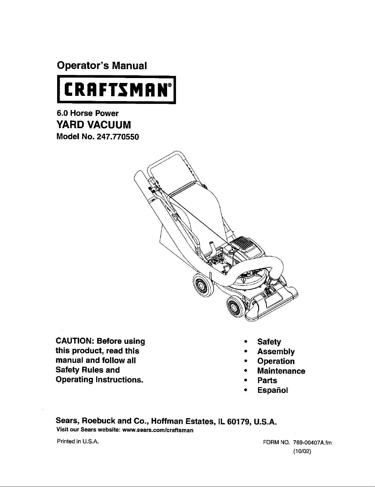
6.0 Horse Power
YARD VACUUM
Model No. 247.770550
CAUTION: Before using
this product, read this
manual and follow all
Safety Rules and
Operating Instructions.
Sears, Roebuck and Co., Hoffman Estates, IL 60179, U.S.A.
Visit our Sears website: www.sears.com/craftsman
Printed in U.S.A.
• Safety
• Assembly
• Operation
• Maintenance
• Parts
• Espa_ol
FORM NO. 769-00407A.fm
(10/02)
Page 2
Content Page Content Page
Warranty 2 Service and Adjustments 14
Safety 3 Storage 16
Assembly 5 Troubleshooting 17
Operation 8 Parts List 18
Maintenance 12
Limited Warranty on Craftsman Yard Vacuum
For one (1) year from the date of purchase, if this Craftsman Equipment is maintained, lubricated, and tuned up
according tothe instructions tothe operator's manual, Sears will repair or replace free of charge any parts found
to be defective in material or workmanship. Warranty service isavailable free of charge by returning Craftsman
equipment to your nearest Sears Service Center. In-home warranty service is available but a trip charge will
apply. This Warranty applies only while this product isin the United States.
This Warranty does not cover:
Expendable items which become worn during normal use, such as spark plugs, air cleaners, belts, and oil
filters.
• Tire replacement or repair caused by punctures from outside objects, such as nails, thorns, stumps, or glass.
Repairs necessary because of operator abuse, including but not limited to, damage caused by objects, such
as stones or metal debris, oversized stock, impacting objects that bend the frame or crankshaft, or over-
speeding the engine.
Repairs necessary because of operator negligence, including but not limited to, electrical and mechanical
damage caused by improper storage, failure to use the proper grade and amount of engine oil, or failure to
maintain the equipment according to the instructions contained in the operator's manual.
Engine (fuel system) cleaning or repairs caused by fuel determine to be contaminated or oxidized (stale). tn
general, fuel should be used within 30 days of its purchase date.
Equipment used for commercial or rental purposes.
TO LOCATE THE NEAREST SEARS SERVICE CENTER OR TO SCHEDULE SERVICE, SIMPLY CONTACT
SEARS AT 1-800-4-MY-HOME.
This warranty gives you specific legal rights and you may also have other rights, which vary from state to state.
PRODUCT SPECIFICATION
Horsepower:
Engine Oil Type
Engine Oil Capacity
FuelCapacity:
Spark Plug
Spark Plug Gap
6.0 Horse Power
SAE30
20 Ounces
1 1/2 Quarts
Champion RJ-19LM
.030"
Model Number ....... ,2.,4.,7.._'_,7.,.0.5_.0............................
Serial Number ...........................................................
Date of Purchase ......................................................
Reoord both serial number and date of purchase and
keep in a safe place for future reference,
Page 3
WARNING: This symbol points out important safety instructions which, if not followed, could
endanger the personal safety and/or property of yourself and others. Read and follow all
instructions in this manual before attempting to operate this machine. Failure to comply with these
instructions may result in personal injury. When you see this symbol - heed its warning.
WARNING: Engine Exhaust, some of its constituents, and certain vehicle
components contain or emit chemicals known to State of California to cause cancer
and birth defects or other reproductive harm.
DANGER: This machine was built to be operated according to the rulesfor safe operation inthis
manual.As withany type ofpowerequipment,carelessnessor erroron the partofthe operatorcan
resultinseriousinjury.Thismachineiscapableof amputatinghandsand feet andthrowingobjects.
Failuretoobservethe following safetyinstructionscouldresultinseriousinjuryordeath.
TRAINING
1. Read, understand, and follow all instructions on
the machine and in the manual(s) before
attempting to assemble and operate. Keep this
manual in a safe place for future and regular
reference and for ordering replacement parts.
2. Be familiar with all controls and their proper
operation. Know how to stop the machine and
disengage them quickly.
3. Never allow children under 16 years old to
operate this machine. Children 16 years old and
over should read and understand the operation
instructions and safety rules in this manual and
should be trained and supervised by a parent.
4. Never allow adults to operate this machine
without proper instruction.
5. Keep bystanders, helpers, pets, and children at
least 75 feet from the machine while it is in
operation. Stop machine if anyone enters the
area.
6. Never run an engine indoors or in a poorly
ventilated area. Engine exhaust contains carbon
monoxide, an odorless and deadly gas.
7. Do not put hands and feet near rotating parts or in
the feeding chambers and discharge opening.
Contact with the rotating impeller can amputate
fingers, hands, and feet.
8. Never attempt to unclog either the feed intake or
discharge opening, remove or empty vacuum
bag, or inspect and repair the machine while the
engine is running. Shut the engine off and wait
until all moving parts have come to a complete
stop. Disconnect the spark plug wire and ground
it against the engine.
PREPARATION
1. Thoroughly inspect the area where the
equipment is to be used. Remove all rocks,
bottles, cans, or other foreign objects which could
be picked up or thrown and cause personal injury
or damage to the machine.
2.
Always wear safety glasses or safety goggles
during operation or while performing an
adjustment or repair, to protect eyes. Thrown
objects which ricochet can cause serious injury to
the eyes.
3,
Wear sturdy, rough-soled work shoes and close-
fitting slacks and shirts. Loose fitting clothes or
jewelry can be caught in movable parts. Never
operate this machine in bare feet or sandals.
Wear leather work gloves when feeding material
in the chipper chute.
4.
Before starting, check all bolts and screws for
proper tightness to be sure the machine is in safe
working condition. Also, visually inspect machine
for any damage at frequent intervals.
5.
Maintain or replace safety and instructions labels,
as necessary.
6.
To avoid personal injury or property damage use
extreme care in handling gasoline. Gasoline is
extremely flammable and the vapors are
explosive. Serious personal injury can occur
when gasoline is spilled on yourself or your
clothes which can ignite. Wash your skin and
change clothes immediately.
a. Use only an approved gasoline container.
b. Extinguish all cigarettes, cigars, pipes, and
other sources of ignition.
e. Never fuel machine indoors.
d. Never remove gas cap or add while the
engine is hot or running.
e. Allow engine to cool at least two minutes
before refueling.
f. Never over fill fuel tank. Fill tank to no more
than 1/2 inch below bottom of filler neck to
provide space for fuel expansion.
g. Replace gasoline cap and tighten securely.
h. If gasoline is spilled, wipe it off the engine
and equipment. Move machine to another
area. Wait 5 minutes before starting the
engine.
Page 4
i. Neverstorethe machine or fuel container
insidewherethere isan openflame, spark,
or pilotlight(e.g. furnace, water heater,
space heater,clothesdryer,etc.)
j. To reducea fire hazard, keep machinefree
ofgrass,leaves, or otherdebrisbuild-up.
Cleanupoilfuel spillageand removeanyfuel
soakeddebris.
k. Allow machinetocoolat least5 minutes
beforestoring.
OPERATION
1. Do not put hands and feet near rotating parts or in
the feeding chambers and discharge opening.
Contact with the rotating impeller can amputate
fingers, hands, and feet.
2. Before starting the machine, make sure the chipper
chute, feed intake, and cutting chamber are empty
and free of all debris.
3. Thoroughly inspect all material to be shredded and
remove any metal, rocks, bottles, cans, or other
foreign objects which could cause personal injury
or damage to the machine.
4. If the impeller strikes a foreign object or if your
machine should start making an unusual noise or
vibration, immediately shut the engine off. Allow the
impeller to come to a complete stop. Disconnect
the spark plug wire, ground it against the engine
and perform the following steps:
a. Inspect for damage.
b. Repair or replace any damaged parts.
c. Check for any loose parts and tighten to
assure continued safe operation.
5. Do not allow an accumulation of processed
material to build up in the discharge area. This can
prevent proper discharge and result in kickback of
material through the feed opening.
6. Do not attempt to shred or chip material larger than
specified on the machine or in this manual.
Personal injury or machine damage could result.
7. Never attempt to unclog either the feed intake or
discharge opening while the engine is running.
Shut the engine off, wait until all moving parts have
stopped, disconnect the spark plug wire and
ground it against the engine before clearing debris.
8. Never operate without vacuum bag and discharge
chute properly attached to the machine. Never
empty or change vacuum bag while the engine is
running. Rear end of vacuum bag must be kept
closed at all times during operation.
9. Never operate without either the inlet nozzle or
optional hose attachment properly attached to the
machine. Never attempt to attach or change either
attachment while the engine is running.
10. Keep all guards, deflectors and safety devices in
place and operating properly.
11. Keep your face and body back and to the side of
the chipper chute while feeding material into the
machine to avoid accidental kickback injuries.
12. Never operate this machine without good visibility
or light. Always be sure of your footing and keep a
firm hold on the handles.
13. Do not operate this machine on a gravel surface.
14. Do not operate this machine while under the
influence of alcohol or drugs.
15. Muffler and engine become hot and can cause a
burn. Do not touch.
16. Never pick up or carry machine while the engine is
running.
MAINTENANCEANDSTORAGE
1. Never tamper with safety devices. Check their
proper operation regularly.
2. Check bolts and screws for proper tightness at
frequent intervals to keep the machine in safe
working condition. Also, visually inspect machine
for any damage and repair, if needed.
3. Before cleaning, repairing, or inspecting, stop the
engine and make certain the impeller and all
moving parts have stopped. Disconnect the spark
plug wire and ground it against the engine to
prevent unintended starting.
4. Do not change the engine governor settings or
overspeed the engine. The governor controls the
maximum safe operating speed of the engine.
5. Maintain or replace safety and instruction labels, as
necessary.
6. Follow this manual for safe loading, unloading,
transporting, and storage of this machine.
7. Never store the machine or fuel container inside
where there is an open flame, spark or pilot light
such as a water heater, furnace, clothes dryer, etc.
8. Always refer to the operator's manual for proper
instructions on off-season storage.
9. If the fuel tank has to be drained, do this outdoors.
10. Observe proper disposal laws and regulations for
gas, oil, etc. to protect the environment.
4
Page 5

20-oz. Bottle
of Engine Oil
NOTE: Reference to right and left hand side of the
Yard Vacuum is observed from the operating
position. See Figure 1.
This Yard Vacuum has been completely assembled
at the factory, except for the handle, bag, and blower
chute. These parts are shipped loose in the carton.
A pair of safety glasses and a 20-oz. bottle of engine
oil are also included in the carton. See Figure 1.
REMOVINGUNITFROMCARTON
Cut the cornersof the carton.
ly
Remove allloose parts.
Remove packing material.
Lift unit from the rear to discard packingmaterial
from under unit and roll unit out of carton.
Check carton thoroughly for any other loose
parts.
uts
_ Upper
Blowe Handle
Chute /
Rope
Guide
Nut
LOOSEPARTSINCARTON(SeeFigure1)
Handle Assembly
• Hose Assembly
Bag
Blower Chute
Safety Glasses (Not Shown)
A 20-oz. Bottle of Engine Oil (may be located in
bag)
Operator's Manual
DISCONNECTINGSPARKPLUG
Before proceeding with assembly of your new Yard
Vacuum, disconnect the spark plug wire from the
spark plug and ground onto the retaining post on the
engine. This will prevent accidental starting of the
engine. See Figure 2.
Retaining Post
O
Spark
Carriage
Screw
Figure I
IMPORTANT: This unit is shipped without gasoline or
oil in the engine. After assembly, see OPERATION
section of this manual for proper fuel and engine oil
fill-up.
Plug Wire
Figure 2
ATTACHINGTHEHANDLE
Unfold the upper handle until it aligns with lower
handle. Make sure the rope guide is on the right
side of upper handle. See Figure 1.
5
Page 6
• Secure the two handles by tightening the upper
wingnuts (carriage bolts must be seatedproperly
into the handle).
• Remove the hairpin clips from the handle
brackets and removethe carriage bolts and wing
nuts from the lower handle. See Figure 3.
Place the bottom holes in lower handle over the
pins on handle brackets and secure with hairpin
clips,
Insert carriage bolts through upper hole in lower
handle from the outside and secure with wing
Figure 3
Loosen the wing nut that secures the rope guide
to the right side of upper handle.
Pull the starter rope out of the engine slowly and
slip the starter rope into the rope guide. Tighten
the wing nut,
AttachingTheHoseAssembly
Slide hose adapter of hose assembly into the
base adapter located on the left front of the Yard
Vacuum. See Figure 4.
• Pull spring loaded pin out on the base and align
pin with the first hole in the hose adapter.
• Release the pin to lock the hose in place.
• Connect the hose handle near nozzle end of
hose to the side bracket on the upper handle.
Refer to Figure 7.
Snap hose handle to the lower handle bracket to
secure in place and lay hose tubing on side
bracket hanger next to chipper chute. Refer to
Figure 7.
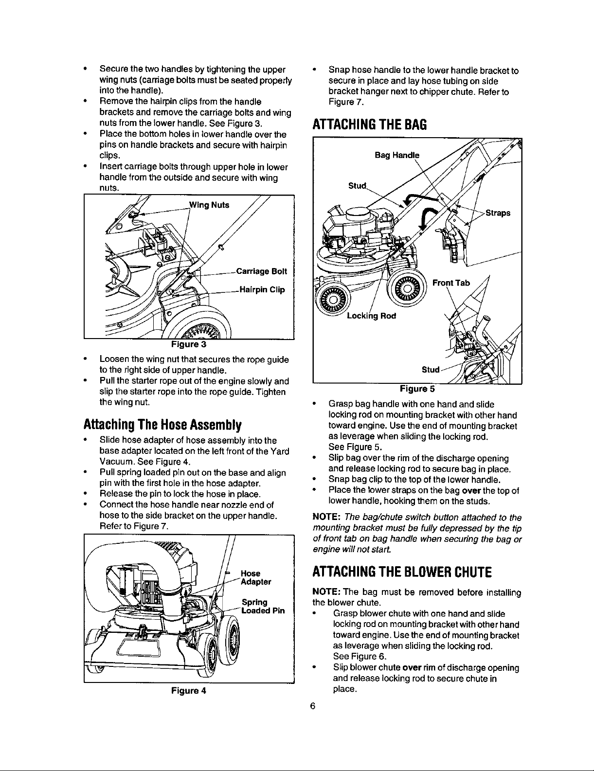
ATTACHINGTHEBAG
Figure 5
Grasp bag handle with one hand and slide
locking rod on mounting bracket with other hand
toward engine. Use the end of mounting bracket
as leverage when sliding the locking rod,
See Figure 5.
Slip bag over the rim of the discharge opening
and release locking rod to secure bag in place.
Snap bag clip to the top of the lower handle,
Place the lower straps on the bag over the top of
lower handle, hooking them on the studs.
NOTE: The bag/chute switch button attached to the
mounting bracket must be fully depressed by the tip
of front tab on bag handle when securing the bag or
engine will not start.
Figure 4
Hose
Spring
ATTACHINGTHEBLOWERCHUTE
NOTE: The bag must be removed before installing
the blower chute.
Grasp blower chute with one hand and slide
locking rod on mounting bracket with other hand
toward engine. Use the end of mounting bracket
as leverage when sliding the locking rod.
See Figure 6.
Slip blower chute over rim of discharge opening
and release locking rod to secure chute in
place.
6
Page 7

• Raise the nozzle height to the highest setting
when using the blower chute. Refer to nozzle
height adjustment in the ADJUSTMENT section.
NOTE: The bag/chute switch button attached to the
mounting bracket must be fully depressed by the tip of
front tab on the blower chute or engine will not start.
Blower
Front
Tab
Locking
Rod
king
Rod
Figure 6
7
Page 8

Know Your Yard Vacuum
Read this operator'smanualand safety rules before operatingyour Yard Vacuum. Compare the illustrations
betow with your equipment to familiarize yourself with the location of various controls and adjustments. Save
this manual for future reference.
The operation of any Yard Vacuum can result in foreign objects being thrown into the eyes,
which can result in severe eye damage. Always wear safety glasses, provided with the
Yard Vacuum, for operating this equipment or while performing any adjustments or repairs on
Starter
Bag Handle
Throttle Control
Nozzle/Hose
Vac Handle
Blower Chute
Choke Control
Nozzle Height
Adjustment Lever
OPERATINGCONTROLS(seeFigure7)
Chipper Chute
Allows twigs and small branches up to 1 1/2" in
diameter to be fed into the impeller for chipping.
Nozzle
Yard waste such as leaves and pine needles can be
vacuumed up through the nozzle for shredding.
Bag
Collects shredded material fed in through the chipper
chute or vacuumed in through the nozzle.
Blower Chute
When attached to unit, the blower chute is used to
blow or scatter yard waste such as leaves, pine
needle, or small twigs across yard.
Bag Handle
Used to grasp bag in order to assist in attaching,
removing, and emptying bag.
Spark Plug Wire \
t
Nozzle
Figure 7
Nozzle Height Adjustment Lever
Used to adjust the nozzle ground clearance ranging
from 5/8" to 4 1/8".
Throttle Control
This lever controls the engine speed and stop
function. Through three separate positions on the
lever from left to right, the operation is as follows:
Start/ Slow/ Engine
Run Idle Off
Choke Control
The choke control is used to choke of the carburetor
and assist in starting the engine.
Starter Handle
Used to start the engine.
Meets ANSI safety standards
Craftsman Yard Vacuums conform to the safety standard of the American National Standards Institute (ANSI),
8
Page 9

Hose Assembly
Used asan alternative to the nozzletovacuum yard
waste suchas leavesor pine needlesin hardto
reachplaces.
Hose Handle
Used to guidehoseassemblywhenvacuuming.
Nozzle/Hose Vac Handle
The nozzle/hose vac handle is located on top of the
nozzle and it is used to regulate the vacuum between
the nozzle and the hose assembly.
GASANDOILFILL-UP
Oil (one 20-oz. bottle shipped with unit)
Only use high quality detergent oil rated with API
service classification SF, SG, or SH. Select the oil's
SAE viscosity grade according to the expected
operating temperature. Follow the chart below.
Colder _- 32°F _ Warmer
5W_ SAE 30
Fill fuel tank with clean, fresh, unleaded regular,
unleaded premium or reformulated automotive
gasoline only. DO NOT use Ethyl or high octane
gasoline. Do not use gasoline containing
METHANOL. Replace fuel cap.
To avoid engine problems, the fuel system should
be emptied before storage for 30 days or longer.
Drain the gas tank, start the engine and let it run
until the fuel lines and carburetor are empty. Use
fresh fuel next season. See STORAGE section
for additional information.
WARNING: Use extreme care when
a,
handling gasoline. Gasoline is extremely
flammable and the vapors are explosive.
Never fuel machine indoors or while the
engine is hot or running. Extinguish
cigarettes, cigars, pipes, and other
sources of ignition.
Check the fuel level periodically to avoid running
out of gasoline while operating the Yard Vacuum.
If the unit runs out of gas as it is chipping, it may
be necessary to unclog the unit before it can be
restarted. Refer to SERVICE AND
ADJUSTMENT section.
Oil Viscosity Chart
NOTE: Although multi-viscosity oils (5W30, 10W30,
etc.) improve starting in cold weather, they will result
in increased oil consumption when used above 32°F.
Check your engine oil level more frequently to avoid
possible engine damage from running low on oil.
Remove oil fill dipstick.
With the Yard Vacuum on level ground, use a
funnel to fill engine with oil to FULL mark on
dipstick. Capacity is approximately 20 oz. Be
careful not to overfill. Overfilling will cause the
engine to smoke profusely and will result in poor
engine performance. The oil bottle packaged 1.
with your Yard Vacuum contains 20 oz. of oil.
Check the oil level making certain not to rub the 2.
dipstick along the inside walls of the oil fill tube.
This would result in a false dipstick reading. Refill
to FULL mark on dipstick, if necessary. Replace 3.
dipstick and tighten.
• Check oillevelthree times prior to starting engine
to be certain you've gotten an accurate dipstick 4.
reading. Running the engine with too little oil can
result in permanent engine damage. 5.
Gasoline
Remove fuel cap from the fuel tank.
Make sure the container from which you will pour
the gasoline is clean and free from rust or foreign
particles. Never use gasoline that may be stale
from long periods of storage in its container.
Gasoline that has been sitting for any period
longer than four weeks should be considered
stale.
TOSTOPENGINE
Move throttle control lever to STOP or OFF
position.
Disconnect spark plug wire and ground it to the
post to prevent accidental starting while the
equipment is unattended.
lever, be careful of heated surfaces and
WARNING: When moving throttle control
sharp edges on muffler guard.
TOSTARTENGINE
Attach spark plug wire and rubber boot to spark
plug.
The bag/chute switch button must be fully
depressed by the tip of front tab on bag handle
or blower chute for engine to start.
Make sure bag/chute switch wire is connected to
engine and grounded to mounting bracket.
Gas tank should be filled 3/4 to full before start-
ing.
Move throttle control to START/RUN position.
See Figure 8.
6.
Move the choke control toward the throttle
control to choke the engine's carburetor. (A
warm engine may not require choking.) See
Figure 8.
Page 10

Throttle Control
Buttons
Choke Control
Figure 8
7. Standing behind the unit, grasp starter handle
and pull rope out until you feel adrag.
8. Pull the rope with a rapid, continuous, futl arm
stroke. Keep a firm grip on the starter handle.
Let the rope rewind slowly.
9. Repeat, if necessary, until engine starts. When
engine starts, move choke control gradually
away from the throttle control.
10. If engine falters, move choke control back
toward the throttle control and repeat steps 7-9.
11. ALWAYS keep the throttle control in the START/
RUN position when operating the Yard Vacuum.
TOEMPTYBAG
• Unhook bag straps from the lower handle and
unsnap bag clip from top of the lower handle.
See Figure 9.
Grasp bag handle with one hand and pull lock rod
on mounting bracket with other hand toward
engine to release.
Remove bag from over the rim of the discharge
opening. Refer to Figure 4.
Twist the two buttons on the back of the bag to
unlock and empty contents. See Figure 9.
Hold bag handle and bag clip while emptying the
contents.
• Compress bag opening and fold inner flap over
opening.
Fold outer flap over inner flap and insed buttons
on the bag through metal outlets.
Twist the buttons to lock bag.
Inner Flap Bag
Handle
Figure 9
Clip
TOREMOVEBLOWERCHUTE
Grasp blower chute with one hand and pull lock
rod on mounting bracket with other hand toward
engine to release. Refer to Figure 6.
Remove blower chute from over the rim of the
discharge opening.
UsingtheNozzleVacuum
• Place nozzle/hose vac handle in the top position
on the nozzle to vacuum through nozzle. See
Figure 10.
The spring loaded pin must be in the first hole of
the hose adapter to operate the nozzle vac.
Place both hands on top of upper handle to push
unit over yard waste.
Yard waste such as leaves and pine needles can be
vacuumed up through the nozzle for shredding. After
material has been shredded by the flail blades on the
impeller assembly, it will be discharged into catcher
bag or through blower chute. Do not attempt to shred
or chip any material other than vegetation found in a
normal yard (i.e. branches, leaves, twigs, etc.) Avoid
fibrous plants such as tomato vines until they are
thoroughly dried out. Materials such as stalks or
heavy branches up to 1 1/2" in diameter may be fed
into the chipper chute.
WARNING: Do not attempt to shred,
A
chip, or vacuum any material larger than
specified on the machine or in this
manual. Personal injury or damage to
the machine could result.
10
Page 11

Nozzle/Hose\_
MacHandle \ --
Spring Loaded Pin
(First Hole)
Figure 10
IMPORTANT: The flail screen is located inside the
housing in the discharge area. If the flail screen
becomes clogged, remove and clean as instructed in
SECTION 5: MAINTAINING YOUR YARD VACUUM.
For best performance, it is also important to keep the
chipper blade sharp.
adjustments without first stopping engine
WARNING: Do not at any time make any
and disconnecting spark plug wire.
NozzleHeightAdjustment
The nozzle can be adjusted to any six positions,
ranging from 5/8" to 4 1/8" ground clearance. The
nozzle height has to be adjusted according to the
conditions. Move the height adjustment levers forward
or backward to adjust the nozzle upwards or
downwards. See Figure 12.
NOTE: In general, raise the nozzle height to vacuum a
thick layer of leaves or to operate with the blower chute
and lower the nozzle height for smoother surfaces.
Nozzle" Adjustment
Lever
Figure 12
UsingtheHoseAssembly
Place nozzle/hose vac handle inthe bottom
position on the nozzle to redirect vacuum to the
hose assembly. See Figure 11.
The spring loaded pin must be in the second hole of
the hose adapter to operate the hose assembly.
Unhook the hose from upper handle bracket and
grasp the hose handle to guide while vacuuming
yard waste such as leaves or pine needles in hard
to reach places.
Nozzle/Hose
Vac Handle
Spring
(Second Hole)
Figure 11
11
Page 12

MAINTENANCE a.J _ ,_#_
SCHEDULE ,_o_'=_._._ _...
I-
O Lubrication _
E3
o
Clean equipment _
Check engine oil
LU Change engine oil _ _
z
Service air cleaner
z
ug
Service spark plug _ <_//
Service muffler '_
Clean engine _ _:_
GENERALRECOMMENDATIONS
Always observe safety rules when performing any
maintenance.
• The warranty on this Yard Vacuum does not
cover items that have been subjected to operator
abuse or negligence. To receive full value from
the warranty, operator must maintain the
equipment as instructed in this manual.
Some adjustments will need to be made
periodically to maintain your equipment properly.
Follow the maintenance schedule.
• Periodically check all fasteners and make sure
they are tight.
WARNING: Always stop the engine and
&
disconnect and ground the spark plug
wire before performing any maintenance
or adjustments,
LUBRICATION
Wheels- Place a few drops of SAE 30 oil on each
shoulder screw once a season.
Refer to Figure 7.
Nozzle height adjustment levers- Lubricate
nozzle height adjustment levers with light oil.
Refer to Figure 7,
Locking Rod- Lubricate the lock rod and
compression springs which attach to the
mounting bracket. Refer to Figure 5,
CLEANEQUIPMENT
Clean the Yard Vacuum thoroughly after each
use.
Wash the bag periodically with water. Allow to
dry thoroughly in the shade.
Ifthe flail screen becomes clogged, remove and
clean as instructed in the SERVICE AND
ADJUSTMENT section.
NOTE: Cleaning with a forceful spray of water is not
recommended as it could contaminate the fuel
system.
CHECKENGINEOIL
Remove oil fill dipstick.
Check oil level on dipstick. Level should be at
FULL mark.
Replace dipstick and tighten.
CHANGEENGINEOIL
Only use high quality detergent oil rated with API
service cTassification SF, SG, or SH. Select the
oil's SAE viscosity grade according to the
expected operating temperature. Refer to
operation section for viscosity chart.
Stop engine and wait several minutes before
checking oil level. With engine on level ground,
the oil must be to FULL mark on dipstick.
Change engine oil after the first five hours of
operation, and every twenty-five hours
thereafter.
12
Page 13

TODRAINOIL
Drain oil while engine is warm. Follow the instructions
given below.
Drain the gas tank, start the engine and let it run
until the fuel line and carburetor are empty.
Remove oil fill dipstick.
• Tip unit on its side to drain through the oil fill tube.
• When engine is drained of all oil, refill with
approximately 20 oz. of fresh oil. Refer to Gas
And Oil Fill-up in OPERATION section.
Replace dipstick.
SERVICEAIRCLEANER
The air cleaner prevents damaging dirt, dust, etc.,
from entering the carburetor and being forced into the
engine and is important to engine life and
performance. The air cleaner consists of a foam filter.
Never run the engine without an air cleaner
completely assembled.
TOService Air Cleaner:
Remove foam filter from plastic housing on top of
engine.
Wash in water and detergent solution, and
squeeze (do not twist) until all dirt is removed.
Rinse thoroughly in clear water.
Wrap in a clean cloth and squeeze (do not twist)
until completely dry, or allow to air dry.
Saturate with engine oil and squeeze to distribute
oil and remove excess oil.
Replace foam filter in plastic housing
NOTE: ff the foam filter is tom or damaged in any
way, replace it.
_lb ARNING: WARNING: Temperature ofmuffler end nearby areas may exceed
150 ° F(65°C). Avoid these areas.
SERVICESPARKPLUG
Clean the spark plug and reset the gap to .030" at
least once a season or every 50 hours of
operation. See Figure 13. Spark plug
replacement is recommended at the start of each
season. Refer to engine parts list for correct
spark plug type.
NOTE: Do not sandblast spark plug. Spark plug
should be cleaned by scraping or wire brushing and
washing with a commercial solvent.
Figure 13
SERVICEMUFFLER
Inspect muffler periodically, and replace if
necessary.
If your engine is equipped with a spark arrester
screen assembly, remove after every 50 hours of
use for cleaning and inspection. Replace if
damaged.
WARNING: Do not operate the Yard
&
Vacuum without a muffler or tamper with
the exhaust system. Damaged mufflers
or spark arresters could create a fire
hazard.
CLEANENGINE
Clean engine by removing dirt and debris with a
cloth or brush.
Frequently remove grass clippings, dirt, and
debris from cooling fins, air intake screen, levers,
and linkage. This will help ensure adequate
cooling and engine speed.
13
Page 14

adjustment to the unit without first
WARNING: Do not at any time make any /_,
stopping engine and disconnecting
spark plug wire.
NozzleHeightAdjustment
The nozzle can be adjusted to any six positions,
ranging from 5/8" to 4 1/8" ground clearance. The
nozzle height has to be adjusted according to the
conditions. Move the height adjustment levers
forward or backward to adjust the nozzle upwards or
downwards. See Figure 14.
NOTE: In general, raise the nozzle height to vacuum
a thick layer of leaves or to operate with the blower
chute and lower the nozzle height for smoother
surfaces.
WARNING: Do not attempt to alter the
engine speed by tampering with the
engine's governor linkage. Doing so
could result in serious personal injury
and damage to the engine. The engine
RPM has been set at the factory.
REMOVINGTHEFLAILSCREEN
If the discharge area becomes clogged, remove the
flail screen and clean areaas follows.
Stop the engine. Make certain the chipper
shredder vacuum has come to a complete stop.
Disconnect and ground the spark plug wire
before unclogging the discharge chute.
Remove the vacuum bag or blower chute from
the unit as instructed in the OPERATION section
to obtain access to flail screen. See Figure 15.
tex Screw & Flat Washer /,
f
ght
Nozzle
Adjustment
Lever
Figure 14
CARBURETORADJUSTMENT
WARNING: If any adjustments (e.g.
carburetor) are made to the engine
while the engine is running, keep clear
of all moving parts. Be careful of heated
surfaces and muffler.
The carburetor has been pre-set at the factory and
should not require adjustment. If your engine does
not operate properly due to suspected carburetor
problems, take your Yard Vacuum to a Sears Service
Center for repair and adjustment.
ENGINESPEED
The engine speed on your Yard Vacuum has been
set at the factory. Do not attempt to increase the
engine RPM. Ifyou think that the engine is running
too fast or too slow, take your Yard Vacuum to the
nearest Sears Service Center for repair and adjust-
ment.
REAR VIEW
Figure 15
Remove hex screw on right side of unit that
attaches to the flail screen. See Figure 16.
Hex Screw
Figure 16
• Remove hex screw and flat washer on top of rear
housing near mounting bracket and the lock nut
that secures flail screen. See Figure 15.
• Remove and clean the screen by scraping or
washing with water. Reinstall the screen.
14
Page 15

SHARPENINGORREPLACINGCHIPPER
BLADE
Because the engine on this unit has a tapered
crankshaft, a special impeller removal tool (part
number 753-0900) is required to remove the impeller
assembly. For further assistance, contact your Sears
Service Center.
NOTE: When tipping the unit, empty the fuel tank and
keep engine spark plug side up.
Disconnect and ground the spark plug wire.
Remove the front hubcaps, lock nuts, front
wheels, and wave washers that attach to the pivot
arm assemblies. See Figure 17,
Remove the shoulder screws and bell washers
that go through the pivot arms and height bracket
adjusters to the front support brace.
Remove lock nut that secures flail screen to the
lower housing. The flail screen does not have to
be removed. Refer to Figure 15.
Remove the hex bolt, lock washer, and flat
washer that secure the impeller assembly to the
crankshaft. See Figure 19.
Upper
Dhippm
Blade
._._ Housing
Impeller
JAssembly
ex Bolt
"Lock Washer
Fiat Washer
Pivot Arm Assembly
Bell Washer
Wave Washer
Bracket
Screw Lock
Figure 17
Remove the three screws on the upper housing
that secure the nozzle cover and the nine screws
that secure the lower housing to the upper
housing. See Figure 18.
Housing
o 0
BOTTOM VIEW
Figure 19
Apply lubricant to the threads of impeller removal
tool and then thread the tool into the crankshaft.
Stop when the impeller assembly can move on
the crankshaft.
Remove the impeller assembly from the
crankshaft. Unthread the impeller removal tool
from the impeller assembly.
Remove the chipper blade using a 3/16" allen
wrench on the outside of the blade and 1/2"
wrench on the underside of impeller assembly.
Replace or sharpen chipper blade.
When sharpening blade, protect hands by using
gloves and follow the original angle of grind.
Reassemble by performing the previous steps in
reverse order.
• Tighten blade screws to 210 - 250 in-lbs.
• Tighten impeller bolt to 375 - 425 in-lbs.
NOTE: Make certain chipper blade is reassembled
with the sharp edge facing upward. See Figure 20.
• Chipper
_Flall
Blade
Screws
Figure 18
Lower Housing
Screws
_lmpeller
_r _L_/ Assembly
Figure 20
15
Page 16

PrepareyourCraftsmanYardVacuumforstorageat
theendoftheseasonoriftheunitwillnotbeusedfor
30daysorlonger.Ayearlycheck-upbyyourlocal
SearsServiceCenterisagoodwaytoensurethatthe
unitrunsproperlynext season.
YardVacuum
Clean the equipment thoroughly.
Wipe equipment with an oiled rag to prevent rust.
Use a light oil or silicone to wipe.
Service the engine following instructions below.
Store unit in a clean, dry area. Do not store next to
corrosive materials such as fertilizer.
Engine
IMPORTANT: It is important to prevent gum deposits
from forming in essential fuel system parts such as
the carburetor, fuel filter, fuel hose, or tank during
storage. Also, alcohol blended fuels (called gasohol or
using ethanol or methanol) can attract moisture which
leads to separation and formation of acids during
storage. Acidic gas can damage the fuel system of an
engine while in storage.
To avoid engine problems, the fuel system should be
emptied before storage of 30 days or longer. Follow
these instruction:
Drain the fuel tank.
Start the engine and let it run until the fuel lines
and carburetor are empty.
Drain carburetor.
Never use engine or carburetor cleaner products
in the fuel tank or permanent damage may occur.
NOTE: Fuel stabilizer is an acceptable altemative in
minimizing the formation of fuel gum deposits during
storage.
Add stabilizer to gasoline in fuel tank or storage
container.
• Always follow the mix ratio found on stabilizer
container.
• Run engine at least 10 minutes after adding
stabilizer to allow the stabilizer to reach the
carburetor.
• Do not drain the gas tank and carburetor if using
fuel stabilizer. Drain all the oil from the
crankcase (this should be done after the engine
has been operated and is still warm) and refill the
crankcase with fresh oil.
If you have d rained the fuel tank, protect the inside of
the engine as follows:
Remove spark plug, pour approximately 1/2
ounce (approximately one tablespoon) of engine
oil into cylinder and crank slowly to distribute oil.
Replace spark plug.
Other
Do not store gasoline from one season to
another.
Replace the gasoline can if it starts to rust. Rust
and/or dirt in the gasoline will cause problems.
Store unit in a clean, dry area. Do not store next
to corrosive materials, such as fertilizer.
NOTE: If storing in an unventilated or metal storage
shed, be certain to rustproof the equipment by coat-
ing with a light oil or silicone.
16
Page 17

Problem Possible Cause(s) Corrective Action
Enginefailstostart 1. Fueltankemptyorstalefuel. 1.
Filltank with clean, fresh gasoline. Fuel will not
last over thirty days unless a fuel stabilizer is
added.
2. Spark plugwire disconnected.
3. Cannot pull recoilcord.
2. Connect wire to spark plug.
3. Obstruction lodged in impeller. Disconnect
spark plug wire and remove lodged object.
4. Choke not in ON position.
5. Faulty spark plug.
6. Safety switch not depressed.
4. Move CHOKE to ON position.
5. Clean, adjust gap or replace.
6. Safety switch must be depressed bythe front
tab on the bag handle when securing the bag.
7. Safety switch wire is not
connected to engine or not
properly grounded.
Lossofpower;
operation erratic
Too much vibration
Engine overheats 1. Carburetor not adjusted 1.
Unit does not 1. Discharge chute clogged. 1.
discharge
Rate of discharge
slows considerably or
1. Spark plug wire loose.
2. Unit running on CHOKE.
3. Blocked fuel line or stale fuel.
4. Water or dirt in fuel system.
5. Carburetor out of adjustment.
6. Lowengine RPM.
1. Loose parts or damaged
impeller.
2. Engine oil level low 2.
2. Foreign object lodged in
impeller.
3. Lowengine RPM.
4. Vacuum bag is full.
1. Lowengine RPM.
2. Chipper blade dull.
composition of
7. Connect safety switch wire to engineconnector
and ground to mounting bracket.
1. Connect and tighten spark plug wire.
2. Move choke lever to OFF position.
3. Clean fuel line; fill tank with clean fresh
gasoline. Fuel will not last over thirty days
unless a fuel stabilizer is used.
4. Disconnect fuel line at carburetor to drain fuel
tank. Refill with fresh fuel.
5. Contact your Sears Service Center.
6. Always run engine at full throttle.
1. Stop engine immediately and disconnect spark
plug wire. Have unit serviced by a Sears
Service Center.
Contact your Sears Service Center.
Fill crankcase with proper selection of oil.
Stop engine immediately and disconnect spark
plug wire. Clean flail screen and inside of
discharge opening. Bee Maintenance section of
this manual.
2.
Stop engine immediately and disconnect spark
plug wire. Remove lodged object.
3.
Always run engine at full throttle.
4.
Empty bag.
1.
Always run engine at full throttle.
2.
Replace chipper blade or see your Sears
Service Center.
discharged material
changes
NOTE: For repairs beyond the minor adjustments listed above, please contact your local Sears Service Center.
17
Page 18

Sears Craftsman 6.0 H.P. Yard Vacuum Model 247.770550
-11
7
17
/
15
48
47
33 34 35
51
4O
19
18
Page 19

Sears Craftsman 6.0 H.P. Yard Vacuum Model 247.770550
Ref.
No.
2. 749-1423
3. 720-0279
4, 712-3004A
5. 710-1205
6. 781-1056
7. 710-0528
8. 720-0314
9. 710-1174
11. 710-0604A
12. 681-0174
13. 749-0907B
14. 711-1293
15. 710-0703
16. 712-0397
17, 751B282454
18. 725-1700
19. 725-3166
20. 731-1613
21. 710-0224
22. 629-0920
23. 714-0104
24. 736-0264
25. 732-0962
26. 781-0778A
27, 747-1153
28. 710-3195
29. 710-3025
Part No.
Part Description No.
Ref.
Upper Handle 30,
Knob 31.
Flange Lock Nut 5/16-18 32.
Eye Bolt 33,
Upper Handle Bracket 34.
Hex Cap Screw 5/16-18 x 1.25 35.
Handle Knob 5/16-18 36,
Carriage Bolt 37.
Hex Washer Screw 5/16-18 x,625 38.
Lower Handle Bracket 39.
Lower Handle 40,
Studs 41.
Carriage Screw 1/4-20 x.75 42.
Wing Nut 1/4-20 43.
Shroud 44.
Switch Cover 45.
Safety Switch 46.
Safety Switch Cover 47.
Hex Washer Screw #10-16 x.50 48.
Wire Harness 49.
Cotter Pin 50.
Flat Washer.330 ID x.630 OD 51.
Compression Spring 52.
Mounting Bracket 53.
Lock Rod 54.
Hex Cap Screw 5/16-18 x 4.5 55.
Hex Cap Screw 5/16-18 x.625 56.
Part No.
710.0502A
710-0751
;731-2484
716-0104
732-3035
711-1571
736-3020
710-0969
710-0425
781-1042
726-0454
710-3008
681-0122
738-1167
736-0371
781-1058
712-3027
748-0457
731-2478
710-3288
723-0295
749-1270
764-0648
07071
731-2292
736-0607
712-9161
Part Description
Hex Washer Screw 8/8-16 x t.25
Hex Cap Screw 1/4-20 x .620
Hose Base Adapter
E Ring .500 Dia
Compression Spring
Clevis Pin
Flat Washer _271 ID x .630 OD
Screw #12-16 x 1.0
Machine Screw #10 - 24 x ,625
Upper Housing
U-Clip Lock Nut 5/16-18
Hex Cap Screw 5/16-18 x.75
Chipper Chute Assembly
Stud 5/16-18 x .56
Flat Washer .343 ID x .860 OD
Hose Bracket Hanger
Hex Flange Nut 1/4-20
Spacer
Hose Nozzle
Hex Cap Screw 1/4-20 x 2.625
Adjustment Clamp
Nozzle Handle
Vacuum Hose
Handle Grip
Hose Adapter
External L-Washer 5/16
Hex Lock Nut #10 -24
NOTE: For painted parts, please refer to the list of color codes below. Please add the applicable color code, wherever needed,
to the part number to order a replacement part. For instance, if a part, numbered 700-xxxx, is painted polo green, the part num-
ber to order would be 700-xxxx-0689.
Polo Green: 0689
Oyster Grey: 0662
Powder Black: 0637
19
Page 20

Sears Craftsman 6.0 H.P. Yard Vacuum Model 247.770550
41 39
23
/
19
15
36
32_
45
46
49
53
44
51
54
20
Page 21

Sears Craftsman 6.0 H.P. Yard Vacuum Model 247.770550
Ref.
No,
1. 664-0094
2, 661-0154
3. 710-1054
4. 731-0490
5. 681-0152
6. 781-0735
7. 719-0329
8. 715-0166
9. 711-1401
10. 736-0247
11. 736-0217
12. 710-0818
13, 710-3038
14. 781-0721A
15. 712-3004A
16. 712-3027
17. 736-0142
18. 714-0225
19, 711-1560
20. 731-2294
21. 781-1064
22. 732-1156
23. 726-0106
24. 711-1551
25, 712-0161
26. 736-0400
27. 731-2485
28. 710-1156
29. 750-1294
30. 732-3118
31. 732-1151
Part No.
Part Description No. Part No.
Ref.
Bag Assembly 32, 732-1150
Screen Assembly 33. 731-2294
Hex Screw 5/16-24 x 1.0 34. 711-1582
Chipper Blade 35. 781-0725A
Impeller Assembly 36. 781-0777
Pin Clip 37. 681-0155
Flail Blade 661-0156
Spiral Pin 38. 714-0104
Clevis Pin 39. 710-3925
Flat Washer,375 ID x 1.25 OD 40. 736-0195
Lock Washer 3/8 41. 734-1992
Hex Cap Screw 3/8-24 x 2.0 42. 736-0232
Hex Cap Screw 5/16-18 x .875 43. 738-1015
Lower Housing 44, 731-0981A
Flange Lock Nut 5/16-18 45. 781-0785
Hex Flange Nut 1/4-20 46. 738-1185
Flat Washer .261 ID x .50 OD 47. 741-0751
Cotter Pin 48. 682-0113
Pivot Rod 49. 729-0426
Nozzle 50, 732-1026
Base Adapter Door 51, 736-0741
Torsion Spring 62. 738-1173
Cap Speed Nut 1/4 53. 734-1978
Pivot Rod 54. 712-0431
Hex Lock Nut #10-24 55. 726-0453
Flat Washer .194 ID x .62 OD 56. 712-0158
Nozzle Door Lever 57. 736-0314
Hex Screw #10-24 x 1,25 58. OEM-290-012
Shoulder Spacer 59. 764-0631
Extension Spring 60. 631-0383
Torsion Spring LH
Part Description
Torsion Spring RH
Nozzle Door
Rod .25 x 1.25 Lg
FrontWheel Support Brace
Rear Wheel Support Brace
Handle Bracket Ass"y LH
Handle Brkt Ass"y RH (Not Shown)
Cotter Pin
Hex Cap Screw 5/16-18 x,625
Bell Washer.401 ID x.870 OD
Wheel 9 x 2
Wave Washer .531 ID x ,781 OD
Shoulder Screw 3/8-16
Hubcap
Height Adjustment Bracket
Stud 5/16-18.56 x .75
Height Adjustment Bearing
Pivot Arm Assembly
Height Adjustment Knob
Spring Lever
Bell Washer .760 ID x .25 OD
Shoulder Screw .750 ID x .625 OD
Wheel 8 x 2
Flange Lock Nut 3/8-16
Lock Nut3/8-16
Hex Lock Nut 5/16-18
Thrust Washer .375 ID x .70 OD
Blower Chute (If Equipped)
Bag
Chute Assembly
NOTE: For painted parts, please refer to the list of color codes below. Please add the applicable color code, wherever needed,
to the part number to order a replacement part. For instance, if a part, numbered 700-xxxx, is painted polo green, the part num-
ber to order would be 700-xxxx-0689.
Polo Green: 0689
Oyster Grey: 0662
Powder Back: 0637
21
 Loading...