

Page 1
r
OWNER’S MANUAL
FIFTY CENTS
ASSEMBLY
OPERATION
MAINTENANCE
PARTS LIST
Important:
Read Safety Rules and
Instructions Carefully
Model No.
249-640A
PRINTED IN U.S.A.
FORM No. 770^8251
Page 2

♦♦♦♦♦♦♦♦♦♦♦♦♦♦♦♦♦♦♦♦♦♦♦♦♦♦♦♦♦♦♦♦♦♦♦♦♦♦♦♦♦♦♦♦♦♦♦♦♦♦♦♦♦♦♦♦♦♦♦♦♦♦♦
♦ ♦
♦ ♦
UMITED WARRANTY
♦
♦
♦
♦
♦
For one year from the date of original retail purchase, MTD PRODUCTS INC will either
repair of replace, at its option, free of charge, F.O.B. factory or authorized service firm,
any part or parts found to be defective in material or workmanship. Transportation charges
under this warranty must be paid by the purchaser unless return is requested by
MTD PRODUCTS INC.
♦
♦
♦
♦
♦
♦
♦
♦
♦
♦
♦
♦
♦
♦
This warranty will not apply to any part which has becomes inoperative due to misuse,
excessive use, accident, neglect, improper maintenance, alterations, or unless the unit
has been operated and maintained in accordance with the instructions furnished. This
warranty does not apply to the engine, motor, battery, battery charger or component parts
thereof. Please refer to the applicable manufacturer's warranty on these items.
This warranty will not apply where the unit has been used commercially.
Warranty service is available through your local authorized service dealer or distributor. If
you do not know the dealer or distributor in your area, please write to the Customer Service
Department of MTD.
This warrarity gives you specific legal rights. You may also have other rights which vary
from state to state.
WARNING TO PURCHASERS
OF INTERNAL COMBUSTION ENGINE EQUIPPED
MACHINERY OR DEVICES IN THE STATE OF CALIFORNIA
The equipment which you have just purchased does not have a spark arrester. If this equipment is used on
any forest covered land, brush covered land, or grass covered unimproved land in the State of California,
before using on such land, the California law requires that a spark arrester be provided. In addition, spark
arrester is required by law to be in effective working order. The spark arrester must be attached to the
exhaust system and comply with Section 442 of the California Public Resources Code.
Page 3
IMPORTANT
It is suggested that this manual be read in its entirety before attempting to assemble or operate. Keep
this manual in a safe place for future reference and for ordering replacement parts.
This unit is shipped WITHOUT GASOLINE or OIL. After assembly, see operating section of this manual
for proper fuel and amount.
Your log splitter is a precision piece of power equipment, not a plaything. Therefore exercise extreme
caution at all times.
SAFE OPERATION PRACTICES FOR LOG SPLITTERS
TRAINING
1. Know the controls and how to stop quicklyREAD THE OWNER'S MANUAL.
2. Do not allow children to operate. Do not allow
adults to operate it without proper instruction.
Only persons well acquainted with these rules of
safe operation should be allowed to use your log
splitter.
PREPARATION
1. Do not wear loose fitting clothing that could get
caught on the moving parts.
Do not operate equipment when barefoot or wear
ing open Sandies. Always wear substantial foot
wear.
3. Check the fuie before starting the engine. Do not
fill the gasoline tank indoors, when the engine is
running, or while the engine is still hot. Wipe off
any spilled gasoline before starting the engine.
4. Use only in daylight or in good artifical light.
5. Never operate the equipment in the rain. Always
be sure of your footing.
OPERATION
C. Open doors if engine is run in garage-
exhaust fumes are dangerous. Do not run
engine indoors.
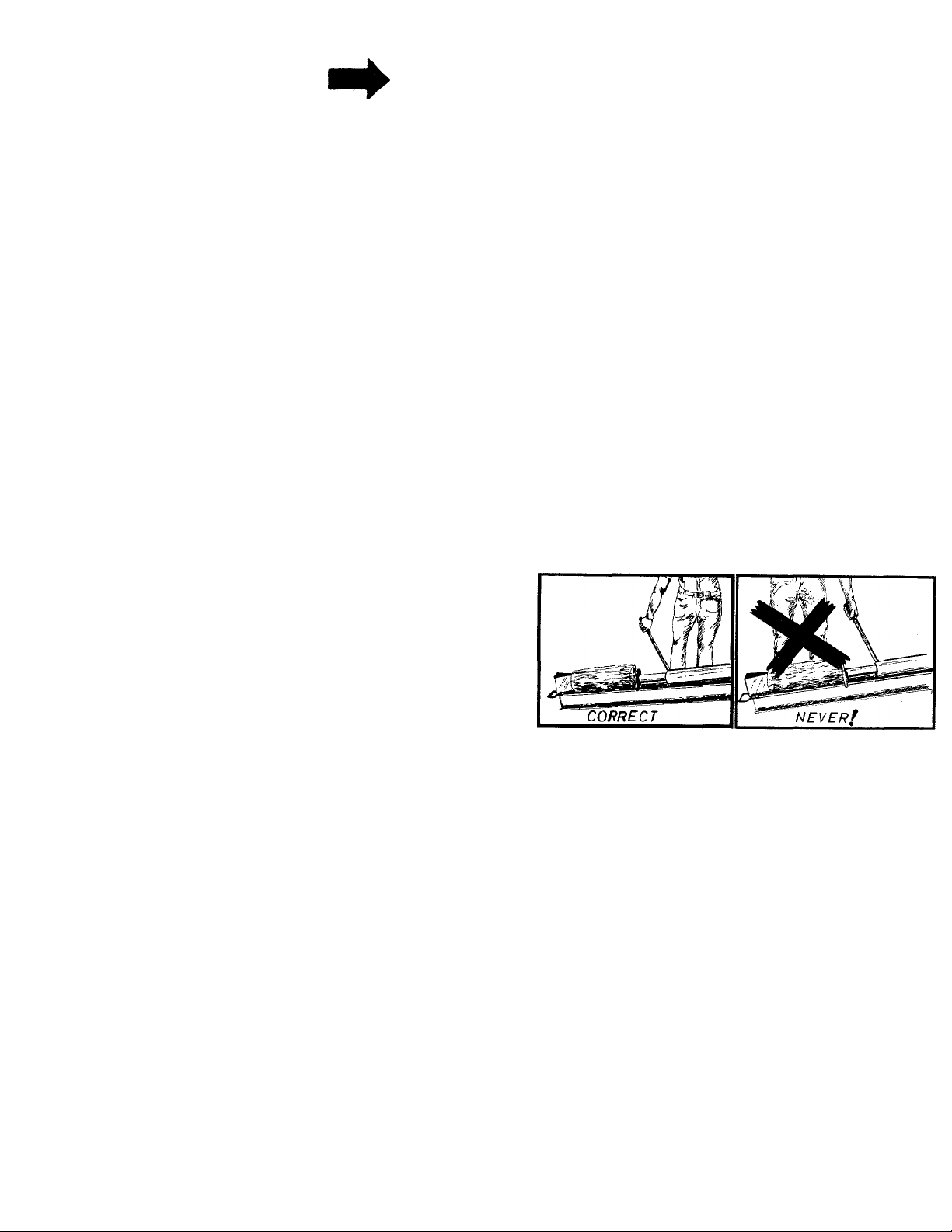
6. Always operate the log splitter from the engine
side of the beam.
Stand behind the ram when operating. See drawings.
7. Be careful not to touch the muffler after the
engine has been running, it is HOT.
1. Do not change the engine governor settings or
overspeed the engine. Excessive engine speeds are
dangerous.
2. Do not put hands or feet near rotating or moving
parts.
3. If the equipment should start to vibrate abnor
mally, stop the engine and check immediately for
the cause. Vibration is generally a warning of
trouble.
4. When cleaning, repairing or inspecting, make
certain all moving parts have stopped. Disconnect
the spark plug wire, and keep the wire away from
-V, the plug to prevent accidental starting.
Handle gasoline with care-it is highly flammable.
A. Use approved gasoline container.
B. Never remove cap or add gasoline to a running
or hot engine or fill guel tank indoors. Wipe
up spilled gasoline.
MAINTENANCE and STORAGE
1. Keep all nuts, bolts, screws, hose clamps and
hydraulic fittings tight to be sure equipment is
in safe working condition.
2. Never store the equipment with gasoline in the
tank inside of a building where fumes may reach
an open flame of spark. Allow the engine to cool
before storing in any enclosure.
3. To reduce fire hazard keep engine free of grass,
leaves, wood chips, excessive grease and oil.
4. Do not change the engine governor settings or
overspeed the engine. Excessive engine speeds
are dangerous.
5. Never store outside without a waterproof cover.
Rain will cause rust on the inside of the cylinder.
Page 4

TOOLS REQUIRED:
(1) 1-1/8" wrench or adjustable wrench
(2) 1/2" wrenches
(1) 3/4" wrench
(2) 7/16" wrenches
(2) 9/16" wrenches
OTHER MATERIALS NEEDED:
(A) One gallon or regular grade gasoline (for engine)
(B) 2-3/4 pints of SAE 30 or 10W oil (for engine)
(C) 2-1/2 gallons of 10W 30 H.D. oil only (for
Splitter)
(D) Cleaning rag
(E) Funnel
(F) Hydraulic sealant tape (for pipe threads)
-r K—
C-' * F.
G-
H-
Your Log Splitter is shipped in two cartons.
1. Remove the engine (with frame), two wheels
engagement rod, engagement handle, hoses and
hardware pack. See figures 1 & 2.
2. Remove the beam assembly from the other carton.
L
---
iTTT
figure 1
i
LIST OF CONTENTS IN HARDWARE PACK:
See figure 1.
A. (2)
B.
C. (2)
D.
E.
F.
G. (4)
H. (4)
1. (4)
J.
K.
L.
M.
N.
0.
P.
Q.
R.
Sq. Head Set Screws
Collars
(2)
Spacers
Hex Nut 3/8-24 Thread
(1)
Pivot Bushing
(1)
Hair Pin Cotter
(1)
Hex Screws 5/16-24 x 1.00" long
Lockwashers 5/16" Scr.
Hex Nuts 5/16-24 Thread
Shoulder Bolt
(1)
Hex Nut 3/8-16 Thread
(1)
Stud 3/8-16 X 2.75" Long
(1)
Hose Clamp
(1)
Shoulder Bolt
(1)
Flat Washer
(1)
Forward Stroke Stop Bracket
(1)
Hex Screw 1/4-20 x 1.25" Long
(1)
Hex Nut 1/4-20 Thread
(1)
.ENGAGEMENT ROD
ENGAGEIVi NT HANDLE
,V FORWARD
STROKE
HIGH
PRESSURE
HOSE
HIGH
PRESSURE
HOSE
FIGURE 2
Page 5

ASSEMBLY INSTRUCTIONS
1. Block up rear end of log splitter so that the rear
wheels may be assembled.
2. Place spacers (C) on axle, then wheels and secure
with collars (B) and set screws (A). See figure
3.
5. Place end of stud through the middle hole of
engagement handle and then tighten hex nut (K).
See figure 4.
6. Secure stop bracket (P) to beam with shoulder
bolt (J). See figure 5.
FIGURE 3
3. Place stop bracket (P) through slot in beam. Place
engagement handle through slot in beam. See
figure 4.
4. Place stud (L) through stop bracket (P) and start
hex nut (K) on by hand. See figure 4.
ENGAGEME
HANDL
FIGURE 5
7. Secure engagement handle to beam with shoulder
bolt (N) and flat washer (0). See figure 6.
FIGURE 4 FIGURE 6
Page 6

8. Place end of engagement rod on valve spool and
secure with hex screw (Q) and hex nut (R).
See figure 7.
NOTE
Engagement handle locked in reverse
position must depress valve spool to
limit.
10. Secure pivot bushing in place on engagement
rod with hex nut (D).
11. Secure the inlet hose to the pump with hose
clamp (M), provided in hardware pack. A standard
screw driver is required. See figure 9.
FIGURE?
9. Thread pivot bushing (E) on end of engagement
rod so there is approximately 1/2" of thread
showing. Engagement handle must beat 90° to
beam. Insert pivot bushing (E) into engagement
handle. See figure 8.
PIVOT 13USHIIMG (E)
HEX NUT ID)
- 'f..
. 'hair pin
^COTTER (F)
FIGURE 9
12. Assemble the forward stroke high pressure hose to
the valve. An adjustable wrench is required.
See figure 10.
FORWARD
STROKE
HIGH PRESSURE
HOSE
ADJUSTABL WRENCH
i
-
FIGURES
FIGURE 10
Page 7

NOTE
Use hydraulic sealant tape or pipe
sealant on threads.
13. Assemble the other end of forward stroke high
pressure hose to 90° pipe adapter. (Located at
rear of cylinder). See figure 11. An adjustable
wrench is required.
WARD STROKE
HOSE
90°
PIPE
ADAPTER
15. Assemble other end of high pressure hose to
valve. See figure 13. An adjustable wrench is
required.
FIGURE 11
14. Assemble high pressure hose to pump. See figure
12. An adjustable wrench is required.
FIGURE 13
OPERATION
1. Service engine with gas and oil. See'engine manual
packed with log splitter for complete instructions
for the care and maintenance of engine. READ
DIRECTIONS CAREFULLY.
CAUTION
A
You must not operate log splitter
without proper amount of oil in
reservoir tank.
FIGURE 12
Remove the breather plug from breather tube. See
figure 14. Pour 2-1/2 gallons of 10W30 H.D. oil
7 ON LY into breather tube.
Page 8

LOG SPLITTER:
The oil in the reservoir should be changed every (100)
hours of operation.
Check oil in log splitter reservoir before every use;
See figure 16.
1. Block up front of log splitter so beam is setting
level.
2. Remove check pipe plug in rear of beam. See
figure 16. If oil starts to come out of check
pipe plug hole, oil level is correct. IF NOT add
oil to breather tube (figure 14) until oil starts out.
NOTE
Use hydraulic sealant tape or pipe
sealant on pipe plug threads.
FIGURE 14
3. Open the breather valve. Valve must be open when
running log splitter. Valve must be closed when
transporting log splitter. See figure 15.
VALVE IN OPEN POSITION
VALVE IN CLOSED
POSITION
3. Replace check pipe plug, remove block frorp
under front of beam.
BREATHER PLUG AND VALVE.
NOTE: Valve has left hand threads.
Clockwise to close.
FIGURE 15
FIGURE 16
Page 9

BEFORE STARTING
During initial break-in period, oil level should be
=»»»—closely. See ENGINE MAINTENANCE.
TO START ENGINE
1. Place control lever (on engine) in run position.
See figure 18.
Jse MS classification oil. Do not use oils marked
only MM or ML or unmarked.
Above 32° use ASE 30; below 32° use SAE lOW.
These recommendations must be followed for best
performance and long life.
Change oil first two (2) hours of operation and
check oil level every five (5) operating hours or
each time equipment is used.
Change oil every twenty-five (25) operating hours
or sooner if equipment is operated in extremely
dusty or dirty conditions. See figure 17.
NOTE
Carburetors are preset at the factory.
DO NOT attempt to make adjustments
at this time. See carburetor
instructions outlined under CAR
BURETOR ADJUSTMENT.
2. Move choke lever to CHOKE position. See
figure 19.
3. Rewind starter—use quick full arm stroke. Keep
firm grip on handle and return rope slowly.
TO STOP ENGINE
1. Move control lever to STOP position. See figure
18.
2. Remove high tension wire from spark plug to
prevent accidental starting by children while
equipment is unattended.
FIGURE 17
FIGURE 19
Page 10

USING YOUR LOG SPLITTER
Your log splitter is designed for safe, efficient,
operation. CARE, OF COURSE, MUST BE EXER
CISED THAT HANDS ARE KEPT AWAY FROM
MOVING PARTS.
A. Set throttle at maximum speed.
B. Engagement handle has three positions: Forward-
moves ram toward wedge. Neutral—ram stops in
place. Reverse—ram returns. See figure 20.
E. Slowly move engagement handle forward until
ram rests against log. Release engagement handle
(Neutral).
F. Remove your hand from the log and step behind
the ram. See figure 22.
FIGURE 22
G. Move engagement handle forward until log is
split.
FIGURE 20
C. Maximum length that can be split is 23".
D. Place log on beam and hold in place with right
hand. See figure 21.
NOTE
If you attempt to run the ram beyond
its normal stroke it will automatically
return the engagement handle to
neutral.
H. Move the engagement handle to the rear to return
ram.
DANGER
Never attempt to cut a log in half
with the log splitter. See figure 23.
Never stand next to the ram when
operating. See figure 24. Always stand
behind the ram.
FIGURE 21
10
FIGURE 23
Page 11

NOTE
When the pressure relief valve opens
a loud high pitched sound is heard
and engine labors.
HOSE CLAMPS
Check the hose clamps on the bottom of the pump
for proper tightness before each use.
Hose clamps on the return hose should be checked
once a season.
STRAINER TUBE ASSEMBLY
FIGURE 24
The ram should take approximately
30 seconds to make a complete cycle.
This speed may vary depending on
throttle setting and temperature of oil.
MAINTENANCE
\ WARNING \
NOTE
If the ram does not move back and forth smoothly
the strainer tube assembly may be clogged.
To clean follow these steps.
1. Remove the hose clamp at inlet hose (bottom
hose on rear of beam).
NOTE
Be prepaired to catch oil in some
container.
2. Pull off inlet hose from strainer tube assembly
and catch oil in a suitable container. See figure 25.
3. With an adjustable wrench remove the strainer
tube assembly. See figure 25.
Always stop engine and disconnect
spark plug wire before doing any
maintenance.
RAM OPERATION
^y«'****‘‘^ the ram does not move smoothly, run the ram its
jII stroke several times to clear out air in the system.
Be sure the breather valve is open.
If this does not correct the problem see strainer tube
assembly paragraph. 11
Page 12

NOTE
ENGINE MAINTENANCE
The strainer tube assembly is 53" long.
4. Clean and reassemble using- a hydraulic pipe
sealant on the threads.
PRESSURE RELIEF VALVE SETTING
If the pressure relief valve is set too low it will open up
before enough pressure is built up to properly operate
the ram. See figure 26.
TO SET THE PRESSURE RELIEF VALVE
1. Have someone place a log crossways in the Splitter
and allow the Ram to push against it with the
engine running wide open.
2. If the engine beings to lug down, the Relief Valve
setting is correct.
3. If adjustment is necessary, tighten the screw until
the engine begins to lug down.
To obtain long life and trouble-free service from yoiiir
engine, certain normal maintenance must b^
performed as outlined below:
1. Change oil in crankcase after first two (2) hours
of operation. Then, follow instructions outlined
on page 9.
SOCKET HEAD
SCREW
FIGURE 26
FIGURE 27
A
Disconnect high tension wire at spark
plug to prevent accidental starting
of engine. Unscrew oil drain plug
located on side at bottom of engine
See figure 27.
Always tip engine towards oil drain
hole. Be sure oil drains completely.
Replace oil drain plug and refill with oil as direct
on page 5 or engine nameplate.
2. Check oil every five (5) operating hours or each
12
time equipment is used.
CAUTION
NOTE
1
Page 13

3. Cleaning engine—This is an aircooled engine which
operates most efficiently when the cooling fins
are clean.
,si»—^ean cylinder fins and underside of tank or housing
oroughly of all accumulated grass and debris.
4. Air Cleaner. (See figure 28).
Paper Type Element. Remove every 10 hours or
a.
oftener if under dusty conditions. Tap to remove
loose dirt and/or blow from inside out with low
pressure air. Replace if torn or perforated or
when plugged to maintain proper carburetor
setting (50 hours). DO NOT WASH IN ANY
LIQUID AND DO NOTOIL.
Paper Element
7. Hold throttle lever closed or move carburetor
control to IDLE or SLOW position and adjust
idle adjusting needle until engine runs smoothly
proceeding in step six (6) above.
8. Allow several seconds between each adjustment
when performing either step six (6) or seven (7)
to allow engine to react to new setting.
Element
Attaching Screw
FIGURE 28
CARBURETOR ADJUSTMENTS (See figure 29)
Do not make unnecessary adjustment. Factory
settings are correct for most application. If
adjustments are needed, proceed as follows:
1. Close power adjusting needle (figure 29) by
turning to right (clockwise). Close finger tight
only. Forcing will cause damage.
2. Open one turn (counterclockwise).
3. Close idle adjusting needle (figure 29) by turning
to right (clockwise). Close finger tight only.
Forcing will cause damage.
4. Open one and one-half (1-1/2) turns (counter
clockwise).
5. Start engine. Follow starting instructions page 5.
With throttle open (carburetory control at RUN
or FAST position) adjust power adjusting needle
one-eighth (1/8) turn at a time forward to back
ward until engine runs smoothly. If engine tends
to stall under lead enrich mixture slightly
(counterclockwise).
POWER ADJUSTING
NEEDLE
FIGURE 29
STORAGE INSTRUCTIONS
In event engine is to be stored for any length of
time (30 days or more), prepare as follows:
1. Drain gasoline by tipping or by syphon hose,
then run engine until remainder is used and tank
and carburetor are empty.
CAUTION
A
Drain into container outdoors away
from fire or flame.
2. Drain carburetor by running engine until it stops
3. Inside protecting of engine for storage is per
formed by removing spark plug and pouring one
ounce of SAE 30 oil through spark plug hole
into cylinder. Crank engine, without starting,
several times to spread oil over cylinder walls.
13 4. Never store outside without a waterproof cover.
Page 14

249-640A
14
Page 15

PARTS LIST FOR LOG SPLITTER MODEL No. 249-640A
Ref.
^No.
1 737-0153
Part
No.
2 726-0173
3 727-0210
Color
Code
DESCRIPTION
Return Elbow
Hose Clamp 35
Return Hose 3/4" I.D. x
2.62" Lg.
4 737-0161 Breather Valve
737r0160
5
13304
6
7 710-0117
08118
8
747-0289 Cylinder Support Rod
9
10 750-0428
.11
736-0119
12 712-0267
13
13744 Complete Oil Tank & 45
Breather Plug 38
Cylinder Ass y.
Hex Scr. 5/16-24 X 1.00" Lg.
Grip
Engagement Handle
L-Wash. 5/16" Scr. *
Hex Nut 5/16-18 Thd.*
Beam Ass'y-
14 13677
712-0266 Hex Cent. L.-Jam Nut
15
Strainer Tube Ass'y-
3/8-16 Thd.
16 13769
Forward Stroke Stop
Brkt. Ass'y.
17 738-0183
Shid. Scr. .500" Dia. x 50 714-0128
.215 Lg.*
711-0640 Stud 3/8-16 X 2.75" Lg. 51 710-0216
18
19 736-016(3
Fl.-Wash. .53" I.D. x .94"
O.D.
738-0234
20
■^1
712-0241
22 711-0198
23
747-0297
24 714-0507
25
736-0119
26
28
29
30
712-0123
13748
710-0409
734-0488
710-0494
27
31
ShId. Scr. .500" Dia. x .295
Hex Nut 3/8-24 Thd.* 54 737-0163
Pivot Bushing
Engagement Rod .38 Dia.
X 31 " Lg.
Cotter Pin 3/32" Dia. x .75"
5 H.P. Engine-Tecumseh
L-Wash. 5/16" Scr.*
Hex Nut 5/16-24 Thd.*
Frame Ass'y.
Hex Scr. 5/16-24 X 1.75" Lg.*
Wheel Ass'y. Comp. 11.Ox^
Sq. Hd. Set Scr. 5/16-18 x
.38 Cup Point
32
33
711-0169
748-0184
Collar 5/8" I.D.
Flange Bearing .630" I.D.
Ref.
New
Part
N 43 717-0363
Part
No.
No.
34 748-0184
748-0192
736-0119
36
37 712-0123
727-0215
39 750-0439
40 736-0119
41
710-0157
42
Color
Code
Flange Bearing .630" I.D.
Spacer .63" I.D. x .88" O.D
L-Wash. 5/16" Scr.*
Hex Nut 5/16-24 Thd.*
Inlet Hose 3/4" I.D. x 14" Lg. N
Pump Inlet Tubing
L-Wash. 5/16" Scr.*
Hex Scr. 5/16-24 X .75" Lg.
Sq. Key come with Ref. No.
Pump with Sq. Key 1/8 x
44
727-0203
712-0123
46 736-0119
717-0374 Flexible Coupling with Set
47
48 710-0117
49
13295
High Pressure Hose
Hex Nut 5/16-24 Thd.*
L-Wash. 5/16" Scr.*
Hex Scr. 5/16-24 X 1.00" Lg.*
Coupling Support Brkt.
N Ass'y.
Sq. Key 1/4x 1/4" x 1.00"
Hex Scr. 3/8-16 X .75" Lg.*
52
736-0105
Belleville Wash. .405 I.D. x
. .88 O.D.
53 737-0104
Pipe Plug 1/4-18 Pipe Thd.
90° Pipe Adapter
710-0106
55
56 727-0216
Hex Scr. 1/4-20X 1.25" Lg.*
Forward Stroke High
N
57 717-0408
737-0155
58
712-0107
59
721-0164 Back-up Ring
60
N 61 721-0159
13767
62
LO
63 732-0342
Control Valve
Reducing Bushing
Hex L-Nut 1/4-20 Thd.
"0"-Ring
Push Cylinder Ass'y.
Spring Clamp
64 737-0162 Cylinder Nipple 3/4 Pipe
65
66
732-0363
13314
Cylinder Return Spring
Spring Hook Ass'y.
DESCRIPTION
X .800" Lg.
1/8 X 1.00" Lg.
Scr.
Pressure Hose
Thd. X 2.00" Lg.
New
Part
N
X-
43
N
N
N
N
N
N
*For faster service obtain standard nuts, bolts and washers locally. If these items cannot be obtained locally, order by part
number and size as shown on parts list.
The engine is not under warranty by the log splitter manufacturer. If repairs or service is needed
on the engine, please contact your nearest authorized engine service outlet. Check the “Yellow
Pages” of your telephone book under “Engines — Gasoline."
Find It Fast
In Tha
Yellow Pages
15
Page 16

PARTS INFORMATION
POWER EQUIPMENT PARTS AND SERVICE
Parts and service for all AATD manufactured power equip
ment are available through the authorized service firms
listed below. All orders should specify the model number
of your unit, parts number, description of parts and the
quantity of each part required.
ALABAMA BIRMINGHAM
Auto Electric & Carburetor Co
......
2625 4th Ave. S
...................
35233
ARKANSAS NORTH LITTLE ROCK
Sutton's Lawn Mower Shop
..........
Rt. 4, Box 368
.....................
72117
FORT SMITH
Mity Mite Motors, Inc
......................
2515 Towson Ave
..............
72901
CALIFORNIA PORTERVILLE
Billious
.............................................
Lawn Mower Supply Co
J.W. Jewett Co.................................981 Folsom St
Luttig 8 Severson............................ 2030 28th St
COLORADO DENVER
South Denver Lawn Equip
.................
75 North D Street
SAN BERNARDINO
25608 E. Baseline
SAN FRANCISCO
SACRAMENTO
...........
527 West Evans................... 80223
....................
......................
................
..............
93257
92410
94107
95818
CONNECTICUT SUFFIELD
The Jones 8 Ramsey Co............... 850 Thompsonville Rd. , . . 06078
FLORIDA JACKSONVILLE
Radco Distributors
Moz-AII of Florida, Inc..................... 365 Greco Ave...................33146
GEORGIA EAST POINT
East Point Cycle 8 Key
ILLINOIS LYONS
Keen Edge Co...................................8615 Ogden Ave.................60534
INDIANA ELKHART
Parts 8 Sales Inc
IOWA DUBUQUE
Power Lawn 8 Garden Equip
LOUISIANA NEW ORLEANS
Suhren Engine Co
MARYLAND TAKOMA PARK
Center Supply Co
MASSACHUSETTS SPRINGFIELD
Morton B. Collins Co
MICHIGAN MOUNT CLEMENS
Power Equipment Dist
Lorenz Service Co........................... 2500 S. Pennsylvania .... 48900
MINNESOTA MINNETONKA
Hance Distributing Inc
MISSISSIPPI BILOXI
Biloxi Sales 8 Service, Inc
MISSOURI KANSAS CITY
Automotive Equip, Service
Henzier, Inc
NEW JERSEY BELLMAWR
Lawnmower Parts Inc
.........................
CORAL GABLES
...................
.............................
........
...........................
...........................
......................
....................
LANSING
....................
..............
...........
......................................
ST. LOUIS
....................
2403 Market St
2834 Church St
2101 Industrial Pkwy
2551 J.F. Kennedy
8330 Earhart Blvd
6867 New Flampshire Ave. 20012
300BirnieAve
36463 South Gratiot
11212 Wayzata Blvd
506 Caillavet St
3117 Holmes St
2015 Lemay Ferry Rd
717 Creek Rd., P.O. Box 7 08030
...................
.................
........
..............
..............
....................
..........
...........
...................
....................
........
32206
30344
46514
52001
70118
01107
48043
55343
39533
64109
63125
BRIGGS & STRATTON, TECUMSEH AND PEERLESS PARTS
AND SERVICE
Briggs & Stratton, Tecumseh and Peerless parts
service should be handled by your nearest authorized
engine service firm. Check the yellow pdges of. your
telephone directory under the listing Engines-^Gasoline,
Briggs & Stratton or Tecumseh Lauson.
NEW YORK CARTHAGE
Gamble Dist., Inc
NORTH CAROLINA GREENSBORO
Dixie Sales Company..................... 327 Battleground Ave. . . . 27402
Smith Hardware Co
OHIO WADSWORTH
National Central.............................. 687 Seville Rd. .. .. .
Bleckrie, Inc
Stebe’s Mid-State Mower Supply . Box 366 .................
Sunshine Wholesale Tire Outlet. . Route 224
OKLAHOMA MUSKOGEE
Victory Motors, Inc........................ 605 S. Cherokee ................
Ada Auto Supply
OREGON PORTLAND
Kenton Supply Co...........................8216 N. Denver Ave. . .... 97217
PENNSYLVANIA LANCASTER
Raub Supply Co
Bluemont Co
TENNESSEE KNOXVILLE
Master Repair Service
Memphis Cycle 8 Supply Co. ..... 421 Monroe Ave
American Sales 8 Service, Inc. . , . 1922 Lynnbrook
TEXAS DALLAS
Marr Brothers, Inc
Bullard Supply Co
Catto8 Putty, Inc
Woodson Sales Corp
............................
GOLDSBORO
........................
...................................
CLEVELAND
CARROLL
WILLARD
.....................
.............................
.....................................
ADA
.......
PITTSBURGH
...................
MEMPHIS
...........................
HOUSTON
..........................
.............................
SAN ANTONIO
FORT WORTH
.....................
West End Ave. .. . ^
515 N. George St
7900 Lorain Ave. ...
301 E. 12thSt.
James 8 Mulberry Sts
11125 Frankstown Rd. ... 1 5235
2423 Broadway, N.E............37917
423 E. Jefferson................ 75203
2409 Commerce St
P.O. Box 2408
1702 N. Sylvania
............
...........
............
............. ............
...
.................. 74820
.........
...............
.................
.............
.....................
................
13619
27530
44281
44102
43112
44890
74401
17604
31
3
77003
78206
76111
UTAH SALT LAKE CITY
A-l Engine 8 Mower Co
...................
437 E. 9th St
......................
84111
VERMONT BURLINGTON
Vermont Appliance Co...................44 Lakeside Ave
................
05401
VIRGINIA RICHMOND
RBI Corp
..........................................
963 Myers St...................... 23260
WASHINGTON SEATTLE
Bailey's Rebuild, Inc.......................1325 E. Madison St
.............
98102
WEST VIRGINIA CHARLESTON
Young's, Inc
.....................................
233 Virginia St., E
.............
25301
WISCONSIN APPLETON
Automotive Supply Co.................. 123 S. Linwood Ave
...........
54911
WARRANTY PARTS AND SERVICE POLICY
The purpose of warranty is to protect the customer from defects in workmanship and materials, defects which are NOT detected at the time of
manufacture. It does not provide for the unlimited and unrestricted replacement of parts. Use and maintenance are the responsibility of the
customer. The manufacturer cannot assume responsibility for conditions which it has no control. Simply put, if it's the manufacturer's fault, it's
the manufacturer's responsibility; if it's the customer's fault, it's the customer's responsibility.
CLAIMS AGAINST THE MANUFACTURER'S
WARRANTY INCLUDES
1. Replacement of Missing Parts on new equipment.
2. Replacement of Defective Parts within the warranty period.
3. Repair of Defects within the warranty period.
All claims MUST be substantiated with the following information;
1. Model Number of unit involved.
2. Date unit was purchased or first put into service.
3. Date of failure.
4. Nature of failure.
MTD PRODUCTS INC • 5389 WEST 130th STREET • P.O. BOX 2741 CLEVELAND OHIO 44111
 Loading...