

Page 1
DUtRR
MODEL NUMBER
PRO/20
(249-620-003)
IMPORTANT:
•Read this Manual
Before Attempting
to Assemble and
Use
LOG SPLITTER
Read Safety
Rules and
Instructions
Carefully
Protect Your
Warranty —
Read ‘'Important
Information for
Log Splitter
Users” (Page 2)
Carefully
DUERR INC. • E. 12122 DAY MOUNT ROAD * MEAD, WA. 99021
(509) 238-6124
Page 2

IMPORTANT INFORMATION FOR LOG SPLITTER USERS
ALWAYS:
Use clean fluid and check fluid level regularly
Use Dexron II Automatic Transmission Fluid
Use a filter (clean or replace regularly)
Use a breather cap on fluid reservoir
Keep end of reservoir return tube below fluid level
Make certain pump is mounted and aligned p-operly
Use a flexible “spider” type coupling between engine
and pump driveshafts
Keep hoses clear and unblocked
Bleed air out of hoses before operating
Flush and clean hydraulic system before startup after
any malfunction or servicing
Use “pipe dope” on all hydraulic fittings
Allow time for warmup before splitting wood
Prime the pump before initial startup by turning over
the engine with spark plug disconnected
Split wood with the grain (lengthwise) only
NEVER:
Use fluid below 0° F., or above 150° F.
Use a solid engine/pump coupling
Force pump when mounting
Operate through relief valve for more than several
seconds
Attempt to adjust unloading or relief valve settings
without pressure gauges
Operate with air in hydraulic system
Use Teflon tape on hydraulic fittings
Warm up engine apart from pump in cold weather
Attempt to cut wood across the grain
CONDITIONS WHICH WILL VOID YOUR WARRANTY
1.
Failure to maintain proper fluid level in reservoir will void your warranty, causing permanent damage to
pump by allowing air to be drawn into pump. Fluid will become foamy. Refer to “Initial Preparation” in the
Operation Section of this manual.
2.
Changing the relief valve setting or pres sure adjustment of control valve without proper knowledge and
instruction from the factory will void your v\ arranty. A very minor adjustment could destroy the structural and
safety limits for which the unit was designed. The system will produce more power than the structure will
withstand. Higher pressure could cause t ie hoses to burst, cylinder to rupture and intense fiuid releases,
which could result in serious personal inj jry.
Disassembling the pump will void your Wc rranty. If replacment is necessary, merely disconnect and replace.
Do not attempt to adjust pump settings, iis they are adjusted by the manufacturer at the factory.
Use of incorrect hydraulic fluid will voic your warranty. Use only Dexron II automatic transmission fluid.
4.
Any other type of fluid must be approved by a direct factory representative.
The flexible pump coupler must be inspected regularly. Allowing the coupler to deteriorate will void your
5.
warranty. Deterioration of spider insert anc prolonged use after deterioration will destroy pump bearings and
engine bearings, along with total destruction of coupler hubs.
Improper beam lubrication will cause pn ¡mature wear and looseness. Lubricate the beam regularly. Lack
6.
of lubrication will void your warranty.
Improper adjustment of splitting wedge will void your warranty. Become familiar with the proper tolerance
7.
required for adjustment of the splitting»wedge as instructed in the adjustment section of this manual.
a. If wedge is too loose, cylinder beam aid wedge wear will result. Allowing the wedge to loosen and be
used under operating stress will cause damage which will not be covered under warranty.
b. If wedge is too tight, severe beam damage will result which will not be covered under warranty.
8. Warranty card must be mailed or deliver 3d directly to factory. Proper information must be completed and
mailed as per instructions. No warranty n¡cords on file may result in delay.
Do not overheat the hydraulic system. Ex :essive heat will destroy the hydraulic system with hardened 0-rings
9.
and excessive friction.
Do not attempt to start in temperatures under 20° F. without pre-heating fluid in reservoir. Excessively
10.
cold fluid cannot circulate and draw into pump. Warranty will be void.
Repair any leaks in hydraulic system immediately. Unattended leaks will cause air to enter system and/or
11.
decrease fluid level in reservoir, causing dai nage to the hydraulic system which will not be covered by warranty.
2
Page 3
▲
IMPORTANT
RULES FOR SAFE OPERATION
THIS SYMBOL POINTS OUT IMPORTANT SAFETY INSTRUCTIONS WHICH, IF NOT FOLLOWED, COULD ENDANGER THE PERSONAL
SAFETY AND/OR PROPERTY OF YOURSELF AND OTHERS. READ AND FOLLOW ALL INSTRUCTIONS IN THIS MANUAL BEFORE AT
TEMPTING TO OPERATE YOUR LOG SPLITTER. FAILURE TO COMPLY WITH THESE INSTRUCTIONS MAY RESULT IN PERSONAL IN
JURY. WHEN YOU SEE THIS SYMBOL-^HEED ITS WARNING.
A
AC
Your log splitter was built to be operated according to the rules for safe operation in this manual. As
with any type of power equipment, carelessness or error on the part of the operator can result in serious
injury, if you vioiate any of these ruies, you may cause serious injury to yourseif or others.
A
TRAINING
1. Before operating this splitter, read and understand this manual
completely. Become familiar with it for your own safety. To fail
to do so may cause serious injury. Do not allow anyone to operate
your splitter who has not read this manual. Keep this manual in
a safe place for future and regular reference and for ordering
replacement parts.
2. Never use your splitter for any other purpose than splitting wood.
It is designed for this use and any other use may cause an injury.
Your log splitter is a precision piece of power equipment, not a
playtoy. Therefore, excercise extreme caution at all times.
3. Never allow children to operate your log splitter. Do not allow adults
to operate it without proper instruction. Only persons well ac
quainted with these rules of safe operation should be allowed to
use your log splitter.
4. Only the operator is to be near your log splitter during use. Keep
all others, including pets and children, a minimum of 20 feet away
from your work zone. Flying wood can be hazardous. If a helper
is assisting in loading logs, never activate the control until the helper
is clear of the area. More accidents occur when more than one
person operates the log splitter than at any other time.
5. No one should operate this unit while intoxicated or while taking
medication that impairs the senses or reactions. A clear mind is
essential for safety. Never allow a person who is tired or other
wise not alert to use your splitter.
DANGER
8. Only operate your splitter on level ground and not on the side of
a hill. It could tip, or rolling logs or poor footing could cause an
accident. Operating the splitter on level ground also prevents the
spillage of gasoline from the fuel tank.
9. Never attempt to move the log splitter over hilly or uneven terrain
without a tow vehicle or adequate help.
10. Always block the wheels to prevent movement of log splitter while
in operation.
11. Check the fuel before starting the engine. Gasoline is an extreme
ly flammable fuel. Do not fill the gasoline tank indoors, when the
engine is running, or while the engine is still hot. Replace gasoline
cap securely and wipe off any spilled gasoline before starting the
engine as it may cause a fire or explosion.
12. Both ends of each log must be cut as square as possible to help
prevent the log from riding out of the splitter during operation.
A
OPERATION
1. Stand behind the reservoir tank when operating. See illustrations.
A
PREPARATION
1. Never wear loose clothing or jewelry that can be caught by mov
ing parts of your log splitter and pull you into it. Keep clothing
away from all moving parts of your log splitter.
2. Wear proper head gear to keep hair away from moving parts.
Always wear protective hearing devices as needed.
3. Always wear safety shoes. A dropped log can seriously injure your
foot.
4. Always wear safety glasses or goggles while operating your split
ter. A piece of splitting log could fly off and hit your eyes.
5. If you wear gloves, be sure they are tight fitting without loose cuffs
or draw strings.
6. Use your log splitter in daylight, or under good artificial light.
7. Never operate your splitter on slippery, wet, muddy or icy sur
faces. Safe footing is essential in preventing accidents. Never
operate your splitter while attached to a towing vehicle.
Page 4

2. Know how to stop the unit and disengage the controls.
3. Never place hands or feet between log and splitting wedge or be
tween log and end plate during forward or reverse stroke. To do
so may result in crushed or amputated fingers or toes, or worse,
you may lose an arm or foot.
4. Do not straddle the splitter when using it. A slip in any p asition
could result in a serious injury.
5. Do not step over your log splitter when the engine is runnin g. You
■ may trip or accidentally activate the splitting wedge if ycu step
over. If you need to get to the other side, walk around.
6. Never try to split two logs on top of each other. One may fly out
and injure you.
7. When loading the log splitter, place your hands on the side of the
log, not at the ends. Never attempt to load your splitter wf ile the
splitting wedge is in motion. You may get caught by the wedge
and injured.
8. Only use your hand to operate the splitting wedge or contro lever.
Never use your foot or a rope or any other extension devicu. This
could result in your ability to stop your splitter quickly enough
and cause injury.
9. Always keep fingers away from any cracks that open in tie log
during splitting operation. They can quickly close and pinch or
amputate your fingers.
10. Never attempt to split woods across the grain. Some types o wood
may burst or fly out of your splitter and result in injury o you
or a bystander.
11. For logs that are not cut square, the longest portion of t ie log
should be rotated down and the most square end placed against
the splitting wedge.
12. Keep your work area clean. Immediately remove split wood: round
your splitter so that you do not stumble over it. Clean chips and
dirt off end plate (wood platform) after each log is split, or wh mever
necessary to maintain flat contact between wood and enr plate
(platform).
13. Never move the log splitter while the engine is running.
14. Never leave your log splitter unattended with the engine ru ming.
Shut off the engine if you are leaving your splitter, even for; . short
period of time. Someone could accidentally activate the splitting
wedge and be injured.
15. Do not run engine in an enclosed area. Exhaust gases conta n car
bon monoxide. This odorless gas can be deadly when inhaled.
16. Be careful not to touch the muffler after the engine has bee n run
ning as it is HOT.
17. If the equipment should start to vibrate abnormally, stop the jngine
and check immediately for the cause. Vibration is generally a warn
ing of trouble.
18. When cleaning, repairing or inspecting, make certain all moving
parts have stopped. Disconnect the spark plug wire and keep the
wire away from the plug to prevent accidental starting.
A
MAINTENANCE
1. Do not operate your splitter in poor mechanical condition o when
in need of repair.
2. Periodically check that all nuts, bolts, screws, hose clamps and
hydraulic fittings are tight to be sure equipment is in safe w orking
condition. Where appropriate, check all safety guards and uhields
to be sure they are in the proper position. Never operate yoi r split
ter with safety guards, shields or other protective features rer loved.
These safety devices are for your protection.
3. Replace all damaged or worn parts such as hydraulic hoses and
fittings immediately with manufacturer approved replacement parts.
4. Do not change the engine governor settings or overspeed the
engine. This increases the hazard of personal injury. The max
imum engine speed is preset by the manufacturer and is within
safety limits.
5. Do not alter your splitter in any manner such as attaching a rope
or extension to the control lever or adding to the width or height
of the wedge. Such alterations may cause your splitter to be unsafe.
6. Perform all recommended maintenance procedures before you use
your splitter.
7. Do not service or repair your log splitter without disconnecting
the spark plug wire.
8. Never store the equipment with gasoline in the tank inside of a
building where ignition sources are present, such as hot water
and space heaters, clothes dryers and the like. Ailow the engine
to cool before storing in any enclosure.
9. Always store gasoline in an approved, tightly sealed container.
Store the container in a cool, dry place. Do not store in a building
where ignition sources are present.
10.
To reduce fire hazard, keep engine free of grass, leaves,
chips, and excessive grease and oii.
11.
The hydraulic system of your log splitter requires careful inspec
tion, along with the mechanical parts. Be sure to replace frayed,
kinked, or otherwise damaged hydraulic components.
12.
Fluid escaping from a very smail hole can be almost invisible. Do
not check for leaks with your hand. Escaping fluid under pressure
can have sufficient force to penetrate skin, causing serious per
sonal injury. Leaks can be located by passing a piece of card
board or wood over the suspected leak and looking for
discoloration.
13. Shouid it become necessary to ioosen or remove any hydraulic
fitting or line, be sure to relieve all pressure by shutting off the
engine and moving the control handle back and forth several times.
14. Do not remove the cap from the hydraulic tank or reservoir while
your log splitter is running. Hot oil under pressure could cause
injury.
15. The pressure relief valve on your splitter is preset at the factory.
Do not adjust the valve. Only a qualified service technician shouid
perform this adjustment.
16. Completely drain fuel tank prior to storage. This guards against
accumulation of fuel fumes which couid result in a fire hazard.
17. Never store log splitter outside without a waterproof cover. Rain
will cause rust on the inside of the cylinder.
A
TOWING
1. This unit should not be towed on any street, highway or public
road without checking the existing federal, local or state vehicle
requirements. Any licensing or modifications such as taillights,
etc., needed to comply with the existing federal, local or state
vehicle requirements is the sole responsibility of the purchaser.
2. Before towing, be certain the log splitter is correctly and securely
attached to the towing vehicle, and the safety chains are in place.
Leave slack in chains for turning allowance.
3. Do not allow anyone to sit or ride on your splitter. They can easily
fall off and be seriously injured.
wood
NOTE: This unit is equipped with an internal combustion engin i and should not be used on or near any unimproved forest-covered, brush-covered
or grass-covered land unless the engine’s exhaust system is equipped with a spark arrester meeting applicable local or state laws (if any). If
a spark arrester is used, it should be maintained in effectivr working order by the operator.
In the State of California the above is required by law (Section 4442 of the California Public Resources Code). Other states may have similar
laws. Federal laws apply on federal lands. A spark arrester for the muffler is available through your nearest engine authorized service dealer.
Page 5
IMPORTANT
This unit has been shipped without
gasoline or oil in the engine. After
assembly, refer to separate engine
manual for proper fuel and engine oil
information.
FIGURE 1.
ASSEMBLY
UNPACKING
Remove the log splitter parts from the cartons by cut
ting the corners of the cartons. Make certain all parts
and literature have been removed from the cartons
before the cartons are discarded.
All hardware for assembly of the log splitter has been
placed in position on the various parts.
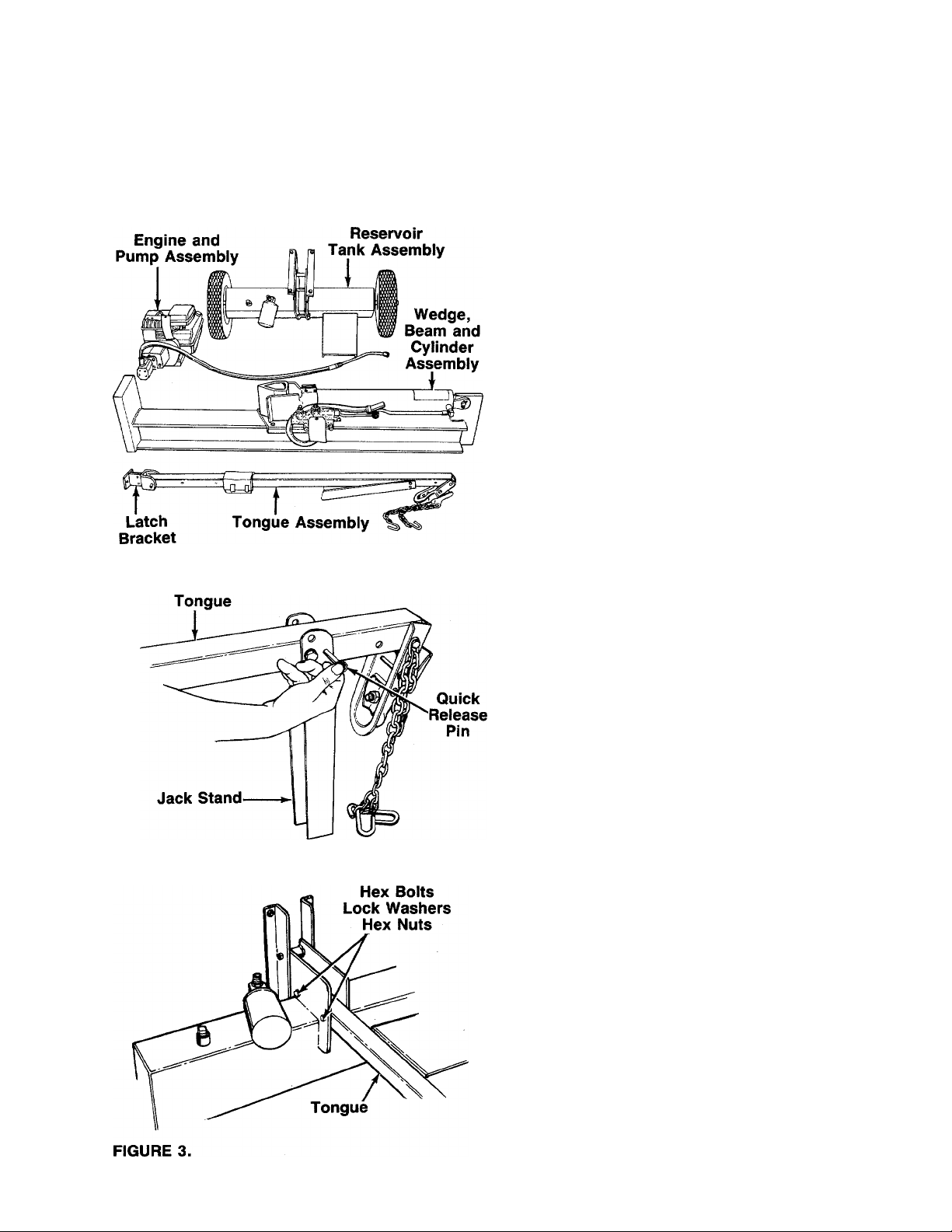
-Parts in Cartons (See figure 1)
Carton marked 1 of 2:
Reservoir Tank Assembly
Engine and Pump Assembly (Bolted to bottom of
carton)
Carton marked 2 of 2:
Tongue Assembly
Wedge, Beam and Cylinder Assembly
Tools Required for Assembly
(2) 9/16" Wrenches*
(1) 5/8" Wrench*
(1) 11/16" Wrench*
(2) 1/2" Wrenches*
(1) Adjustable Wrench
(1) Knife (to remove cable tie)
(1) Screwdriver
*Adjustable Wrenches may be used.
Other Materials Required for Assembly:
Engine Oil
Unleaded Gasoline (regular grade gasoline is an
acceptable substitute)
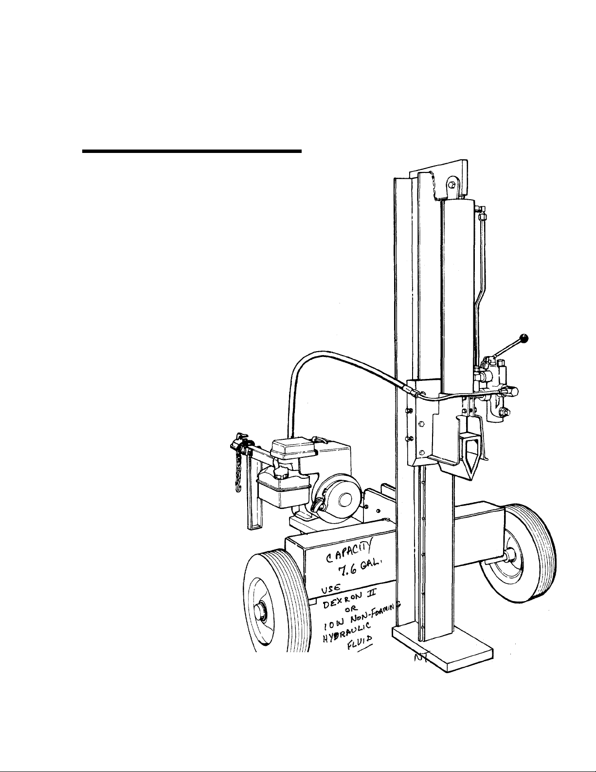
Approximately 7.6 Gallons of Dexron II Automatic
Transmission Fluid
FIGURE 2.
-ATTACHING TONGUE TO RESERVOIR TANK
1. The tongue is shipped with the jack stand already
attached to the tongue. The jack stand is in the
transport position. Remove the quick release pin.
Pivot the jack stand to the operating position (90°),
and secure with the quick release pin. See figure 2.
■^NOTE
If necessary, loosen the bolt which
holds the hitch to the tongue, and
pivot hitch out of the way.
2. Remove the latch bracket which has been
assembled to the other end of the tongue for ship
ping purposes only by removing another quick
release pin. Refer to figure 1. This bracket will be
reassembled to the beam on page 6. Replace the
quick release pin in the latch bracket.
—3. Remove the two hex bolts, lock washers and hex
nuts on the front of the reservoir tank. Two 9/16"
wrenches are required. Place the tongue in posi
tion, and secure with hardware just removed. See
figure 3.
Page 6
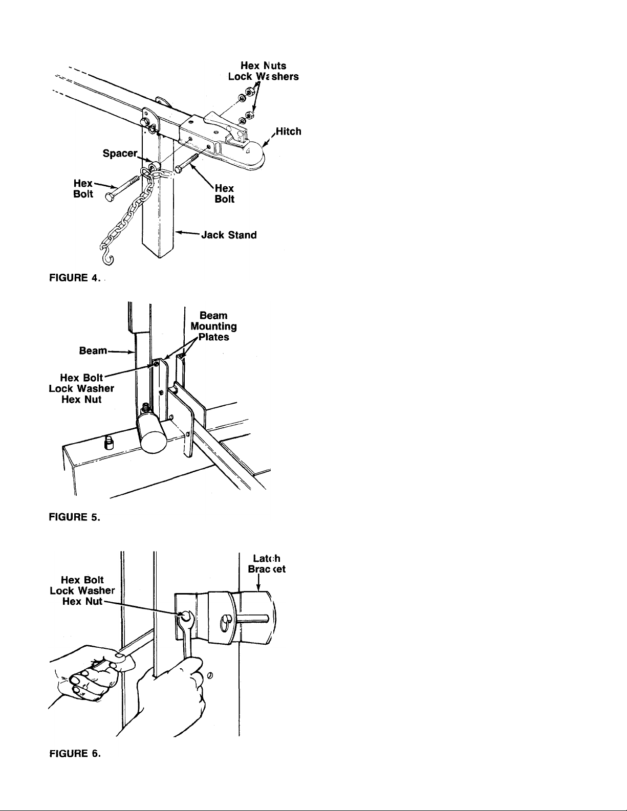
INSTALLING THE HITCH
1
Using two 9/16" wrenches, remove the two long
hex bolts, lock washers and hex nuts which are
assembled through the sides of the hitch and the
tongue. Do not remove the chain and spacer from
the one hex bolt.
2. Place the hitch in position on the end of the tongue.
—Secure with hardware just removed. See figure 4.
ATTACHING THE WEDGE, BEAM AND CYLINDER ASSEMBLY
1. Stand the wedge, beam and cylinder assembly
upright.
2. Remove the four hex bolts, lock washers and hex
nuts from the beam mounting plates. A 5/8" and
-------
an 11/16" wrench are required. See figure 5.
Roll the reservoir tank assembly in position against
3.
the beam. Secure the beam mounting plates to the
beam with hardware just removed. Tighten
securely.
ATTACHING THE LATCH BRACKET
1
Remove the two hex bolts, lock washers and hex
nuts from the beam, using two 1/2" wrenches.
With the beam still in the upright position, place
■the pivot latch on the beam as shown in figure 6.
Secure with hex bolts, lock washers and hex nuts
just removed. Tighten securely.
Page 7

FIGURE 7.
ATTACHING THE ENGINE AND PUMP ASSEMBLY
1. Using two 1/2" wrenches, remove the four hex
bolts, lock washers and hex nuts which secure the
base of the engine to the bottom of the shipping
carton.
2. Place the engine and pump assembly in position
on the engine mounting bracket as shown in figure
-------
7. Secure with hardware just removed. Tighten
securely.
ATTACHING THE CONTROL HANDLE
1. The control handle and the return hose are attach
ed to the metal pressure tube with a cable tie for
shipping purposes only. Cut and remove the cable
tie.
2. The bottom of the control handle is already at
tached to the valve with a cotter pin and clevis pin.
Remove the second cotter pin and clevis pin which
is attached to the valve only. Place the handle in
position, and secure using the second cotter pin
-------
and clevis pin. See figure 8.
Control
Valve
Filter
Head
FIGURE 9.
Suction-
Hose
Pump
ATTACHING THE HOSES Suction Hose
1. The suction hose is attached to the reservoir tank,
beneath the engine mounting plate. Loosen the
hose clamp on the free end of the hose using a
screwdriver.
2. Attach the end of the hose to the fitting on the bot-
-------
tom of the pump. See figure 9. Place the hose
clamp at the base of the fitting, and tighten
securely.
Return Hose
1. The return hose is attached to the bottom of the
valve. Loosen the hose clamp on the free end of
the hose using a screwdriver.
2. Attach the end of the hose to the fitting on top of
the filter head. See figure 9. Place the hose clamp
at the base of the fitting, and tighten securely.
Page 8

Pressure
Hose
FIGURE 10.
Control
Valve
Pressure Hose
The pressure hose is attached to the top of the pump.
-Route the hose as shown in figure 10. Place the metal
pressure tube in position on the fitting on top of controi valve. Secure with the compression nut on the
pressure tube, using an adjustable wrench.
FINAL ASSEMBLY
1. Make certain all nuts, bolts and hose clamps are
tightened securely.
2. Before operating the log splitter, make certain to
follow the “Initial Preparation” instructions in the
Operation Section.
OPERATION
INITIAL PREPARATION
1. Place log splitter on a firm, level surface. Fo' ver
tical operation, remove the quick release pin from
the latch bracket. Place the beam in the vertical
position. Place the quick release pin througi the
holes in the beam mounting plates anc the
brackets on the reservoir tank. See figure ' 1.
FIGURE 11.
b. Disconnect the spark plug wire. Prime the
pump by pulling the recoil starter, to turn the
engine over, approximately 10 times. Recon
nect the spark plug wire.
c. Start engine. Use the control handle to extend
the wedge to the far extended position. Leave
the wedge in this position (do not retract).
d. Refill tank to within 1V2" to 2" from the top of
the tank. Total capacity of system is approx
imately 7.6 gallons.
e. Now retract the wedge. Extend and retract the
wedge fully 10 to 12 complete cycles to remove
trapped air in the system (system is “self
bleeding”).
f. Refill the reservoir to within 1 Vz" to 2" from
the top of the tank. Much of the original fluid
has been drawn into the cylinder and hoses.
Make certain to refill the reservoir, to prevent
extreme damage to the hydraulic pump. Failure
to refill the tank will void your warranty.
2. Service engine with gasoline and oil as instructed
in the separate engine manual packed with your
log splitter.
3. Lubricate the beam area where splitting wedg e will
slide with engine oil (DO NOT USE GREASE).
Make certain to oil both front and back of the beam
face.
4. Fill the reservoir tank as follows.
a. Remove reservoir vent plug. See figur<i 11.
Using Dexron II automatic transmission fluid,
fill reservoir to the top. Replace vent plug
securely.
NOTE
Some fluid may overflow from the
vent plug as the system builds heat
and the fluid expands and seeks its
own level.
WARNING
A
Do not operate the log splitter without
the proper amount of transmission
fuild in the reservoir tank.
Page 9

BEFORE STARTING
Before each use, check the following:
1. Place log splitter on a firm, level surface. For ver
tical operation, remove the quick release pin from
the latch bracket. Place the beam in the vertical
position. Place the quick release pin through the
holes in the beam mounting plates and the
brackets on the reservoir tank. See figure 11.
2. Remove the vent plug and check the fluid level.
Fluid level should be 1 Vz" to 2" from the top of the
tank.
■{^IMPORTANT
Reservoir tank must be full as
instructed. Low fluid level will damage
the pump and void your warranty.
3. Lubricate the beam area where splitting wedge will
slide with engine oil (DO NOT USE GREASE).
Make certain to oil both front and back of the beam
face.
4. Fill gasoline tank as instructed in separate engine
manual.
5. Attach spark plug wire to spark plug.
7. If weather is cold, run wedge up and down beam
6 to 8 times to circulate the hydraulic fluid, which
will warm and thin the fluid.
TO STOP ENGINE
1. Move throttle control lever to OFF position.
2. Disconnect spark plug wire from spark plug to pre
vent accidental starting while equipment is unat
tended.
TO START ENGINE
1. Place throttle control lever on the engine in FAST
position. See figure 12.
2. Place choke lever in CHOKE position.
NOTE
A warm engine may not require choking.
Grasp starter handle and pull rope out slowly until
3.
engine reaches start of compression cycle (rope
will pull slightly harder at this point). Let the rope
rewind slowly.
Pull rope with a rapid, continuous, full arm stroke.
4.
Keep a firm grip on the starter handle. Let the rope
rewind slowly. Do not let starter handle snap back
against starter.
Repeat preceding instructions 3 and 4 until engine
fires. When engine starts, move choke lever
halfway between CHOKE and RUN.
Move throttle control lever to IDLE position for a
few minutes warm-up. Gradually move choke lever
to RUN position as engine warms up.
NOTE
In order to idle smoothly, a new
engine may require 3 to 5 minutes
running above slow idle speed. Idle
speed has been adjusted to be correct
after this break-in period.
USING THE LOG SPLITTER
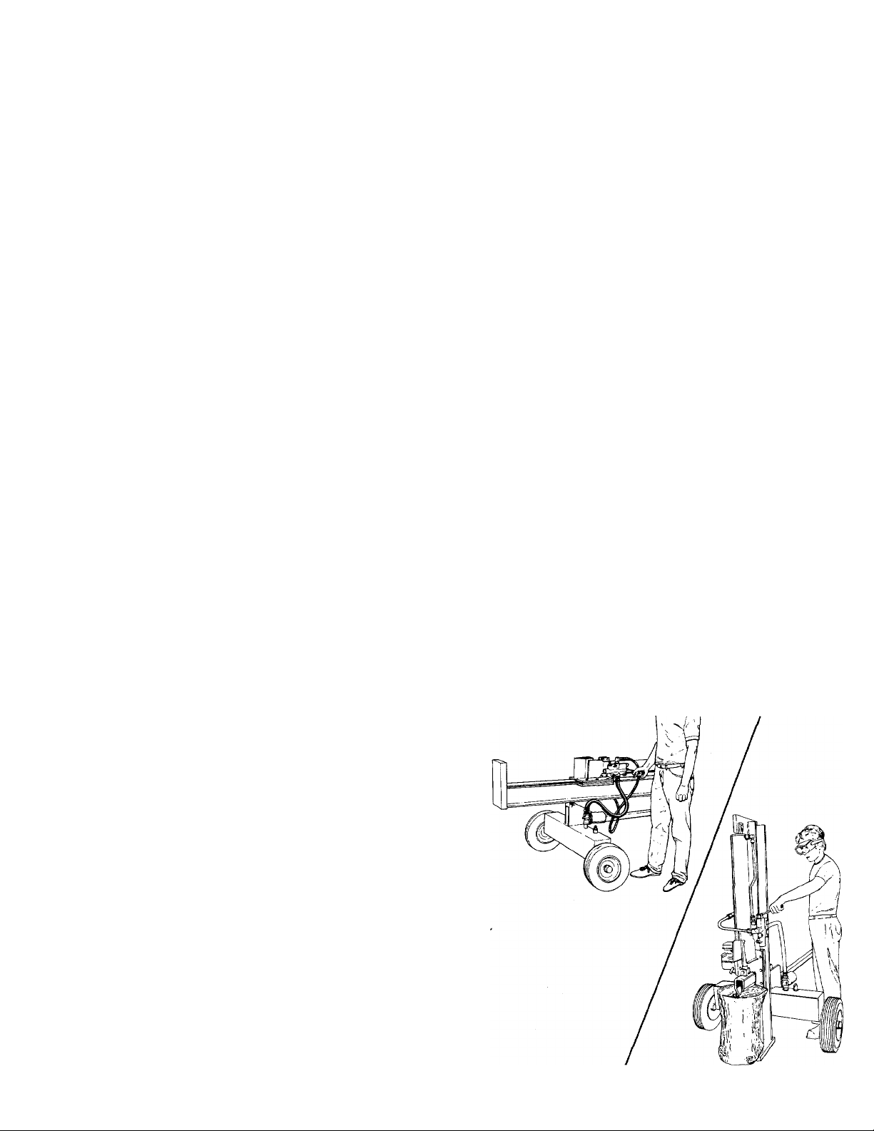
Use the log splitter only on a level, hard surface.
Never stand next to the splitting wedge when
operating the log splitter. Always stand behind the
reservoir tank. See figures 13 and 14. Never attempt
to cut a log in half sideways. Always split the log
lengthwise. Maximum length of log to be split is 24".
A
Always use the log splitter in the
vertical position only when splitting
heavy logs.
The control handle has three positions:
FORWARD—Push the control handle down for vertical
operation, push it forward for horizontal operationsplitting wedge moves toward the end plate. Con
trol handle will return to neutral position as soon as
handle is released.
NEUTRAL (Middle position)—Splitting wedge stops
in place.
REVERSE—Push the control handle upward for ver
tical operation, push it toward the rear for horizontal
operation—Splitting wedge returns. The control han
dle will lock in the reverse position, and will return
to neutral automatically when the reverse stroke is
complete.
Page 10

5. Move the control handle to reverse position to
return the splitting wedge.
FIGURE 13.—Vertical Operation
A
WARNING
If the fluid becomes excessively hot at
any time during operation, stop the unit
and allow the fluid to cool down. Maxi
mum performance will not be obtained
from your log splitter if the fluid is too
hot. Use extreme caution as contacting
hot fluid could result in serious personal
injury.
TO TRANSPORT LOG SPLITTER
1. Lower the beam to its horizontal position. Make
certain the latch bracket is latched securely around
the tongue and secured with the quick release pin.
2. Remove the quick release pin which secures the
jack stand. Pivot it up against the tongue, and
secure with the quick release pin.
3. Attach the hitch to a towing vehicle, making cer
tain to latch securely. Attach the safety chains to
the towing vehicle.
TO OPERATE LOG SPLiTTER:
1. Set throttle at maximum speed.
2. Place the log upright, on top of end plate for ver
tical operation, and on top of beam for horizantal
operation.
3. Push the control handle to forward position until
the splitting wedge just contacts the log. Release
the control handle.
4. Step behind the reservoir tank (see figures 13
or 14) and push the control handle in forward Dosi-
tion until the log is split.
ADJUSTMENT
SPLITTING WEDGE
As normal wear occurs, periodically adjust the bolts on
the slide plate (beneath the splitting wedge) as follows
to eliminate the excess space between the wedge plate
and the beam. See figure 15.
Hex Bolts
Bolts
FIGURE 15.
1. Loosen the three hex bolts on top of the slide plate
(beneath the splitting wedge).
10
Page 11

Back the two adjustment bolts on the side of the
slide plate out slowly until the wedge assembly will
slide on the beam. Tighten the lock nuts securely
against the base of the slide plate to hold the bolts
in this position.
Retighten the three hex bolts on top of the slide
3.
plate.
CARBURETOR ADJUSTMENT
A
If any
engine
(e.g. carburetor), keep clear of all moving
parts. Be careful of heated surfaces and
muffler.
Minor carburetor adjustment may be required to com
pensate for differences in fuel, temperature, altitude or
load. Improper adjustment will cause stalling when split
ter is under load, hard starting and higher fuel con
sumption.
Refer to the separate engine manual packed with your
log splitter for carburetor adjustment information.
A DIRTY AIR CLEANER WILL CAUSE
ENGINE TO RUN ROUGH. BE CERTAIN
AIR CLEANER IS CLEAN AND AT
TACHED TO THE CARBURETOR
BEFORE ADJUSTING CARBURETOR.
DO NOT MAKE UNNECESSARY
ADJUSTMENTS. FACTORY SETTINGS
ARE SATISFACTORY FOR MOST
APPLICATIONS AND CONDITIONS.
adjustments are made to the
while the engine is running
WARNING
NOTE
automatic transmission fluid, as instructed in the “In
itial Preparation” section of this manual, page 8. Also,
make certain to change the hydraulic fitter.
NOTE
Drain the fluid and flush the reservoir
tank and hoses with kerosene whenever
any repair work is performed on the
tank, hydraulic pump or valve. Con
taminants in the fluid will damage the
hydraulic components. (Should be per
formed by an authorized service dealer.)
t- warning I
A
Use extreme caution when working with
kerosene, as it is an extremely flammable
fluid.
HYDRAULIC FILTER
Change the hydraulic filter every 50 hours of operation.
Use only a 10 micron hydraulic filter. Order part number
723-0405.
BEAM AND SPLITTING WEDGE
Lubricate both sides of the beam where it contacts the
splitting wedge with engine oil before each use to ob
tain years of service. However, normal wear will occur.
The wedge plate on the log splitter is designed so the
gibs on the side of the wedge plate can be easily re
moved and rotated and/or turned over for even wear.
Make certain to readjust the adjustment bolts so wedge
moves freely, but no excess space exists between the
wedge plate and beam.
HOSE CLAMPS
Check the hose clamps on the suction hose (attached
to bottom of the pump) for proper tightness before each
use. Check the hose clamps on the return hose at least
once a season.
MAINTENANCE
Ac
Always stop the engine and disconnect
the spark plug wire before performing
any maintenance or adjustments.
RESERVOIR FLUID
Check the hydraulic fluid level in the log splitter reser
voir tank before each use. Fluid level should be 1-1/2"
to 2" from the top of the tank.
Change the hydraulic fluid in the reservoir every 100
hours of operation. Disconnect the suction hose from
the bottom of the reservoir tank, and drain the fluid in
to a suitable container. Refill using only Dexron II
WARNING }
ENGINE
Refer to the separate engine manual for all engine
maintenance instructions.
Maintain engine oil as instructed in the separate
engine manual packed with your unit. Read and follow
instructions carefully.
Service air cleaner every 25 hours under normal con
ditions. Clean every few hours under extremely dusty
conditions. Poor engine performance and flooding
usually indicates that the air cleaner should be ser
viced. To service the air cleaner refer to the separate
engine manual packed with your unit.
The spark plug should be cleaned and the gap reset
once a season. Spark plug replacement is recommend
ed at the start of each season; check engine manual
for correct plug type and gap specification.
11
Page 12

Clean the engine regularly with a cloth or brusli. Keep
the cooling system (blower housing area) clear to per
mit proper air circulation which is essential to engine
performance and life. Be certain to remove all dirt and
combustible debris from muffler area.
FLEXIBLE PUMP COUPLER
The flexible pump coupler is a nylon “spider’ insert,
located between the pump and engine shaft. The align
ment is very critical. Over a period of time, the coupler
will harden and deteriorate. For a replacement flexible
pump coupler, order part number 717-0891.
WARNING
A
Never hit the pump shaft in any manner,
as any blow will cause permanent
damage to the pump.
When replacing the flexible pump coupling, p roceed
as follows.
1. Place the coupling half onto the engine shal t. Make
certain there is clearance between the CDupling
half and the engine. Tighten the set screw.
2. Mount the pump onto the coupling support bracket.
Tighten securely.
3. Carefully slide coupling half onto pump shalt (make
certain set screw is loose). Slide the key inio place
on the shaft.
4. Install the nylon “spider” insert into coupling half
on the engine shaft.
5. Place the coupling shield in position on he hex
bolts. Rotate the keyway on the pump sh aft so it
is toward the bottom.
6. Attach the coupling support bracket to ihe hex
bolts, carefully sliding the coupling half e ver the
“spider” insert. Secure coupling shield and coup
ling support bracket with lock washers e nd hex
nuts. Tighten securely.
7. Adjust the two coupling halves (steel) so there is
between .010" and .060" clearance between the
two halves (at least the thickness of a ma chbook
cover, up to 1/16" maximum). See figure 16.
Tighten the set screw in the coupling hab on the
pump shaft.
PUMP
TIRE PRESSURE
Check sidewall of tire for manufacturer’s recommended
maximum tire pressure. If this information does not ap
pear on your tire, maximum tire pressure under any cir
cumstances is 30 p.s.i. Equal pressure should be
maintained on both tires.
INSTALLATION OF TIRE TO RIM
A
The following procedure must be fol
lowed when removing or installing a
tire to the rim.
1. Be certain rim is clean and free of rust.
2. Lubricate both the tire and rim generously.
3. Never inflate to over 30 p.s.i. to seat beads. Ex
cessive pressure when seating beads may cause
tire/rim assembly to burst with force sufficient to
cause serious injury.
I WARNING {
OFF-SEASON STORAGE
To avoid engine problems, the fuel system should be
emptied before storage of 30 days or longer. Follow
these instructions.
1. Drain the fuel tank. Start the engine, and let it run
until the fuel lines and carburetor are empty.
A
DO NOT DRAIN FUEL WHILE
SMOKING, OR IF NEAR AN OPEN FIRE.
WARNING
NOTE
Make certain proper clearance is
tained before tightening set screw.
ob-
2. Drain all the oil from the crankcase (this should be
done after the engine has been operated and is
still warm) and refill the crankcase with fresh oil.
12
Page 13

3. Protect the inside of the engine for storage as
follows.
Remove spark plug, pour approximately V2 ounce
(approximately one tablespoon) of engine oil into
cylinder and crank slowiy to distribute oil. Replace
spark plug.
4. Clean the engine and the entire log splitter
thoroughly.
5. Wipe unit with an oiled rag to prevent rust,
especially wedge and beam.
NOTE
When storing any type of power
equipment in an unventilated or metal
storage shed, care should be taken to
rustproof the equipment by coating with
a light oil or silicone.
6. The tongue can be removed and reattached in an
upright position as shown in figure 17 to take less
space when storing.
7. Store unit in a clean, dry area.
FIGURE 17.
13
Page 14

Trouble Shooting Guide
Trouble
Engine fails to start
Engine runs erratic
Engine overheats
Possible Cause (s)
1. Fuel tank err pty, or stale fuel.
2. Blocked fuel line.
3. Spark plug vire disconnected.
4. Faulty spark plug.
1. Unit running on CHOKE.
2. Spark plug wire loose.
3. Blocked fuel line or stale fuel.
4. Water or dirt in fuel system.
5. Dirty air cleaner.
6. Carburetor ojt of adjustment.
1. Engine oil level low.
2. Air flow restricted.
3. Carburetor n3t adjusted properly.
Corrective Action
1. Fill tank with clean, fresh gasoline.
2. Clean fuel line.
3. Connect wire to spark plug.
4. Clean, adjust gap or replace.
1. Move choke lever to OFF position.
2. Connect and tighten spark plug
wire.
3. Clean fuel line; fill tank with clean
fresh gasoline.
4. Drain fuel tank. Refill with fresh
fuel.
5. Clean air cleaner as instructed in
separate engine manual.
6. Adjust carburetor (see Carburetor
Adjustment in separate engine
manual).
1. Fill crankcase with proper oil.
2. Remove blower housing and
clean as instructed in
separate engine manual.
3. Adjust carburetor (see Carburetor
Adjustment in separate engine
manual).
Will not split logs
Leaking cylinder
Reservoir flu d level low.
1. Broken seals.
2. Scored cylinder.
Check and fill reservoir tank as
instructed in Operation section
of this manual.
1. Replace seals.*
2. Replace cylinder.*
• «r
NOTE: For repairs beyond the minor adjustments listed above, please contact your nearest authorized service dealer.
* Should be performed by an authorized s >rvice dealer only.
14
Page 15

HOW YOUR LOG SPLITTER OPERATES
Gear Section
THE PUMP
A two-stage log splitter pump has one large and one
small ^ar section, using common inlet and outlet ports.
Below a preset pressure (called unloading pressure)
a chegk valve between the two gear sections allows
both flows to combine. Together, the two gear sections
create a large volume flow which produces rapid
cylinddft»novement under low load conditions.
Above tiiloading pressure, a pilot pressure line (which
simulates actual pressure at the cylinder) activates the
unloading valve, which causes the flow to bypass the
large gear section and return to the pump inlet area.
The small gear section is now operating alone, and will
generate the higher pressure necessary for the actual
log splitting operation.
The original factory setting for the unloading valve is
designed to provide maximum flow while remaining
below engine stalling load. Note: Splitting capability
is not affected by the setting of the unloading valve.
Do not attempt to adjust or reset it without a
pressure gauge (should be performed by an
authorized service dealer only).
THE DIRECTIONAL VALVE AND CYLINDER
From the pump, oil flows to a four way, three position
directional valve. At the neutral position this valve
directs the flow back to the oil reservoir, bypassing the
cylinder. When the directional valve is directing the flow
to the back of the cylinder, the cylinder rod extends
quickly until it meets significant resistance. Upon
reaching unloading pressure, movement of the shaft
will slow but will continue forward, if the pressure
reaches a preset maximum (called reliefValve pressure)
the relief valve, located within the directional valve, wiN
allow the flow to bypass the cylinder and return to the
reservoir. This can happen when the cylinder rod meets
excessive resistance, or when it reaches the end of its
stroke and can move no farther.
Note: Never operate at relief valve pressure for more
than a few seconds.
When the directional valve is directing the flow to the
front of the cylinder, the rod will retract quickly since
it is encountering no resistance. The relief valve will
momentarily bypass the flow at the end of the return
stroke but the directional valve should then automatical
ly return to the neutral position, directing the flow direct
ly into the reservoir. This serves to protect the pump
from possible damage due to prolonged operation at
relief valve pressure.
Because of the potential for system damage, the relief
valve is carefully and precisely preset by the
manufacturer.
Note: The user should not attempt to adjust or
change the setting of the relief valve.
OPERATIONAL PROBLEMS
If you have trouble with your log splitter, please refer
to the Hydraulic Trouble Shooting Guide on page 18.
Note: Readjustment of valves or disassembly of
pump should be performed by an authorized ser
vice dealer only.
15
Page 16

I
I
PRO/20 (Model 620)
6PEftfa\0N VR£SS\}KE
asoó TO 30ÙO Psi
HINOTE
Specifications subject to change without notice or
obligation.
■M
16
Page 17

PRO/20 (Model 620)
PARTS LIST FOR MODEL 620 LOG SPLITTER
lEF.
»lO.
10
11
Ir12 727-mS» N
14
15
16
17 710-0409
18 710-3160
19
20
21 736-0119
22
23 737-0236
24 750-0739
25
|26 735-0639
27
29 723-0406
30 726-0146
31 727-0309 Return Hose %" I.D. x 30" Lg.
32
33 712-0299 Hex Castle Nut 3/4-I6 Thd.
34
35 734-0873 Hub Cap
36
37
38 736-0351
39
40
41 710-0514 Hex Bolt 3/8-16 X 1" Lg.-Gr. 5
42
43 711-0820
44 712-0123
45
46 712-3067 Hex Patch L-Nut 7/16-20 Thd.
47 736-0119 L-Wash. 5/16" I.D.*
48 736-0169
PART
NO.
1 736-0119
2 710-0117
710-0237
3
4 710-0363
5 712-0123
714-0122 Sq.-Key 3/16 x .75
6
7 717-0891
717-0936
8
9 719-0278
CODE
L-Wash. 5/16" I.D.*
Hex Bolt 5/16-24 x 1" Lg.
Hex Bolt 5/16-24 x .62" Lg.
Hex Bolt 5/16-24 x 4" Lg.
Hex Nut 5/16-24 Thd.
Flexible Coupling
N Two Volume Pump
Coupling Shield
DESCRIPTION
726-0132 Hose Clamp 5/8"
727-0427 N Suction Hose 1" I.D.
High Pressure Hydraulic
0433
Hose W 67 ’'SUi^fiL CPOO\
781-0097 Rear Coupling Support Brkt.
781-0098
781-0337
Front Coupling Support Brkt.
Tank Ass’y. Complete
Hex Bolt 5/16-24 x 1.75" Lg.*
Hex Bolt 1/2-20 X 4" Lg.—Gr. 5
712-0123
712-0333
Hex Nut 5/16-24 Thd.*
Nut 1/2 BL NF-20
L-Wash. 5/16" I.D.*
736-0921 L-Wash. 1/2" I.D.*
Pipe Plug
N Pivot Bushing .75" O.D.
781-0312 N
Strainer Ass’y.
Spark Plug Cover
723-0405 Filter Element
Filter Head
Adjustable Hose Clamp
737-0235
3A" Dia. Hose Barb
714-0162 Cotter Pin 5/32"
734-1016 Wheel Ass’y. Comp.
734-0872
Tire Only
734-1017 Rim Only
734-0255
Air Valve
741-0107 Roller Brg. W
FI-Wash. .760" I.D. X 1.5" O.D.
750-0442 Spacer .75" I.D. x 1.12" O.D.
710-0117 Hex Bolt 5/16-24 x 1" Lg.*
710-3029
Hex Bolt 7/16-20 x 1.25" Lg.—
Gr. 5
Quick Release Pin
Hex Nut 5/16-24 Thd.*
712-3017 Hex Nut 3/8-16 Thd.—Gr. 5
L-Wash. 3/8" I.D.* Lmíü^S&E aJcT
REF.
NO.
PART
NO.
CODE DESCRIPTION
49 736-0171 L-Wash. 7/16" I.D.*
781-0315 N Beam Mtg. Plate
50
51 781-0334
52
781-0340 Vertical Beam Ass’y.
N
Beam Latch Bracket
57 5 H.P. Engine
60 717-0885B
61 714-0203
62
715-0206
N
Hydraulic Cylinder 4" Dia.
N
External Cotter Pin
N Cylinder Mtg. Pin
63 717-0886 Control Valve—3000 PSI
64 727-0307
65 727-0440
66 737W7-I
•N
Metal Pressure Tube Vz" O.D.
Pressure Tube V2" Dia.
90° Solid Male Adapter
< 67 737-0192 90° Solid Male Adapter
68 737-0235 3/4" Dia. Hose Barb
69 737-0238 Pipe Nipple Vz NPT
73
710-1010 Bolt Vz X 3
74 710-1018
Hex Bolt Vz-20 x 2.75" Lg.—
Gr. 8
75 710-1032 N
76 712-0239
77 712-0333
Hex Bolt 3/8-24 x 1.5" Lg.
Hex L-Nut Vz-20 Thd.
Nut Vz BL NF-20 Thd.
78 712-3001 Hex Jam Nut 3/8-24 Thd.—Gr. 5
736-0921
79
80 750-0743
81 781-0323 N
L-Wash. Vz" I.D.
N
Spacer Vz" I.D. x 3/4" O.D.
Wedge Mtg. Ass’y.
87 781-0345 N Pusher Back Plate
88 781-0350 N
89 781-0351
781-0352 N
90
91 781-0356 N
710-0521
95
710-3130
96
Fixed Side Gib
N
Adj. Gib 2" Lg.
Adj. Gib Shim 10" Lg.
Floating Gib Plate
Hex Bolt 3/8-16 X 3" Lg.-Gr. 8
Hex Bolt 3/8-16 X 3.25" Lg.—
Gr. 8
97 711-0820 Quick Release Pin
99 712-0375
Hex L-Nut 3/8-16 Thd.
100 712-0798 Hex Nut 3/8-16 Thd.*
101 713-0338 Chain—Tow Hitch
102
727-0311
Hitch Coupler
103 736-0169 L-Wash. 3/8
104
736-0185 FI-Wash. .406" I.D. x .75
750-0507
105
Spacer .38" I.D. x .625" O.D.
106 781-0316 Tongue Tube
781-0358
107
112 710-0831
113 710-3144
114 712-0430
750-0745
115
781-0168A
116
117
720-0231
Jack Stand Ass’y.
Hex Bolt 3/8-16 X 5.5" Lg.
Hex Bolt 3/8-16 X 2" Lg.-Gr. 5
Hex Insert L-Nut 3/8-16 Thd.
Spacer 4" Lg.
N Stripper Half
Ball Knob i
118 747-0709 Control Hand\eMAh'
uKiLs^s ató caen:
X7b
‘For faster service obtain standard nuts, bolts and washers locally.
If these items cannot be obtained locally, order by part number and
size as shown on parts list.
17
NOTE: The engine is not under warranty by
the log splitter manufacturer... If repairs or
service is needed on the engine, please
contact your nearest author
ized engine service outlet.
Check the “Yellow Pages” of
your telephone book under
“Engines—Gasoline.”
Find It Fast
In The
Yellow Pages
Page 18

HYDRAULIC TROUBLE SHOOTING GUIDE
Problem
Cylinder rod will not
move
Slow cylinder shaft
speed while
extending and
retracting
Engine runs but
wood will not split,
or wood splits too
slowly
Probable C ause(s)
A Broken driveshaft
B Loose shaft coupling
C Gear sections damaged
D Damaged relief v< live
E Hydraulic lines blocked
F Too little oil to pu np
G Damaged directio lal valve
H Blocked directional valve
A Gear sections damaged
B Excessive pump i ilet vacuum
C Slow engine speed*
D Damaged relief Vc Jve
E Too little oil to pu Tip
F Air in oil
G Directional valve baking internally
H Internally damaged cylinder
A Small gear section damaged
B Pump check valves leaking
C Excessive pump i ilet vacuum
D Low relief valve sotting
E Too little oil to pu np
F Air in oil
G Directional valve 1 saking internally
H Overloaded cylinder
1 Internally damaged cylinder
Corrective Action
A Return pump for authorized repair
B Correct engine/pump alignment as necessary
C Return pump for authorized repair
D Return directional valve for authorized repair
E Flush and clean hydraulic system
F Add oil to reservoir
G Return directional valve for authorized repair
H Flush and clean hydraulic system; return
directional valve for authorized repair
A Return pump for authorized repair
B Make certain pump inlet hoses are clear
and unblocked—use short, large
diameter inlet hoses
, C Return erigine for authorized repair ; . X
D -Returri directional valve for authorized’r^iiair
E Add oil to reservoir
F Add oil, clean reservoir, make certain oil
return tube is below oil level
G Return directional valve for authorized repair
H Return cylinder for authorized repair
A Return pump for authorized repair
B Return pump for authorized repair
C Make certain pump inlet hoses are
clear and unblocked; use short, large
diameter inlet hoses
D Adjust valve while using pressure gauge*
E Add oil to reservoir
F Add oil, clean reservoir, make certain oil
return tube is below oil level
G Return directional valve for authorized repair
H Do not attempt to split wood against the grain
1 Return cylinder for authorized repair
Engine stalls during
splitting
Engine will not turn
or stalls under low
load conditions
Leaking pump shaft
seal
A Low horsepower/v reak engine
B High relief valve setting
C High unloading vs Ive setting
D Overloaded cylinder
A Engine/pump misalignment
B Frozen or seized pump
C Low horsepower/v 'eak engine
D Hydraulic lines blocked
E Blocked directions;! valve
A Broken driveshaft
B Engine/pump misalignment
C Gear sections damaged
D Poorly positioned shaft seal
E Plugged oil breatf er
* Should be performed by an authorized service dealer only.
A Return engine for authorized repair
B Adjust valve while using pressure gauge*
C Adjust valve while using pressure gauge*
D Do not attempt to split wood against the grain
A Correct alignment as necessary
B Return pump for authorized repair
C Return engine for authorized repair
D Flush and clean hydraulic system
E Flush and clean hydraulic system; return
directional valve for authorized repair
A Return pump for authorized repair
B Correct alignment as necessary
C Return pump for authorized repair
D Return pump for authorized repair
E Make certain reservoir is properly vented
18
Page 19

ч
Page 20

18 MONTH LIMITED WARRANTY
NON-COMMERCIAL
NON-TRANSFERABLE
Limited to Modeis PRO/20 and 424/LCD/22 Log Spiitters
For 18 months from the date of original retail purchase, DUERR INC. will either repair or replace,
at its option, free of charge, F.O.B. actory or authorized service firm, any part or parts found
to be defective in material or worknr anship. Transportation charges for the movement of any
power equipment unit or attachment are the responsibility of the purchaser. Transportation
charges for any parts submitted for eplacement under this warranty must be paid by the pur
chaser unless such return is requested by DUERR INC.
Warranty on units used commercia ly is limited to ninety (90) days.
This warranty will not apply to any part which has become inoperative due to normal wear,
misuse, excessive use, accident, neglect, improper maintenance, alterations, modifications,
or unless the unit has been operated and maintained in accordance with the instructions fur
nished. This warranty does not apply to the engine, pump, cylinder^rcomponent parts thereof.
Please refer to the applicable mam facturer’s warranty on these items.A^^^,^^.
Warranty service is available through your local authorized service dealer or distributor. If you
do not know the dealer or distributor n your area, please write to the Customer Service Depart
ment of DUERR INC.
The return of a complete unit will not be accepted by the factory unless prior written permission
has been extended by DUERR, INC.
This warranty gives you specific legal rights. You may also have other rights which vary from
state to state.
XioMGsnd OR. 'ResitiE.fJTiM- u)wiRMoir/ » \2 Wi.
Corntne-RaNu rrfs^
'Pump i yft. Pu£vDfflrel ^
Mk,UJ£ - 3 VRJS. FRom PUft.. ‘bATE
Unit Purchased F rom;
Dealer’s Name
Address
____________
City, State
______
__________
We stand behind our products’
DUERR INC. • MEAD, WASHINGTON 99021
(509) 238-6124
XXE&KilDLESS OP TYPE Of
USA£E
FORM NO. 770-6745D
(R880725)
 Loading...