

Page 1
FIFTY CENTS
owmR
ASSEMBLY
OPERATION
MAINTENANCE
PARTS LIST
Important:
Read Safety Rules and
AHUAL
Model No.
248-650A
Instructions Carefully
POWER
SHREDDER
PRINTED IN U.S.A.
FORM NO. 770-7466
Page 2

LIMITED WARRANTY
For one year from the date of original retail purchase, MTD PRODUCTS INC will either
repair or replace, at its option, free of charge, F.O.B. factory or authorized service firm,
any part or parts found to be defective in material or workmanship. Transportation charges
under this warranty must be paid by the purchaser unless return is requested by MTD
PRODUCTS INC.
This warranty will not apply to any part which has become inoperative due to misuse,
excessive use, accident, neglect, improper maintenance, alterations, or unless the unit
has been operated and maintained in accordance with the instructions furnished. This
warranty does not apply to the engine, motor, battery, battery charger or component parts
thereof. Please refer to the applicable manufacturer’s warranty on these items.
This warranty will not apply where the unit has been used commercially.
Warranty service is available through your local authorized service dealer or distributor. If
you do not know the dealer or distributor in your area, please write to the Customer Service
Department of MTD.
The return of a complete unit will not be accepted by the factory unless prior written
permission has been extended by MTD.
This warranty gives you specific legal rights. You may also have other rights which vary
from state to state.
WARNING TO PURCHASERS
OF INTERNAL COMBUSTION ENGINE EQUIPPED
MACHINERY OR DEVICES IN THE STATE OF CALIFORNIA
The equipment which you have just purchased does not have a spark arrester. If this equipment is used on
any forest covered land, brush covered land, or grass covered unimproved land in the State of California,
before using on such land, the California law requires that a spark arrester be provided. In addition, spark
arrester is required by law to be in effective working order. The spark arrester must be attached to the
exhaust system and comply with Section 4442 of the California Public Resources Code.
Page 3

I M PO RTANT
It is suggested that this manual be read in its entirety before attempting to assemble or operate. Keep this
manual in a safe place for future reference and for ordering replacement parts.
This unit is shipped WITHOUT GASOLINE or OIL. After assembly, see operating section of this manual for
proper fuel and amount.
SAFE OPERATION PRACTICES FOR POWER SHREDDERS
TRAINING
The operator should become fully familiar
1
with all of the different sections of the Own
er’s Manual before attempting to operate this
equipment.
2. Children must never be allowed to operate
this equipment.
3. This equipment should never be operated in
the vicinity of children, pets or other persons.
4. Never run your machine in an enclosed area
as the exhaust from the engine contains
carbon monoxide, which is an odorless,
tasteless and a deadly poison gas.
5. Never allow your hands or any part of your
body or clothing inside the feeding chamber,
discharge chute, or near any moving part
while the machine or engine is running.
6. If it is necessary for any reason to inspect or
repair the feeding chamber or any part of the
machine where a moving part can come in
contact with your body or clothing, stop the
machine, allow it to cool, and disconnect the
spark plug wire from the spark plug before
attempting such inspection or repair.
PREPARATION
1. It is recommended that the operator of this
equipment obtain and wear safety glasses at
all times while operating the machine.
2. Wear proper apparel, avoid wearing loose
fitting clothing.
3. This machine should be operated only upon
an earthen level surface.
4. Assure that all screws, nuts and bolts and
other fasteners are properly secured.
OPERATION
When feeding shreddable material into this
1.
equipment, be extremely careful that pieces
of metal, rocks, bottles, cans or other foreign
objects are not included.
If the cutting mechanism strikes any foreign
2.
object or if your machine should start making
an unusual noise or vibration, immediately
stop the engine and disconnect the spark plug
wire from the spark plug. Allow the machine
to stop and take the following steps:
A. Inspect for damage.
B. Replace or repair any damaged parts.
C. Check for any loose parts and tighten to
assure continued safe operation.
3. The engine must be kept clean of debris and
other accumulations.
4. Do not allow an accumulation of processed
material to build up in the discharge area as
this will prevent proper discharge and can
result in kick-back from feed opening.
5. Never allow your hands or any other part of
your body or clothing inside the feeding
chamber, discharge chute or near any moving
part while the engine is running.
6. Keep all guards and deflectors in place and in
good working condition to assure continued
safe operation.
7. Always stand clear of the discharge area when
operating this machine.
8. Keep your face and body back from the feed
opening to avoid accidental bounce back of
any material.
9. Do not over-reach. Keep proper balance and
footing at all times.
10. The engine governor settings on your
machine must not be altered, changed, or
tampered with. The governor controls the
maximum safe operating speeds and protects
the engine and all moving parts from damage
caused by overspeed.
11. Do not transport machine while engine is
running.
MAINTENANCE AND STORAGE
1. When this equipment is stopped for servicing,
inspection, storage or to change an acces
sory, make sure the spark plug wire is
disconnected from the spark plug. The
machine should be allowed to cool down
before making such inspection, adjustments,
service, etc. Maintain your machine with care
and keep it clean for the best and continued
safe operation.
2. When not in use, your machine should be
stored out of the reach of children. Keep
where gasoline fumes will not reach an open
flame or spark. For long periods of storage,
the gasoline should be drained and disposed
in a safe manner. Always allow the machine
to cool before storing in any enclosure.
Page 4

PRE-ASSEMBLY
NOTE
The right and left side of your shred
der is determined from operator’s
position.
Before any step is undertaken, the instructions for
that step should be read through.
§ m
rrji rrri rrrt q™
TOOLS REQUIRED:
1. (1) 7/16” Open End or Box Wrench
2. (1) 1/2” Open End or Box Wrench
3. (1) Adjustable Wrench.
MATERIALS REQUIRED:
1. Funnel (for gas and oil—NOTE: Do not mix).
2. S.A.E. 30 011—23/4 pints.
3. Gas (regular).
4. Cleaning rag.
PARTS IN CARTON
B
rm nni ETii mi
FIGURE 2.
ASSEMBLY
FIGURE 1.
NOTE
The letters listed below will be re
ferred to throughout the following
text for easier hardware identifica
tion.
LIST OF CONTENTS IN HARDWARE PACK:
A (3) Hex washer head self threading screws
B (4) Hex screws V4-20 X V2” long
C (4) Hex center locknuts ■'A-20 thread
D (4) Hex screws V4-2O x V2” long
E (4) Lockwashers ■'A” screw
F (4) Hex center locknuts Va-20 thread
INSTRUCTIONS
1. Remove the shredder, parts pack and all
literature from the carton before discarding
carton.
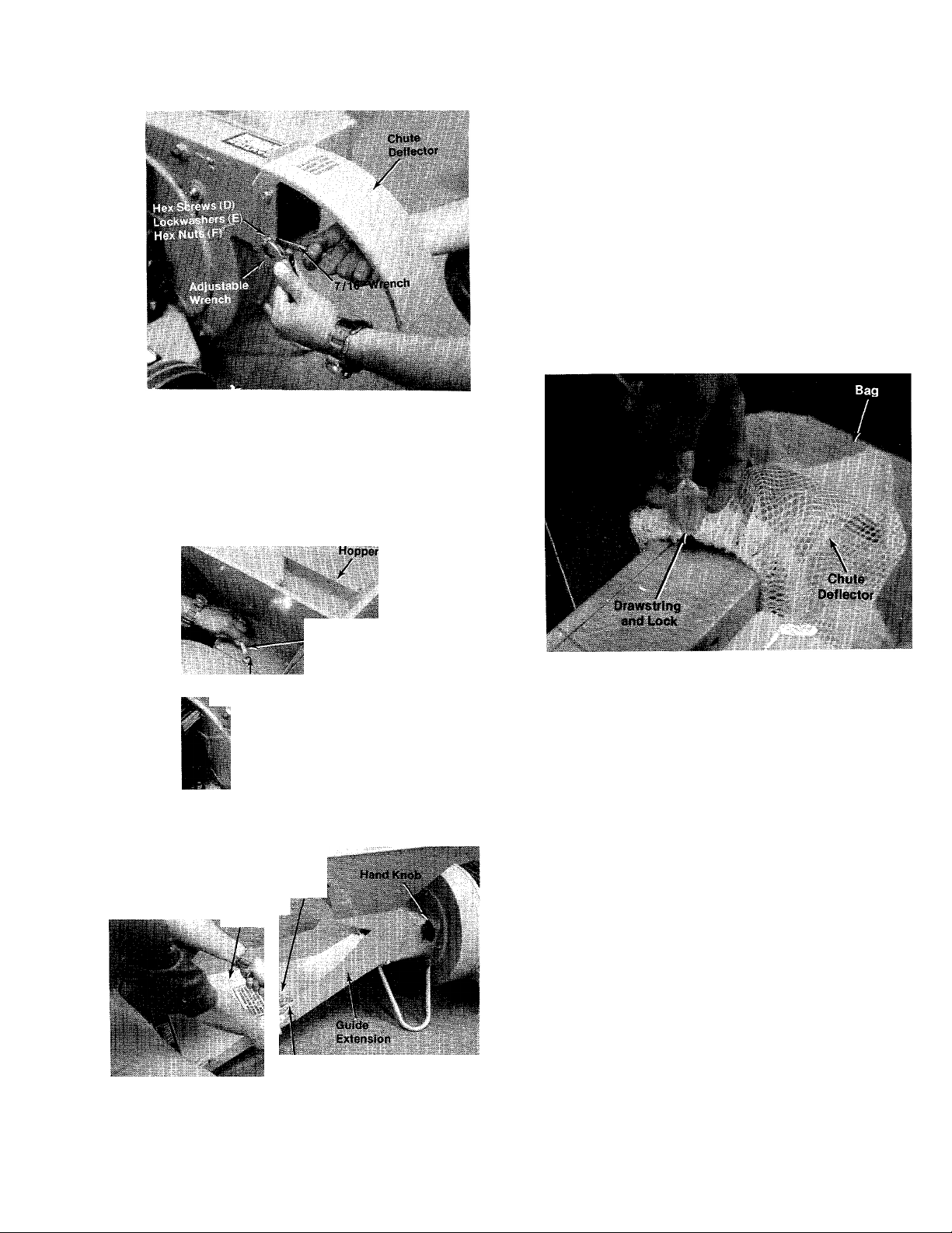
2. Chute Deflector:
A. Place the chute deflector, in position on
the left hand side of shredder.
B. Secure with four hex screws (D), lock-
washers (E) and hex center locknuts (F).
See figure 3.
NOTE
Heads of screws are assembled
from the inside, nuts and washers
go on the outside. Start all four
screws, nuts and washers by hand,
then tighten with an adjustable
wrench and 7/16” wrench.
Page 5
FIGURES.
3. Hopper:
A. Place the hopper on the shredder, start all
three self threading screws (A) by hand
and then tighten with a I/2” wrench. See
figure 4.
4. Upper Guide Extension:
A. Loosen hand knob on right hand side of
shredder. See figure 5.
B. Place upper guide extension in place on
guide extension and secure with four hex
screws (B) and hex center locknuts (C). A
7/16” wrench and adjustable wrench is
required. See figure 5.
5. Place the bag over the chute deflector and pull
draw string and lock. See figure 6.
FIGURE 4.
FIGURES.
Hex Screw (A)
Upper Guide
Extensión
/■v
Adjustabl»
Wrench
7/16" Wrench
1/2”.Wronoh
FIGURES.
OPERATION
1. Service engine with gas and oil. See engine
manual packed with shredder for complete
instructions for the care and maintenance of
engine. READ DIRECTIONS CAREFULLY.
2. When ready to start engine, place throttle
control lever in CHOKE position and start
engine in accordance with instructions in
engine manual. After engine starts, move
throttle control lever to RUN position. The
engine is stopped by placing control lever in
the STOP position.
^CAUTION
The manufacturer recommends that
the operator wear safety glasses or
some other suitable eye protection
as it is possible for chips to be
ejected out of the inlet openings
while feeding material.
A<
Page 6

USING YOUR SHREDDER
Your shredder is designed for safe, efficient,
operation. CARE, OF COURSE, MUST BE
EXERCISED THAT HANDS ARE KEPT AWAY
FROM ALL OPENINGS.
Your shredder upper guide extension is adjust
able. It may be adjusted to desired height by
loosening the hand knob as shown in figure 7.
Upper guide extension can be raised to close
opening if hopper is not installed.
FIGURE 9. RAKING LEAVES AND TWIGS INTO
UPPER GUIDE EXTENSION
CHIP-IT GUIDE
A steady flow of material provides the best
results. Bulky material, such as stalks or heavy
branches, should fed into the chip-it guide
extension. See figure 10.
FIGURE 7. UPPER GUIDE EXTENSION ADJUST
MENT
Feed the material so that it slides down upper
guide extension. See figure 8.
pper Guide
Extension
FIGURE 8. FEEDING MATERIAL INTO UPPER
GUIDE EXTENSION
Leaves and small twigs can be raked into the
upper guide extension, when the upper guide
extension is lower. See figure 9.
-4* .--.’Js"
■-f ■
I
FIGURE 10. FEEDING MATERIAL INTO CHIP-IT
GUIDE
It is possible to feed too fast and you will find it
will take some experimentingl/viih feecfingTates to
get the most out of your shredder without stalling
the engine. Rotate the material.
Under certain conditions, it may be necessary to
push the materials into the inlet guide assembly.
When this becomes necessary, use a small
diameter stick—NOT YOUR HANDS. The stick
should be of a size that will be ground up if it gets
into the impeller assembly.
The discharge chute will direct the shredded
material into a pile or a container.
Do not force or jam material into chip-it guide.
Page 7

HOPPER
Leaves and smaller branches can be fed into the
hopper. See figures 11 and 12.
FIGURE 11. FEEDING MATERIAL INTO HOPPER
, CAUTION
A
Keep clear of the chute area since
the shredded material comes out
with considerable velocity. Always
stop engine and disconnect spark
plug wire when changing bags.
MAINTENANCE
CAUTION
Always stop engine and disconnect
spark plug wire before doing any
maintenance.
Cutting Blade—The blade may easily be removed
for grinding or replacement as follows:
Remove guide extension assembly by remov
1
ing four elastic locknuts (Ref. No. 11). See
page 14.
Remove bolt (Ref. No. 38), lockwasher (Ref.
No. 37), flat washer (Ref. No. 36) holding
blade (Ref. No. 45) and blade retainer (Ref.
No. 48) to engine crankshaft. See page 14.
FIGURE 12. FEEDING MATERIAL INTO HOPPER
A CAUTION
Do Not deposit material larger than
V2” diameter in hopper. This may
cause damage to the shredding
mechanism. Any material heavier
than 1/2” should be fed into the
chip-it guide extension. (See figure
10.)
NOTE
Blade is reversible and can be as
sembled to crankshaft with either
side showing.
When sharpening blade, follow the original angle
of grind as a guide. It is extremely important that
each cutting edge receives an equal amount of
grinding to prevent an unbalanced blade. An
unbalanced blade will cause excessive vibration
when rotating at high speeds and may cause
damage to the unit. Upon reassembly, make
certain all parts are assembled properly and
tightened securely.
Flails and Fingers—The flails and fingers can be
reversed when they become dull.
LUBRICATION
WHEELS—Wheel bearings are of lifetime Forti-
flex. They require no lubrication.
ENGINE—Follow engine manual for lubrication
instructions.
NOTE
Your shredder is equipped with a ny
lon bag with drawstring lock. This
will accommodate a perforated dis
posable plastic bag.
BEFORE STARTING
NOTE
Do not mix oil with gasoline.
1. Fill fuel tank with fresh regular gasoline. (See
figuréis.)
Page 8

2. Fill crankcase with oil. (See figure 13.)
Fuel T.ink
hu
3. Rewind starter—use quick full arm stroke.
Keep firm grip on handle and return rope
slowly.
’«il- г
- Í-U* Í t-;
................
-tSliS;- «': ■■
\ álfe/ílAlK
FIGURE 13.
Position equipment so that engine is setting ievei.
Remove dip stick or oil filler plug (Figure 13). Pour
oil into oil filler tube from which dip stick was
removed and fill to FULL mark on dip stick. Do not
overfill. After initial filling follow instructions on
dip stick. Be sure dip stick is screwed into filler
opening as far as it will go when measuring oil
level.
During initial break-in period, oil level should be
watched closely. See ENGINE MAINTENANCE.
Use MS classification oil. Do not use oils marked
on I v M M or mU^^ —— -
Above 32° use SAE 30; below 32° use SAE 10W.
These recommendations must be followed for
best performance and long life.
Change oil first two (2) hours of operation and
check oil level every five (5) operating hours or
each time equipment is used.
Change oil every twenty-five (25) operating hours
or sooner if equipment is operated in extremely
dusty or dirty conditions.
FIGURE 14.
TO STOP ENGINE
1. Move control lever to STOP position. See
figuréis.
2. Remove high tension wire from spark plug to
prevent accidental starting by children while
equipment is unattended.
NOTE
Carburetors are preset at the fac
tory. DO NOT attempt to make ad
justments at this time. See carbure
tor instructions outlined under CAR
BURETOR ADJUSTMENT.
TO START ENGINE
1. Place control lever (on engine) in START
position. See figure 14.
2. Move carburetor control to CHOKE position.
See figure 14.
FIGURE 15.
ENGINE MAINTENANCE
To obtain long life and trouble-free service from
your engine, certain normal maintenance must be
performed as outlined below:
1. Change oil in crankcase after first two (2)
hours of operation. Then, follow instructions
outlined on pages.
Page 9

^CAUTION
Disconnect high tension wire at
spark plug to prevent accidental
starting of engine. Unscrew oil drain
plug located on side at bottom of
engine (figure 16).
If engine has dip stick, keep oil level at mark
indicated by adding if necessary.
3. Cleaning engine—This is an aircooled engine
which operates most efficiently when the
cooling fins are clean.
Clean cylinder fins and underside of tank or
housing thoroughly of all accumulated grass and
debris.
4. Air Cleaner. (See figure 17.)
а. Paper Type Element. Remove every 10 hours
or oftener if under dusty conditions. Tap to
remove loose dirt and/or blow from inside out
with low pressure air. Replace if torn or per
forated or when plugged to maintain proper
carburetor setting (50 hours). DO NOT WASH
IN ANY LIQUID AND DO NOT OIL.
CARBURETOR ADJUSTMENTS
Do not make unnecessary adjustment. Factory
settings are correct for most application. If
adjustments are needed, proceed as follows:
NOTE
Always tip engine towards oil drain
hole. Be sure oil drains completely.
Replace oil drain plug and refill with oil as
directed on page 5 or engine nameplate.
2. Check oil every five (5) operating hours or
each time equipment is used.
Paper Element
Element
1. Close power adjusting needle (figuréis) by
turning to right (clockwise). Close finger tight
only. Forcing will cause damage.
2. Open one turn (counterclockwise).
3. Close idle adjusting needle (figuréis) by
turning to right (clockwise). Close finger tight
only. Forcing will cause damage.
4. Open one and one-half (1V2) turns (counter
clockwise).
5. Start engine. Follow starting instructions
pages.
б. With throttle open (carburetor control at RUN
or FAST position) adjust power adjusting
needle one-eighth 0 /8) turn at a time forward
or backward until engine runs smoothly. If
engine tends to stall under load enrich
mixture slightly (counterclockwise).
7. Hold throttle lever closed or move carburetor
control to IDLE or SLOW position and adjust
idle adjusting needle until engine runs
smoothly proceeding as in step six (6) above.
FIGURE 17.
-Attaching Screw
8. Allow several seconds between each adjust
ment when performing either step six (6) or
seven (7) to allow engine to react to new
setting.
Page 10

FIGUREIS.
STORAGE
INSTRUCTIONS
In event engine is to be stored for any length of
time (30 days or more), prepare as follows;
1. Drain gasoline by tipping or by syphon hose,
then run engine until remainder is used and
tank and carburetor are empty.
CAUTION
Drain into container outdoors away
from fire or flame.
2. Drain carburetor by pressing upward on bowl
drain (figuréis).
3. Inside protection of engine for storage is per
formed by removing spark plug and pouring
one ounce of SAE 30 oil through spark plug
hole into cylinder. Crank engine, without
starting, several times to spread oil over
cylinder walls.
10
Page 11

248-650A
12
/ 7
10
Page 12

PARTS LIST FOR MODEL 248-650A
REF.
PART
NO.
1 11460
2 11472 -463
736-0264 Flat Washer 5/16” Scr.*
3
712-0429 Elastic Stopnut 5/16-18 Thd.
4
5 11481
6 710-0601
NO.
COLOR
CODE
DESCRIPTION
—463 Guide Extension Assembiy
Guide Extension
—463 Hopper Assembly
Hex Wash. Hd. Self Thd. Scr.
5/16-18 X .50” Lg.
11479 —463
8
11454 —463 Back-up Plate
9
11467
10
11 712-0429 Elastic Stopnut 5/16-18 Thd.
—463
12 09966
736-0264
13
14
11480
712-0429 Elastic Stopnut 5/16-18 Thd.
15
736-0264
16
711-0566 Chute Pivot Rod
17
712-0107 Hex Cent. L-Nut V4-20 Thd.
18
710-0289 Hex Scr. V4-20 x .50” Lg.*
19
*For faster service obtain standard nuts, boits and washers
localiy. if these items cannot be obtained locaily, order by
part number and size as shown on parts iist.
When ordering parts, if color or finish is important u^e the
appropriate color code shown above (e.g. Top Flite
Red Finish—11907(463).) /
Clamp Rod Assembly
Inlet Guide Assembly
Knob Ass’y-
FI-Wash. .50” Dia.*
Stop Washer
FI-Wash. .50” Dia.*
(463—Top FliteRed)
/
NEW
PART
The engine is not under warranty by the shredder manufacturer, if repairs or service is needed on the
engine, please contact your nearest authorized engine service outlet. Check the “Yellow Pages” of
your telephone book under “Engines—Gasoline.”
NOTE
This instruction manual covers various
models and all specifications shown do not
necessarily apply to your model. Specifica
tions subject to change without notice or
obligation.
Find It Fast
In The
Yellow Pages
13
Page 13

248-650A
J7Ü-5V/
/Ài МШийЬ.
14
Page 14

PARTS LIST FOR MODEL NO. 248-650A
PART
REF.
NO.
1
11476
2
710-0465 HexScr. 1/2-20x4.50” Lg.*
NO.
COLOR
CODE
—463
DESCRIPTION
Door—Chip-lt
3 711-0580 Clevis Pin
4 711-0579 Flail Spacer 7/32” Lg.
11455 —463
5
Cutting Finger
6 736-0921 L-Wash. 1/2” Scr.*
7 726-0111
712-0922
8
Palnut3/16” Dia.
Hex Jam Nut Va-20 Thd.*
9 714-0507 Cotter Pin 3/32” Dia. x ¥4”
Lg.*
10 11465 —463 Chute Deflector
712-0107
11
L-Nut 1/4-20 Thd.
12 710-0289 HexScr. 1/4-20 X.50” Lg.*
714-0114
13
Sq. Key 1/4” X 2.00” Lg.*
14 13430 —463 Impeller Assembly
710-0157
15
16 736-0119
171811452 —463
HexScr. 5/16-24 X 3/4” Lg.*
L-Wash.5/16” Scr.*
Hopper to Engine Mtg. Plate
Engine
11464
19
20
712-0123 Hex Nut 5/16-24Thd.*
21 736-0119
22
736-0119 L-Wash. 5/16” Scr.*
23
712-0123 Hex Nut 5/16-24Thd.*
24
726-0221
25
07006
26 08306
27 736-0100
710-0624
28
29 712-0429
30 710-0237
714-0144
31
—463 Engine Mounting Plate
L-Wash. 5/16” Scr.*
Push Cap
Fortiflex Bearing
—522 Wheel Ass’y.—Comp.
FI-Wash. ,50”I.D.*
Hex Scr. 5/16-24x1.50” Lg.*
Elastic Stopnut 5/16-18 Thd.
Hex Scr. 5/16-24 X.62” Lg.*
Cotter Pin 1/8” Dia. X 1.00”
Lg.* (Special)
736-0192
32
FI-Wash. .531”I.D. X.937
O.D. X .09
33
11459
34
71^0564
35
711-0578
36 736-0247
—463 Flail
Flail Spacer 23/32” Lg.
Clevis Pin .50” Dia. X 3.0” Lg.
FI-Wash. .406” 1. D. X 1.25”
O.D. Hdn.
37 736-0217
38
710-0151 Hex Scr. 3/8-24x2.00” Lg.
L-Wash. 3/8” Scr. H.D.
H.T.
11474
39
712-0107
40
414211477
11478
43 726-0111
44
712-0109
—463
Flail Housing Ass’y.—Comp.
Hex Cent. L-Nut 1^-20Thd.
—463 Upper Guide Extension Ass’y.
Hinge Pin
Palnut3/16” Dia.
Wing Nut Elastic 1^-20 Thd.
45 13431 —463 Blade
46 11475 —463
764-0126
Axle
Bag (Not Shown)
NEW
PART
(463—Top FliteRed)
When ordering parts, if color or finish is important use the
appropriate color code shown above (e.g. Top Flite
Red Finish—11907(463).)
The engine is not under warranty by the shredder manufacturer. If repairs or service is needed on the
engine, please contact your nearest authorized engine service outlet. Check the “Yellow Pages” of
your telephone book under “Engines—Gasoline.”
'For faster service obtain standard nuts, bolts arid washers
locally. If these items cannot be obtained locally, prder by
part number and size as shown on parts list.
15
Find It Fast
In The
Yellow Pages
Page 15

PARTS INFORMATION
POWER EQUIPMENT PARTS AND SERVICE
Parts and service for all MTD manufactured power equip
ment are available through the authorized service firm s
listed below. All orders should specify the m<yiel number
of your unit, parts number, description of parts and the
quantity of each part required.
ALABAMA BIRMINGHAM
Auto Electric & Carburetor Co
ARKANSAS NORTH LITTLE ROCK
Sutton's Lawn Mower Shop
Mity Mite Motors, Inc................. 2515 Towson Ave.............. 72901
CALIFORNIA PORTERVILLE
Billious..................................75 North D Street
Lawn Mower Supply Co
J.W. Jewett Co. .......................981 Folsom St
Luttig & Severson..................... 2030 28th St
COLORADO DENVER
South Denver Lawn Equip
CONNECTICUT SUFFIELD
The Jones & Ramsey Co
FLORIDA JACKSONVILLE
Radco Distributors
Moz-AII of Florida, Inc
GEORGIA EAST POINT
Eost Point Cycle & Key
ILLINOIS LYONS
Keen Edge Co...........................8615 Ogden Ave
INDIANA ELKHART
Parts 8 Sales Inc
IOWA DUBUQUE
Power Lawn 8 Garden Equip
LOUISIANA NEW ORLEANS
Suhren Engine Co
MARYLAND TAKOMA PARK
Center Supply Co
MASSACHUSETTS SPRINGFIELD
Morton B. Collins Co
MICHIGAN MOUNT CLEMENS
Power Equipment Dist
Lorenz Service Co
MINNESOTA MINNETONKA
Hance Distributing Inc
MISSISSIPPI BILOXI
Biloxi Sales 8 Service, Inc
MISSOURI KANSAS CITY
Automotive Equip. Service
Henzier, Inc
NEW JERSEY BELLMAWR
Lawnmower Parts Inc
....................
.......................
......................
......................
..................
....................
............................
.......
2625 4th Ave. S
...........
Rt. 4, Box 368
FORT SMITH
SAN BERNARDINO
...............
25608 E. Baseline
SAN FRANCISCO
SACRAMENTO
...........
.............
................
...............
................
................
............
................
527 West Evans................ 80223
850 Thompsonville Rd. . . . 06078
2403 Market St
CORAL GABLES
365 Greco Ave
2834 Church St
2101 Industrial Pkwy
........
2551 J.F. Kennedy
8330 Earhart Blvd
6867 New Hampshire Ave. 20012
300BirnieAve.................. 01107
36463 South Gratiot........... 48043
LANSING
2500 S. Pennsylvania .... 48900
11212 Wayzato Blvd...........55343
506 Caillavet St
..........
3117 Holmes St.................64109
ST. LOUIS
2015 Lemay Ferry Rd
717 Creek Rd., P.O. Box 7 08030
...............
................
..............
............
.................
..................
.................
................
...............
...............
..........
............
.............
...............
.........
35233
72117
93257
92410
94107
95818
32206
33146
30344
60534
46514
52001
70118
39533
63125
BRIGGS & STRATTON, TECUMSEH AND PEERLESS PARTS AND SERVICE
Briggs & Stratton, Tecumseh and Peerless parts an '
service should be handled by your nearest authorize
engine service firm. Check the yellow pages of your
telephone directory under the listing Engines—Gasoline,
Briggs & Stratton or Tecumseh Lauson.
NEW YORK CARTHAGE
Gamble Dist., Inc......................West End Ave
NORTH CAROLINA GREENSBORO
Dixie Sales Company
Smith Hardware Co....................51 5 N. George St
OHIO WADSWORTH
National Central
Bleckrie, Inc
Stebe's Mid-State Mower Supply . Box 366 ........................... 43112
Sunshine Wholesale Tire Outlet . . Route 224
OKLAHOMA MUSKOGEE
Victory Motors, Inc
Ada Auto Supply
OREGON PORTLAND
Kenton Supply Co
PENNSYLVANIA LANCASTER
Raub Supply Co
Bluemont Co............................11125 Frankstown Rd. ... 15235
TENNESSEE KNOXVILLE
Master Repair Service
Memphis Cycle 8 Supply Co
American Sales 8 Service, Inc. ... 1922 Lynnbrook
TEXAS DALLAS
Marr Brothers, Inc
Bullard Supply Co
Catto & Putty, Inc
Woodson Sales Corp
..................
GOLDSBORO
.......................
...........................
CLEVELAND
CARROLL
WILLARD
...................
........................
......................
.......................
ADA
PITTSBURGH
................
MEMPHIS
..........
.....................
......................
.....................
HOUSTON
SAN ANTONIO
FORT WORTH
...................
327 Battleground Ave. . . . 27402
687 Seville Rd
7900 Lorain Ave
605 S. Cherokee
301 E. 12th St
8216 N. Denver Ave
James 8 Mulberry Sts
2423 Broadway, N.E
421 Monroe Ave
423 E. Jefferson
2409 Commerce St
P.O. Box 2408 ..................78206
1702 N. Sylvania
..................
.............
................
...............
......................
...............
.................
...........
..........
..........
................
...................
..............
...........
..............
13619
27530
44281
44102
44890
74401
74820
97217
17604
37917
38103
3811'
7520«
77003
76111
UTAH SALT LAKE CITY
A-l Engine 8 Mower Co
VERMONT BURLINGTON
Vermont Appliance Co
...............
........... 44 Lakeside Ave
437 E. 9th St
...................
.............
84111
05401
VIRGINIA RICHMOND
RBI Corp
.................................
963 Myers St
...................
23260
WASHINGTON SEATTLE
Bailey's Rebuild, Inc
WEST VIRGINIA CHARLESTON
Young's, Inc
WISCONSIN APPLETON
Automotive Supply Co................ 1.23 S. Linwood Ave
...................
............................
1325 E. Madison St
233 Virginia St., E
............
............
.........
98102
25301
54911
WARRANTY PARTS AND SERVICE POLICY
The purpose of warranty is to protect the customer from defects in workmanship and materials, detects which are NOT detected at the time of
manufacture. It does not provide for the unlimited and unrestricted replacement of parts. Use and maintenance are the responsibility of the
customer. The manufacturer cannot assume responsibility for conditions which it has no control. Simply put, if it's the manufacturer's fault, it's
the manufacturer's responsibility; if it's the customer's fault, it's the customer's responsibility.
CLAIMS AGAINST THE MANUFACTURER S
WARRANTY INCLUDES
1. Replacement of Missing Parts on new equipment.
2. Replacement of Defective Posts within the warranty period.
3. Repair of Defects within the warranty period.
All claims MUST be substantiated with the following information:
1. Model Number of unit involved.
2. Date unit was purchased or first put into service.
3. Date of failure.
4. Nature of failure.
MTD PRODUCTS INC • 5389 WEST 130th STREET • P.O. BOX 2741 CLEVELAND OHIO 44111
 Loading...