

Page 1
VERTICAL
DUCRR
MODEL NUMBERS
PRO/20
(248-622-003)
424/LCD/20
(248-623-003) Fro as.
IMPORTANT:
•Read this Manual
Before Attempting
to Assemble and
VP UJ
LOG SPLITTERS
V9L / '
L.t
Use
Read Safety
Rules and
Instructions
Carefully
Protect Your
Warranty —
Read Separate
Log Splitter
Information
Sheet
Carefully
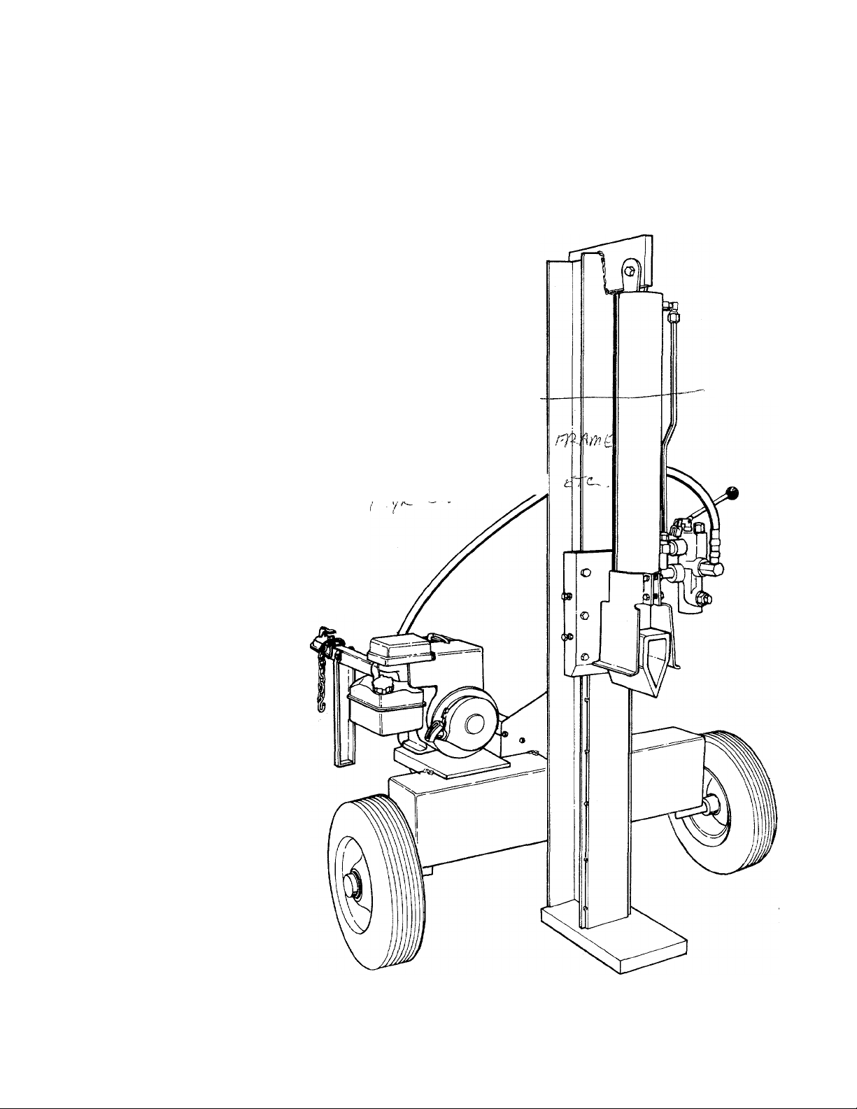
(Model PRO/20 Shown)
DUERR INC. • E. 12122 DM MOUNT ROAD • MEAD, m. 99021
(509) 238-6124 - A/o/^/V M ^ OJoAb
-y7p/l
Page 2

INDEX
Rules for Safe Operation..........................................3
Assembly Instructions............................................. . 5
Operation..................................................................9
Adjustments
Maintenance...........................................................12
.........................................................
.11
Off-Season Storage.................................................13
Trouble Shooting Chart............................................13
Illustrated Parts........................................................V
Repair Parts List......................................................1
Limited Warranty......................................Back Cover
A
WARNING
This unit is equipped with an internal combustion engine and should not be used on or near any unim
proved forest-covered, brush-covered or grass-covered land unless the engine's exhaust system is equipped
with a spark arrester meeting applicable local or state laws (if any). If a spark arrester is used, it should
be maintained in effective working order by the operator.
In the State of California the above is requi
Code). Other states may have similar lawi
the muffler is available through your nearest engine authorized service center or through DUERR INC.
Order Briggs and Stratton service part number 392390.
ed by law (Section 4442 of the California Public Resources
Federal laws apply on federal lands. A spark arrester for
2
Page 3
A
IMPOFnANT
RULES FOR SAFE OPERATION
THIS SYMBOL POINTS OUT IMPORTANT SAFETY INSTRUCTIONS WHICH, IF NOT FOLLOWED, COULD ENDANGER THE
PERSONAL SAFETY AND/OR PROPERTY OF YOURSELF AND OTHERS. READ AND FOLLOW ALL INSTRUCTIONS IN THIS MANUAL BEFORE
ATTEMPTING TO OPERATE YOUR LOG SPLITTER. FAILURE TO COMPLY WITH THESE INSTRUCTIONS MAY RESULT IN PERSONAL INJURY.
WHEN YOU SEE THIS SYMBOL
Your log splitter was built to be operated according to the rules for safe operation in this
manual. As with any type of power equipment, carelessness or error on the part of the
operator can result in serious injury. If you violate any of these rules, you may cause
serious injury to yourself or others.
- A HEED ITS WARNING.
DANGER
A
TRAINING
A
1. Before operating this splitter, read and understand this
manual completely. Become familiar with it for your own
safety To fail to do so may cause serious injury. Do not
allow anyone to operate your splitter who has not read
this manual. Keep this manual in a safe place for future
and regular reference and for ordering replacement parts.
2. Never use your splitter for any other purpose than
splitting wood. It is designed for this use and any other
use may cause an injury. Your log splitter is a precision
piece of power equipment, not a playtoy. Therefore,
exercise extreme caution at all times.
Never allow children to operate your log splitter. Do not
^ allow adults to operate it without proper instruction.
Only persons well acquainted with these rules of safe
operation should be allowed to use your log splitter.
4. Only the operator is to be near your log splitter during use.
Keep all others, including pets and children, a minimum
of 20 feet away from your work zone. Flying wood can
be hazardous. If a helper is assisting in loading logs, never
activate the control until the helper is clear of the area.
More accidents occur when more than one person
operates the log splitter than at any other time.
5. No one should operate this unit while intoxicated or while
taking medication that impairs the senses or reactions.
A clear mind is essential for safety. Never allow a
person who is tired or otherwise not alert to use your
splitter.
Never operate your splitter on slippery, wet muddy or icy
surfaces. Safe footing is essential in preventing accidents.
Never operate your splitter while attached to a towing
vehicle.
Only operate your splitter on level ground and not on the
side of a hill. It could tip, or rolling logs or poor footing
could cause an accident. Operating the splitter on level
ground also prevents the spillage of gasoline from the
fuel tank.
9.
Never attempt to move the log splitter over hilly or uneven
terrain without a tow vehicle or adequate help.
10.
Always block the wheels to prevent movement of log
splitter while in operation.
Check the fuel before starting the engine. Gasoline is an
11.
extremely flammable fuel. Do not fill the gasoline tank
indoors, when the engine is running, or while the engine
is still hot. Replace gasoline cap securely and wipe off
any splilled gasoline before starting the engine as it may
cause a fire or explosion.
12.
Both ends of each log must be cut as square as
possible to help prevent the log from riding out of the
splitter during operation.
OPERATION
A
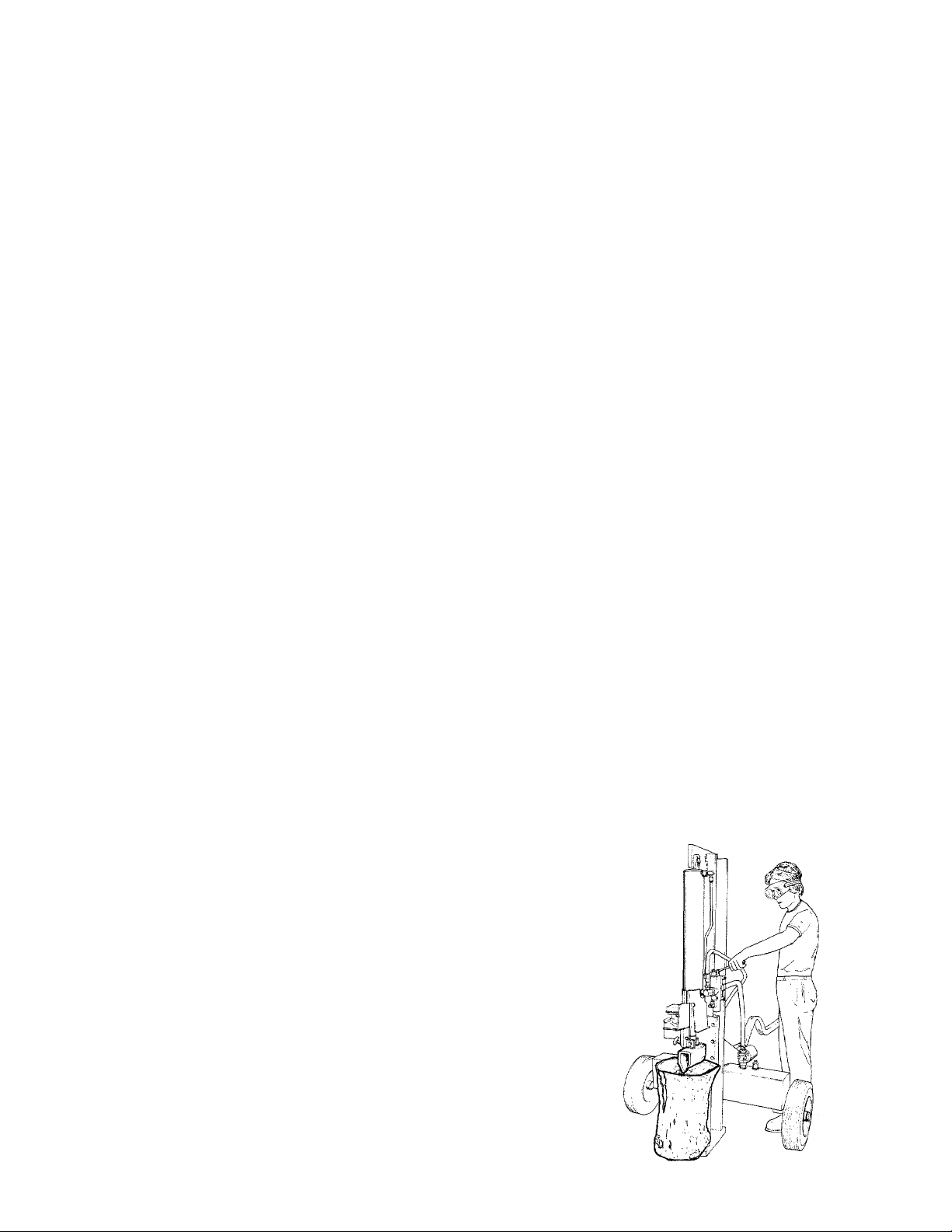
1. Stand behind the reservoir tank when operating. See
illustration.
A
PREPARATION
1. Never wear loose clothing or jewelry that can be caught by
moving parts of your log splitter and pull you into it. Keep
clothing away from all moving parts of your log splitter.
2. Wear proper head gear to keep hair away from moving
parts. Always wear protective hearing devices as needed.
3. Always wear safety shoes. A dropped log can seriously
injure your foot.
4. Always wear safety glasses or goggles while operating
your splitter. A piece of splitting log could fly off and hit
your eyes.
If you wear gloves, be sure they are tight fitting without
loose cuffs or draw strings.
6. Use your log splitter in daylight, or under good artificial
light.
Page 4

2. Know how to stop the unit and disengage the cor trols.
3. Never place hands or feet between log and splitting v /edge
or between log and end plate during forward or reverse
stroke. To do so may result in crushed or ampi fated
fingers or toes, or worse, you may lose an arm or foot.
4. Do not straddle the splitter when using it. A slip in any
position could result in a serious injury.
5. Do not step over your log splitter when the eng ne is
running. You may trip or accidentally activate the
splitting wedge if you step over. If you need to (¡et to
the other side, walk around.
6. Never try to split two logs on top of each other. Dm! may
fly out and injure you.
7. When loading the log splitter, place your hands on th s side
of the log, not at the ends. Never attempt to loac your
splitter while the splitting wedge is in motion. Yon may
get caught by the wedge and injured.
8. Only use your hand to operate the splitting weege or
control lever. Never use your foot or a rope or any other
extension device. This could result in your ability to stop
your splitter quickly enough and cause injury.
9. Always keep fingers away from any cracks that open in
the log during splitting operation. They can quickly close
and pinch or amputate your fingers.
10. Never attempt to split wood across the grain. Some types
of wood may burst or fly out of your splitter and result
in injury to you or a bystander.
11. For logs that are not cut square, the longest portion of the
log should be rotated down and the most square end
placed against the splitting wedge.
12. Keep your work area clean. Immediately removí split
wood around your splitter so that you do not stumble
over it. Clean chips
after each log is split, or whenever necessary to main
tain flat contact between wood and end plate (platlorm).
13. Never move the log splitter while the engine is running.
14. Never leave your log splitter unattended with the e ngine
running. Shut off the engine if you are ieaving your s plittei;
even for a short period of time. Someone could ac ;identally activate the splitting wedge and be injured.
15. Do not run engine in an enclosed area. Exhaust gases
contain carbon monoxide. This odorless gas cm be
deadly when inhaled.
16. Be careful not to touch the muffler after the engir e has
been running as it is HOT.
17. If the equipment should start to vibrate abnormally, stop
the engine and check immediately for the cause. Vi! ¡ration
is generally a warning of trouble.
18. When cleaning, repairing or inspecting, make certain all
moving parts have stopped. Disconnect the spark plug
wire and keep the wire away from the plug to prevent
accidental starting.
and dirt off end plate (wood pleiform)
MAINTENANCE AND STORAGE
▲
1. Do not operate your splitter in poor mechanical
condition or when in need of repair.
2. Periodically check that all nuts, bolts, screws, hose c lamps
and hydraulic fittings are tight to be sure equiprr ent is
in safe working condition. Where appropriate, chuck all
safety guards and shields to be sure they are ;n the
proper position. Never operate your splitter with safety
guards, shields or other protective features removed.
These safety devices are for your protection.
3. Replace all damaged or worn parts such as hydraulic
hoses and fittings immediately with manufacturer approv
ed replacement parts.
4. Do not change the engine governor settings or overspeed
the engine. This increases the hazard of personal injury.
The maximum engine speed is preset by the manufac-"
turer and is within safety limits.
5. Do not alter your splitter in any manner such as attaching
a rope or extension to the control lever or adding to the
width or height of the wedge. Such alterations may cause
your splitter to be unsafe.
6. Perform all recommended maintenance procedures before
you use your splitter.
7. Do not service or repair your log splitter without
disconnecting the spark plug wire.
8. Never store the equipment with gasoline in the tank
inside of a building where ignition sources are present,
such as hot water and space heaters, clothes dryers and
the like. Allow the engine to cool before storing in any
enclosure.
9. Always store gasoline in an approved, tightly sealed
container. Store the container in a cool, dry place. Do
not store in a building where ignition sources are present.
10. To reduce fire hazard, keep engine free of grass, leaves,
wood chips, and excessive grease and oil.
11. The hydraulic system of your log splitter requires careful
inspection, along with the mechanical parts. Be sure to
replace frayed, kinked, or otherwise damaged hydraulic
components.
12. Fluid escaping from a very small hole can be almost
invisible. Do not check for leaks with your hand.
Escaping fluid under pressure can have sufficient force
to penetrate skin, causing serious personal injury. Leaks
can be located by passing a piece of cardboard or wo'’'"
over the suspected leak and looking for discoloratic
13. Should it become necessary to loosen or remove any
hydraulic fitting or line, be sure to relieve all pressure
by shutting off the engine and moving the control
handle back and forth several times.
14. Do not remove the cap from the hydraulic tank or
reservoir while your log splitter is running. Hot oil under
pressure could cause injury.
15. The pressure relief valve on your splitter is preset at the
factory. Do not adjust the valve. Only a qualified service
technician should perform this adjustment.
16. Completely drain fuel tank prior to storage. This guards
against accumulation of fuel fumes which could result
in a fire hazard.
17. Never store log splitter outside without a waterproof cover.
Rain will cause rust on the inside of the cylinder
TOWING
A
1. This unit should not be towed on any street, highway or
public road without checking the existing federal, local
or state vehicle requirements. Any licensing or modifica
tions such as taillights, etc., needed to comply with the
existing federal, local or state vehicle requirements is the
sole responsibility of the purchaser.
2. Before towing, be certain the log splitter is correctly and
securely attached to the towing vehicle, and the safr ' "
chains are in place. Leave slack in chains for turnr
allowance.
3. Do not allow anyone to sit or ride on your splitter. They
can easily fall off and be seriously injured.
Page 5
IMPORTANT
ASSEMBLY
This unit has been shipped without
gasoline or oil in the engine. After
assembly, refer to separate engine
manual for proper fuel and engine oil
information.
Reservoir Tank
Assembly
Wedge and Beam Assembly
__________Jl_______
Tongue Assembly
\
Pivot
Latch
\ Hydraulic-
Assembly
Cylinder and
Valve Assembly
FIGURE 1
FIGURE 2
Hydraulic
Filter
Head
Filter
Engine and
Pump Assembly
Hoses
Wheels
Hub Cap
Stripper
Assembly
UNPACKING
Remove all parts from the carton. Make certain all
parts and literature have been removed from the
carton before the carton is discarded.
NOTE
All hardware for assembly of the log
splitter has been placed in position on
the various parts.
Other Materials Required for Assembly:
Wheel Bearing Grease
Loc-tite Hydraulic Sealer or Equivalent
Engine Oil
Unleaded Gasoline (regular grade gasoline is an
acceptable substitute)
Approximately 6-1/2 Gallons of 10 Weight AW type
fluid or Dexron 11 Automatic Transmission Fluid
Loose Parts in Carton: (See figure 1)
(1) Reservoir Tank Assembly
(2) Wheels
(1) Wedge and Beam Assembly
(1) Tongue Assembly
(1) Pivot Latch
(1) Hitch Assembly
(1) Engine and Pump Assembly
(3) Hoses (taped together)
(1) Cylinder and Valve Assembly
(1) Stripper Assembly (two halves)
(2) Fenders (Not Shown —Model 424/LCD/20)
(1) Filter Head^
(1) Hydraulic Filter*
*May be already assembled to the reservoir tank.
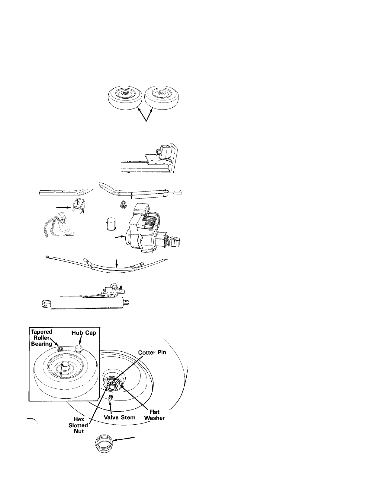
INSTALLATION OF WHEELS
Attach the wheels to the reservoir tank as follows.
See figure 2.
1. Pry off the hub caps which are attached to the
wheels. Remove one tapered roller bearing from
inside each wheel. See inset, figure 2.
2. Remove the cotter pin, hex slotted nut and one
flat washer from each axle (leave spacers and
two flat washers in place on axles).
3. Place one wheel on each axle, with the valve
stem facing outward.
4. Pack the tapered roller bearings with wheel
bearing grease, and place one on each axle.
5. Place one flat washer removed in step 2 on each
axle. Secure with hex slotted nut. Tighten
slotted nut until snug, then back off approx
imately 1/3 turn or until one of the slots on the
slotted nut lines up with the hole in the axle.
6. Check the assembly of the wheels. There should
be no side to side play, and the wheels should
spin freely.
7. Place hub caps in position on wheels and tap
on with a rubber mallet or plastic hammer.
Page 6

Fender
Lock Washer
FIGURE 3
ATTACHING THE FENDERS (Model 424/LCD/20)
1. Remove the hex nuts, lock washers, flat washers
and hex bolts from the fender support brackets.
Place the fenders in position against the fender
support brackets. Insert hex bolts through holes
in support brackets and fenders. Secure with flat
washers, lock washers and hex nuts. See figure
3. Tighten securely.
INSTALLING THE HYDRAULIC FILTER (If not already assembled)
If the hydraulic filter head and hydraulic filter have
not already been installed on the reservoir tank at
the factory, proceed as follows.
1. Place Loc-tite hydraulic sealer or equivalent on
the threads on the fitting on top of the
reservoir tank.
Thread hydraulic filter head onto fitting on top
of the reservoir tank as shown in figure 4, in
set. The direction arrow on the filter head must
point down toward the tank. Filter head must
be positioned as shown.
Oil the gasket on the top of the hydraulic filter
using automatic transmission fluid. Thread the
hydraulic filter onto the hydraulic filter head as
shown in figure 4. Tighten by hand.
Hydraulic Filter
FIGURE 4
Hex Bolts
Hex Nuts
ATTACHING THE WEDGE AND BEAM ASSEMBLY
The beam has been shipped with the wedge
down against the end plate, and tightened in this
position. Stand the beam upright, making
certain the wedge is down against the end of
the beam.
A
Do not attempt to stand beam upright
if the wedge is not against the end of
the beam, to avoid personal injury.
(Move wedge so it is against end of
beam).
Remove the pivot pin from the bracket on the
2.
beam by removing the cotter pin. See figure 4.
Roll the reservoir tank in position against the
3.
beam. Secure beam to tank using pivot pin and
cotter pin just removed.
ATTACHING TONGUE TO RESERVOIR TANK
1. The tongue is shipped with the jack stand
already attached to the tongue. The jack stand
is in the transport position. Remove the spring
pin and clevis pin. Pivot the jack stand to the
_ operating position and replace the clevis pin and
spring pin. See figure 5.
2. Remove the two hex bolts, lock washers and he.
nuts on the front of the reservoir tank. Place the
tongue in position and secure with hardware
just removed. See figure 4.
WARNING
Page 7

FIGURE 6
FIGURE 7
Hose Clamp
Hex Bolts
Lock Washers
Hex Nuts
Suction Hose
Pump
INSTALLING THE HITCH
1. Remove the two long hex bolts, lock washers
and hex nuts which are assembled through the
sides of the hitch. Do not remove the chain and
spacer from the one hex bolt.
2. Place the hitch in position on the end of the
tongue. Secure with hardware just removed. See
figure 5.
INSTALLATION OF PIVOT LATCH
1. Remove the two hex bolts, lock washers and
hex nuts on the pivot latch.
2. With the beam still in the upright position, place
the pivot latch on the beam as shown in figure
6. Secure with hex bolts, lock washers and hex
nuts just removed. The heads of the bolts must
be inside the pivot latch.
ATTACHING THE ENGINE AND PUMP ASSEMBLY
1. Remove the four hex bolts, lock washers and
hex nuts from the engine mounting bracket
(attached to the reservoir tank).
Place the engine and pump assembly in position
as shown in figure 7. Secure with hardware just
removed. Tighten securely.
ATTACHING THE SUCTION HOSE
1. The suction hose is 3/4" by 20" long. Loosen
the hose clamps on each end of the hose
using a screwdriver.
2. Attach one end of the hose to the fitting on the
bottom of the pump. Attach the other end to
the reservoir tank. See figure 7.
Place hose clamps at the base of the fittings,
3.
and tighten securely.
FIGURE 8
ADJUSTING THE SPLITTING WEDGE
The adjustment bolts on the splitting wedge were
tightened at the factory to hold the wedge in a sta
tionary position for shipping. Adjust these bolts as
■follows. See figure 8.
1. Loosen the three hex bolts on top of the slide
plate (beneath the splitting wedge).
2. Back the two adjustment bolts on the side of the
slide plate out slowly until the wedge assembly
will slide on the beam. Tighten the lock nuts
securely against the base of the slide plate to
hold the bolts in this position.
3. Retighten the three hex bolts on top of the slide
plate.
Page 8

iNSTALLING THE CYLINDER AND VALVE ASSEMBLY
1. Lower the beam to the horizontal position as
follows.
a. Remove the spring pin from the pivot latch
on the back side of the beam. Remove the
clevis pin.
— b. Lower the beam so the tongue is inside the
pivot latch. Secure with clevis pin and spring
pin.
2. Remove one hairpin clip from the clevis pin on
the end of the cylinder. Place the cylinder in
position on the log splitter, and secure with
clevis pin and hairpin clip just removed. See
figure 9.
3. Remove the large hex bolt, lock washer and hex
nut on the end of the wedge assembly. Secure
the other end of the cylinder assembly with the
hardware just removed. See figure 10.
ATTACHING THE CONTROL HANDLE
The bottom of the control handle is already attach
ed to the valve with a cotter pin. Remove the second
cotter pin which is attached to the valve only. Place
the handle in position and secure using the second
cotter pin. See figure 10.
INSTALLING THE RETURN HOSE
1. Move the beam to the operating (upright)
position by removing the spring pin and clevis
pin from the pivot latch. Place the beam upright,
and replace clevis pin and spring pin in pivot
latch for safekeeping.
2. The return hose is 3/4" by 30" long. Loosen the
hose clamps on each end of the hose using a
screwdriver.
3. Attach one end of the hose to the fitting on the
hydraulic filter head (located on top of the reser
voir tank). Attach the other end to the fitting
beneath the valve. See figure 11.
4. Make certain the hose is adjusted so it is
relaxed and in the proper position (do not allow
hose to twist). Place hose clamps at the base
of the fittings, and tighten securely.
INSTALLING THE PRESSURE HOSE
1. The pressure hose is 1/2" x 54" long. Place
Loc-tite hydraulic sealer or equivalent on the
threads on both ends of the pressure hose.
2. Thread one end of the hose into the fitting on
top of the pump. See figure 11.
3. Thread the other end of the hose into the
fitting on top of the valve. Adjust hose so it is
relaxed and in the proper position as shown in
figure 11. Do not allow hose to twist. Then
tighten securely.
8
Page 9

FIGURE 12
ATTACHING THE STRIPPER ASSEMBLY
1. Remove the four hex bolts and hex lock nuts
which are holding the two stripper halves
together.
2. Slip one stripper half over the pipe flange on the
cylinder. Place the other stripper half on the
other side of the cylinder. See figure 12.
3. Put two hex bolts through the top of the stripper
halves, and start hex nuts on the bolts. Start the
hex bolts and nuts through the bottom of the
stripper halves in the same manner.
4. Make certain the cylinder is against the stops
located on the inside of the stripper halves.
Tighten all four nuts and bolts equally.
FINAL ASSEMBLY
1. Make certain all nuts, bolts and hose clamps are
tightened securely.
2. Before operating the log splitter, make certain to
follow the "Initial Preparation" instructions in the
Operation section.
OPERATION
INITIAL PREPARATION
1. On a firm, level surface, remove the spring pin
and clevis pin from the pivot latch. Place the
beam in the vertical position. Replace clevis pin
and spring pin in pivot latch for safekeeping.
Make certain the beam is straight up and down,
against the reservoir tank.
2. Service engine with gasoline and oil as in
structed in the separate engine manual packed
with your log splitter.
3. Lubricate the beam area where beam will slide
with engine oil (DO NOT USE GREASE). Make
certain to oil both front and back of the beam
face. Pour some oil directly into the wedge
assembly.
4. Fill the reservoir tank as follows.
a. Remove reservoir vent plug. See figure 13.
Using 10 Weight AW type fluid or Dexron II
automatic transmission fluid, fill reservoir
to the top. Replace vent plug securely.
b. Disconnect the spark plug wire and ground
against the engine. Prime the pump by
pulling the recoil starter, to turn the engine
over, approximately 10 times. Reconnect the
spark plug wire.
c. Start engine. Use the control handle to extend
the wedge to the far extended position. Leave
the wedge in this position (do not retract).
d. Refill tank to within 1-1/2" to 2" from the top
^ ^ of the tank. Total capacity of system is
approximately 6-1/2 gallons.
e. Now retract the wedge. Extend and retract
the wedge fully 10 to 12 complete cycles to
remove trapped air in the system (system is
"self-bleeding").
f. Refill the reservoir to within 1-1/2" to 2" from
the top of the tank. Much of the original fluid
has been drawn into the cylinder and hoses.
Make certain to refill the reservoir, to prevent
extreme damage to the hydraulic pump.
Failure to refill the tank will void your
warranty.
NOTE
Some fluid may overflow from the
vent plug as the system builds heat
and the fluid expands and seeks its
own level.
WARNING
ik
Do not operate the log splitter without
the proper amount of transmission
fluid in the reservoir tank.
BEFORE STARTING
Before each use, check the following:
1. On a firm level surface, remove the spring pin
and clevis pin from the pivot latch. Place the
beam in the vertical position. Replace clevis pin
and spring pin in pivot latch for safekeeping.
Make certain the beam is straight up and down,
against the reservoir tank.
Page 10

Remove the vent plug and check the fluid 13vel.
2.
Fluid level should be 1-1/2" to 2" from the top
of the tank.
IMPORTANT
Reservoir tank must be full as
instructed. Low fluid level will damage
the pump and void your warranty.
3. Lubricate the beam area where beam will slide
with engine oil ( DO NOT USE GREASE), f/lake
certain to oil both front and back of the Learn
face. Pour some oil directly into the W3dge
assembly.
4. Fill gasoline tank as instructed in the sep arate
engine manual.
5. Make certain wearing surfaces of beam are
lubricated with engine oil.
TO START ENGINE
1. Place throttle control lever on the engine in -AST
position. See figure 14.
2. Place choke lever in CHOKE position.
NOTE
A warm engine may not require
choking.
Grasp starter handle and pull rope out s owly
3.
until engine reaches start of compression
cycle (rope will pull slightly harder at this point).
Let the rope rewind slowly.
Pull rope with a rapid, continuous, full arm
4.
stroke. Keep a firm grip on the starter handle.
Let the rope rewind slowly. Do not let s arter
handle snap back against starter.
Repeat preceding instructions 3 and 4 until
5.
engine fires. When engine starts, move choke
lever halfway between CHOKE and RUN.
Move throttle control lever to IDLE positic-nfor
6.
a few minutes warm-up. Gradually move c hoke
lever to RUN position as engine warms jp.
TO STOP ENGINE
1. Move throttle control lever to OFF position.
2. Disconnect spark plug wire from spark plug and
ground against the engine to prevent
accidental starting while equipment /'
unattended.
USING THE LOG SPLITTER
WARNING
A
Use the log splitter only on a level, hard surface.
Never stand next to the splitting wedge when
operating the log splitter. Always stand behind the
reservoir tank. See figure 15. Never attempt to cut
a log in half sideways. Always split the log
lengthwise.
The log splitter is designed to be used in the vertical
position only. Do not split logs with the beam
horizontal. Maximum length of log to be split is 24".
The control handle has three positions:
FORWARD (push the control handle down) —
Splitting wedge moves toward the end plate.
Control handle will return to neutral position as
soon as handle is released.
NEUTRAL (Middle positon) — Splitting wedge stops
in place.
REVERSE (Push the control handle upward) —
Splitting wedge returns. The control handle will
lock in the reverse position, and will return
neutral automatically when the reverse strc
NOTE
In order to idle smoothly, a new
engine may require 3 to 5 minutes
running above slow idle speed. Idle
speed has been adjusted to be correct
after this break-in period.
If weather is cold, run wedge up and down
7.
beam 6 to 8 times to circulate the hyd aulic
fluid, which will warm and thin the fluic.
TO OPERATE LOG SPLITTER:
1. Set throttle as maximum speed (3450-3600
RPM).
10
Page 11

2. Place the log upright, on top of end plate.
3. Press the control handle down (forward position)
until the splitting wedge just contacts the log.
Release the control handle.
STEP BEHIND THE RESERVOIR TANK (see
figure 15) and press the control handle down
until the log is split.
5. Move the control handle upward to return the
splitting wedge.
The wedge should take approximately 14 seconds
to make a complete cycle. This speed may vary
depending on throttle setting and temperature of
hydraulic fluid.
‘■NOTE
If the control handle kicks out of
reverse too soon, it can be adjusted.
Refer to Adjustment section of this
manual.
TO TRANSPORT LOG SPLITTER
1. Lower the beam to its horizontal position.
Make certain the pivot latch is latched
securely with the clevis pin and spring pin.
2. Remove the spring pin and clevis pin which
secure the jack stand. Pivot it up against the
tongue, and secure with spring pin and clevis
pin.
3. Attach the hitch to a towing vehicle, making
certain to latch securely. Attach the safety
chains to the towing vehicle.
■Adjustments
«PUTTING WEDGE
As normal wear occurs, periodically adjust the bolts
on the slide plate (beneath the splitting wedge) as
follows to eliminate the excess space between the
wedge plate and the beam. Refer to figure 8.
1. Loosen the three hex bolts on top of the slide
plate (beneath the splitting wedge).
Back the two adjustment bolts on the side of the
2.
slide plate out slowly until the wedge assembly
will slide on the beam. Tighten the lock nuts
securely against the base of the slide plate to
hold the bolts in this position.
Retighten the three hex bolts on top of the slide
3.
plate.
CARBURETOR ADJUSTMENT
A
If any adjustments are made to the
engine while the engine is running
(e.g., carburetor), keep clear of all
moving parts. Be careful of heated
surfaces and muffler.
-'"^or carburetor adjustment may required to comisate for differences in fuel, temperature, altitude
and load. Improper adjustment will cause stalling
when splitter is under load, hard starting and higher
fuel consumption.
WARNING
Refer to the separate engine manual packed with
your log splitter for carburetor adjustment
information.
REVERSE LOCKOUT ADJUSTMENT
WARNING
A
This adjustment should be made by
an authorized service dealer only.
The spring detent for the reverse lockout can be
adjusted by turning the adjustment screw shown in
figure 16. If it is not tight enough, the control han
dle will kick out of reverse too soon, before the return
stroke is completed. If it is adjusted too tight, the
control handle will not kick out of reverse, and could
cause damage to the pump, hoses, and serious
personal injury.
If adjustment is needed, an authorized service dealer
should make the adjustment using a pressure gauge
as shown in figure 16. The reverse lockout should
kick out at 1400 p.s.i.
A
When adjusting the reverse lockout,
do not overtighten the adjustment
screw to avoid damage to the log
splitter and possible serious personal
injury.
PRESSURE ADJUSTMENT
WARNING
WARNING
A
This adjustment should be made by
an authorized service deafer only.
The pressure is preset at the factory and should not
require adjustment. The pressure should be between
3000 and 3100 p.s.i. An adjustment screw is located
on the valve and should be adjusted by an authoriz
ed service dealer only, using a pressure gauge as
shown in figure 16.
Any adjustment of the pressure without instruction
from the factory will automatically void your
warranty.
11
_________
Page 12

MAINTENANCE
A
Always stop the engine and dis
connect the spark plug wire before
performing any maintenance or
adjustments.
RESERVOIR FLUID
Check the hydraulic fluid level in the log splitter
reservoir tank before each use. Fluid level should be
1-1/2" to 2" from the top of the tank.
Change the hydraulic fluid in the reservoir every 100
hours of operation. Disconnect the suction hos(j from
the bottom of the reservoir tank, and drain thu fluid
into a suitable container. Refill using only 10 V/eight
AW type fluid or Dexron II automatic transmission
fluid, as instructed in the "Initial Preparation' sec
tion of this manual, page 9. Also, make certain to
change the hydraulic filter.
Drain the fluid and flush the reservoir
tank and hoses with kerosene
whenever any repair work is perform
ed on the tank, hydraulic pump or
valve. Contaminants in the fluid will
damage the hydraulic components.
WARNING
NOTE
WARNING
A
Use extreme caution when working
with kerosene, as it is an extremely
flammable fluid.
HOSE CLAMPS
Check the hose clamps on the suction hose (attached
to bottom of the pump) for proper tightness before
each use. Check the hose clamps on the return hose„
at least once a season.
ENGINE
Change the engine oil after first 5 hours of opera
tion. Thereafter, change every 25 hours. Check
engine oil level every 5 hours, or each time the log
splitter is used. Service air cleaner every 25 hours.
Refer to separate engine manual for complete instruc
tions for care and maintenance of the engine.
FLEXIBLE PUMP COUPLER
The flexible pump coupler is a nylon "spider" insert,
located between the pump and engine shaft. The
alignment is very critical. Over a period of time, the
coupler will harden and deteriorate. To replace,
remove the engine, slide it back and replace the
coupler. Do not loosen or remove pump. Replace
engine, leaving engine mounting bolts loose. Align
coupler, then tighten engine bolts. Make certain
coupler is tight.
For a replacement flexible pump coupler, order pp'-'“
number 717-0891.
TIRE PRESSURE
Check sidewall of tire for manufacturer's recommend
ed maximum tire pressure. If this information does
not appear on your tire, maximum tire pressure under
any circumstances is 30 p.s.i. Equal pressure should
be maintained on both tires.
HYDRAULIC FILTER
Change the hydraulic filter every 50 hours of c peration. Use only a 10 micron hydraulic filter. Order part
number 723-0405.
BEAM AND SPLITTING WEDGE
Lubricate both sides of the beam where it contacts
the splitting wedge with engine oil before each use
to obtain years of service. However, normal we jr will
occur. The wedge plate on the log splitter is design
ed so the gibs on the side of the wedge plats can
be easily removed and rotated and/or turned over for
even wear. Make certain to readjust the adjusi ment
bolts so wedge moves freely, but no excess space
exists between the wedge plate and beam.
INSTALLATION OF TIRE TO RIM
A
The following procedure must be
followed when removing or installing
a tire to the rim.
1.
Be certain rim is clean and free of rust.
2.
Lubricate both the tire and rim generously.
Never inflate to over 30 p.s.i. to seat beao„.
3.
Excessive pressure when seating beads may
cause tire/rim assembly to burst with force
sufficient to cause serious injury.
12
WARNING
Page 13

OFF-SEASON STORAGE
If the machine is to be inoperative for a period longer
than 30 days, prepare for storage as folllows.
Clean the engine and the entire unit thoroughly.
Wipe the entire machine with an oiled rag to
protect the surfaces.
Refer to the engine manual for correct engine
3.
storage instructions. The engine must be
completely drained of fuel to prevent gum
deposits from forming on essential carburetor
parts and fuel tank.
The tongue can be removed and reattached in
4.
an upright position as shown in figure 17 to take
less space when storing.
Store unit in a clean, dry area.
5.
NOTE
When storing any type of power
equipment in an unventilated or metal
storage shed, care should be taken to
rustproof the equipment. Using a light
oil or silicone, coat the equipment,
especially all moving parts.
SYMPTOM POSSIBLE CAUSE(S) SOLUTION
1. Engine fails to start
2. Hard starting or loss of
power
3. Engine overheats
4. Will not split logs
5. Leaking cylinder
TROUBLE SHOOTING CHART
A. Check fuel tank for gas.
B. Spark plug lead wire
disconnected.
C. Faulty spark plug.
A. Spark plug wire loose.
B. Dirty air cleaner. B. Clean air cleaner as described in
A. Carburetor not adjusted
properly.
B. Air flow restricted.
C. Engine oil level low.
A. Reservoir fluid level low.
B. Pump setting incorrect.
A. Broken seals.
B. Scored cylinder.
A. Fill tank if empty.
B. Connect lead wire.
C. Clean, adjust gap or replace.
A. Connect and tighten spark plug wire.
engine manual.
A. Adjust carburetor. See engine
manual.
B. Remove blower housing and clean as
described in the engine manual.
C. Fill crankcase with the proper oil.
A. Check and fill reservoir tank as
instructed in Operation Section.
B. Adjust pump setting to between
3,000 and 3,100 p.s.i.*
A. Replace seals.*
B. Replace cylinder.*
NOTE: For repairs beyond minor adjustments, please contact your local service dealer.
•Should be performed by an authorized service dealer only.
13
Page 14

PRO/20 (Model 622)7 C
PRO/22 (Model 623) $
o rAj fO (JOT p£)iRo(jJ3:
5onrt£ -TAms
NOTE: The engine is not under warranty by the log
splitter manufacturer ... If repairs or service is
needed on the engine, please contact your nearest
authorized engine service outlet. Check the "Yellow
pages" of your telephone book under " Engines —
Gasoline".
Find It Fa 3t
In The
Yellow Ps ges
14
NOTE
Specifications subject to change without notice or
obligation.
Page 15

PRO/20 (Model 622) PRO/22 (Model 623)
PARTS LIST FOR MODELS 622 and 623 LOG SPLITTERS
PART
EF.
NO.
1
NO.
710-1010
2 710-1018
710-3029
3
712-0240
4
712-0333
5
714-0470
6
736-0921
7
738-0736
8
781-0127
9
781-0129
10
781-0130
11
781-0132
12
781-0140
13
781-0142
14
710-0672
15
711-3104
16
712-3057
17
V,2
736-0119
781-0273
23
781-0148
24
710-0409
25
712-0123
26
736-0119
27
737-0236
28
717-0885
29
717-0886
30
727-0307
31
737-0235
32
737-0238
33
737-0192
34
710-0117
35
710-0237
36
710-0363
37
710-0968
712-0123
38
714-0122
39
717-0887
40
717-0891
41
719-0278
42
719-0281
COLOR
CODE
DESCRIPTION
NEW
PART
Hex Bolt 1/2-20 x 3" Lg.
(Grade 8)
N
Hex Bolt 1/2-20 x 2.75"
Lg. (Grade 8)
N
Hex Bolt 7/16-20 x 1.25"
Lg.
N 48
Hex Jam Nut 7/16-20 Thd.
Hex Nut 1/2-20 Thd.
(Grade 8)
N
Cotter Pin 1/8 Dia.
L-Wash. 1/2" I.D.*
Hinge Pin 1/2" Dia.
Fixed Side Gib
Adjustable Gib
Adjustable Gib Shim
Beam (Kss'y. AiSE /Si-013!
Wedge Ass'y.
Wedge Back Plate
N
N
N
N
N
N
N
Hex Bolt 5/16-24 x 1.25"
Lg.*
Clevis Pin
Hex Nut 5/16-24 Thd.
(Grade 5)
L-Wash. 5/16" I.D.*
Pivot Latch Brkt.
N
Engine
Tank Ass'y. Complete
N
Hex Bolt 5/16-24 x 1.75"
Lg.*
Hex Nut 5/16-24 Thd.*
L.-Wash. 5/16" I.D.*
Vent Plug
Hydraulic Cylinder**
Control Valve-
Metal Pressure Tube
3/4" Hose Barb
Pipe Nipple
Elbow
Hex Bolt 5/16-24 x 1.0"
Lg.*
Hex Bolt 5/16-24 x .62"
Lg.*
Hex Bolt 5/16-24 x 4" Lg.
(622)
Hex Bolt 5/16-24 x 5" Lg.
(623)
Hex Nut 5/16-24 Thd.*
Sq. Key 3/16" x .75"
Pump J-ET SOPl. ¿a/i£AJ XO. wHG
Flexible Coupling
Coupling Shield (622)
Coupling Shield (623)
PART
REF.
NO
43
44 727-0308
45 727-0310
46
47
NO.
COLOR
CODE
DESCRIPTION
726-0146 Adjustable Hose Clamp
Suction Hose -20"
Pressure Hose
736-0119
L-Wash. 5/16" I.D.*
737-0234 90° Swivel N
781-0097
Rear Coupling Support
Brkt.
49
781-0098
Front Coupling Support
Brkt.
50
712-0299
Hex Slotted Nut 3/4-16
Thd.
51
714-0162
Cotter Pin 5/32" Dia.
52 734-0873 Hub Cap
53
734-1016
Wheel Ass'y. Comp.
734-0872 Tire Only
734-1017 Rim Only
734-0255
54 741-0107
736-0351 Fl.-Wash. .76" I.D. x 1.5"
56
Air Valve
Roller Bearing A. PEft. IdHREl
O.D.
750-0442 Spacer 1.56" Lg.
57
723-0405 Filter Element N
58
723-0406
59
60 727-0309
710-3144 Hex Bolt 3/8-16 X 2"
61
Filter Head N
Return Hose — 30" N
Lg. (Grade 5)
62 712-0430 Hex L-Nut 3/8-16 Thd.
63 781-0168
Stripper Half » N
64 710-0521 Hex Bolt 3/8-16x 3" Lg.
(Grade 8)
710-3130 Hex Bolt 3/8-16 X 3.25"
66
N
67 711-0813 Clevis Pin 5/16" Dia.
N
712-0375 Hex L-Nut 3/8-16 Thd.
69
N
70 712-0798 Hex Nut 3/8-16 Thd.*
N
71 713-0338
N
72 732-0194 Spring Pin
N
73 727-0311
74 736-0169
736-0185
75
Lg. (Grade 8)
Tow Hitch Chain
Hitch Coupler
L-Wash. 3/8" I.D.*
Fl.-Wash. .406" I.D. x .75"
O.D.
781-0160
80
781-0162 Jack Stand
81
750-0507 Spacer 3/8" I.D. x .27" Lg.
82
710-0157
83
Tongue
Hex Bolt 5/16-24 x 3/4"
Lg, (Grade 5) t
84 781-0271
-
85
781-0272 Fender Support t
Fender t N
86 736-3014 Fl.-Wash. .78" I.D. x 2.0"
N
87
736-0159 Fl.-Wash. .344" I.D. x .88"
O.D.
O.D.
NEW
PART
N
N
•
N
N
N
N
N
N
For faster service order standard nuts, bolts, and washers locally. If these items cannot be obtained locally, order by part
number and size as shown on parts list.
**Hydraulic cylinder "0" ring kit available - order part number 753-0458. h i
t PRO/22 (Model 623) Only.^ lil-OX/D ¿} U. ^TAhlt J
15
Page 16

R WARRANTY
NON-COMMERCIAL
Limitechtp Models P,10/20 and 424/LCD/20 Log Splitters
For three years from the date of original retail purch|3%«MiERR INC will either
repair or replace, at its option, fiee of charge, F.Ojg?^f^X£M*^r authorized service
firm, any part or parts fbund to be defedd^ in'material or workmanship.
Transportation charges forNthe movemem of any power equipment unit or
attacnment are tne responsiDJi ty or me
any parts submitted for replace tmem ur
purchaser unless such return iVmques
/ \
nurcnaser. iransnnrTaTinn
PART NUMBER
7/<2 07f/
12L-QIC=9
7/0-053J0
criRrp&a.
QUAN. t
^ '
the
to
or
;he
m-
on
-rVE OPiC>a}AL 5PM£R^ M£ Ab
i^LDEla- aU THe. (jQd
rHE2L. Amts (Uil Also Used oaJ
fkirr^ 4/?£ Fa^ Op J
7K/-0/3I 2eA«i Ussi. \
7/V- OHIO /
70K-D73L
' W- 0373
72/^OJ7S
72/-0377
\
DENI^IS^UERR
PRESIOmW^^
or
/ r
ite
/
ior
/ ^
/ .
1
ich
FORM NO. 770-6254C (R870909)
'We stand behind our products'
DUERR INC. • MEAD, WASHINGTON 99021
(509) 238-6124
 Loading...