

Page 1

TEN CENTS
r
¡MANUAL
ASSEMBLY
OPERATION
MAINTENANCE
PARTS LIST
Important:
Read Safety Rules and
Instructions Carefully
Model Nos.
247-670A
247-680A
247-670-300
247-680-300
POWER
VACUUMS
PRINTED IN U.S.A.
FORM NO. 770-6786
Page 2

I M P O R T A N T
It is suggested that this manual be read in its entirety before attempting to assemble or operate. Keep this
manual in a safe place for future reference and for ordering replacement parts.
This unit is shipped WITHOUT GASOLINE or OIL. After assembly, see operating section of this manual for
proper fuel and amount.
SAFE OPERATION PRACTICES FOR POWER VACUUMS
1. Read the operating and service instructing manual
carefully. Be thoroughly familiar v/ith the controls
and proper use of the povs^er vacuum.
2. Never allow children to operate this power vac
uum.
3. Keep the area of operation clear ot all persons,
particularly small children and pets.
4. Check fuel before starting engine. Do not fill fuel
tank indoors, when engine is running, or while
engine is hot. Wipe off any spilled fuel before
starting engine.
5. Do not change engine governor settings.
6. Do not put hands near rotating parts for any rea
son.
7. If the power vacuum should start to vibrate ab
normally, stop the engine and check immediately
for the cause. Vibration is generally a warning of
trouble.
8. Before cleaning, repairing or inspecting make cer
tain all moving parts have come to a complete
stop. Disconnect spark plug wire and keep wire
away from plug to prevent accidental starting.
Also keep throttle control lever in the stop posi
tion.
9. If the power vacuum should become blocked with
debris at any point shut engine off and wait until
the impeller comes to a complete stop before at
tempting to remove the obstruction. Disconnect
spark plug wire to prevent accidental starting.
10. Check ail bolts for tightness at frequent periods.
11. Never store this power vacuum with fuel in the
tank. Allow engine to cool before starting in any
enclosure.
12. Keep bag and equipment free of debris when not
13. Never operate this power vacuum unless air duct
and vacuum bag are properly affixed in their
place. Large zippered end of bag must be closed
when operating to prevent objects from being
blown out.
14. Never empty vacuum bag when engine is running.
15. Never change inlet nozzle or auxiliary hose attach
ment when engine is running.
16. The manufacturer recommends that the operator
wear safety glasses or some other suitable eye
protection when operating this machine.
17. Check the vacuum bag frequently for wear and
replace when necessary.
Page 3

ASSEMBLY
INSTRUCTIONS
(Refer to figures 1, 2 and 3)
1. Place the upper handle in position and fasten with
four (4) hex screws and hex centerlock nuts pro
vided.
2. Place the air duct liner in the elbow of the air
duct and fasten in position as you assemble the
air duct in step 3. (See figure 1.)
16. Engage and disengage control lever, check for
free pivoting action. It may be necessary to read
just the control rod.
OPERATION
1. Service engine with gas and oil. See engine man
ual packed with lawn mower for complete instruc
tions for care and maintenance of engine. READ
DIRECTIONS CAREFULLY.
3. Place the air duct in position on the blower hous
ing and fasten with four (4) flat washers and hex
nuts provided.
4. Slide the vacuum bag over the back of the upper
handle and snap the four flaps to hold the bag.
5. Fasten the deflector on the top of the air duct with
three hex screws, flat washers and hex nuts. (See
figure 1.)
6. Slide the bag over the air duct.
7. Fasten the nozzle to the front of the vacuum with
four flat washers and thumb nuts provided.
8. Use the following steps on the self propelled unit
only.
9. Fasten the throttle control to the right hand side
of the upper handle with one hex screw and hex
center locknut provided.
10. Secure throttle control cable to the lower handle
with the cable clip provided.
NOTE
START ENGINE
After the engine has been properly fueled and oiled
(refer to engine operating and maintenance instruc
tions), start engine in the following manner.
PUSH MODEL
1. Move throttle control lever on engine to START po
sition.
2. Crank engine. Pull recoil with a quick firm pull.
Do not pull out so far that rope stops with a jerk as
this will cause rope failure. Do not allow rope and
handle to snap back into place.
3. After two or three full firm pulls on recoil (or as
soon as engine fires), move speed control to run
position.
4. Operate a new engine at intermediate speeds and
light load for the first few hours as you would a
new automotive engine.
5. To stop engine, move speed control lever on en
gine to STOP position.
Cable clip must be assembled to lower
handle with the open end towards the
engine. This will prevent wear to the
bag.
11. Place ferrule through control lever.
12. Place flat washer over ferrule and thread control
rod into ferrule about eight or nine turns.
13. Hook formed end of control rod in the shifting
finger.
14. Place curved face of spacer towards the outside
of upper handle left hand side.
15. Fasten control lever in position with hex screw and
two hex nuts provided.
6. If carburetor needs adjustment to start or for oper
ation, see "Carburetor Readjustment" section.
SELF PROPELLED MODEL
1. Place drive engagement lever in the neutral posi
tion (towards the operator).
2. Move throttle control lever on handle to START
position.
3. Crank engine. Pull recoil with a quick firm pull.
Do not pull out so far that rope stops with a jerk
as this will cause rope failure. Do not allow rope
and handle to snap back into place.
Page 4
247-670A
247-680A
IF YOU WRITE TO US ABOUT THIS A^TICIE
OR IF YOU ORDER REPLACEMENT PARTS AL
WAYS MENTION THIS MODEL & SERIAL NO
MODEL
hand side. This should be open
when the bag becomes half full.
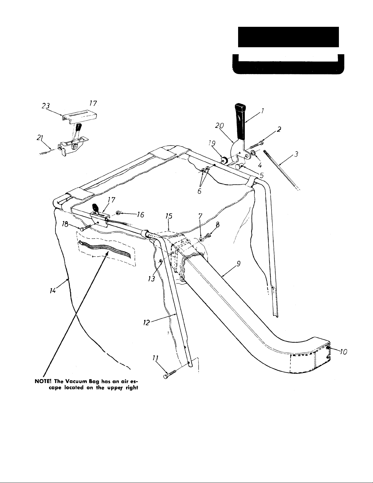
EXPLODED VIEW OF UPPER HANDLE
Page 5

PARTS LIST FOR MODELS 247-670A AND 247-680A
REF.
NO.
PART
NO.
1 720-0142
710-0606
2
COLOR
CODE
DESCRIPTION
Grip (680A)
HexScr. 1/4-20x1.50” Lg.*
(680A)
711-0596
3
4 736-0108
Control Rod (680A)
FI. Wash. .510” I.D. x .75”
O.D. (246-680A)
711-0179
5
712-0107
6
Adj. Ferrule (680A)
Hex Center L-Nut V4-20 Thd.
(680A)
7 736-0173 Flat Wash. .28” I.D. x .75”
O.D. X .063
8
9
10
11
12
13
14
15
16
17
710-0289
731-0212
12262
710-0106
12234
712-0107
764-0127
12104
712-0107
11609
HexScr. 1/4-20 X .50” Lg.*
Air Duct
Air Duct Liner
HexScr. 1/4-20x1.25” Lg.*
Upper Handle
Hex Center L-Nut V4-20 Thd.
Vacuum Bag
Deflector
Hex Center L-Nut V4-20 Thd.
Throttle Control Assy.—
Comp. (680A)
710-0606
18
748-0210
19
12226
20
21 746-0229
731-0344
23
Hex Scr. 1/4-20 x 1.50” Lq.*
Spacer (680A)
Control Lever (680A)
Conduit and Wire (680A Only)
Plastic Label (680A)
NEW
PART
NOTE: This instruction manual covers various
models and all accessories shown do not neces
sarily apply to your model vacuum.
(463—Top Flite Red)
When ordering parts, if color or finish is important use
the appropriate color code shown above (e.g. Top Flite
Red Finish—12236 (463).)
*For fastdt service obtain standard nuts, bolts, and washers locally. If these items cannot be obtained lo
cally, order by part number and size as shown on parts list.
The engine is NOT under warranty by the vacuum
manufacturer.
If repairs or service is needed
on the engine, please contact
your nearest authorized en
gine service outlet. Check the
"Yellow Pages" of your tele
phone book under "Engines
—Gasoline."
FiMlMfattiiitht
Page 6

247-670A
247-680A
NOTE;
Cable clip must be assembled
to lower handle as shown, with
open end towards the engine.
Page 7

REF.
NO.
PART
COLOR
NO.
1 710-0258
736-0329
2
712-0116
3
736-0117
4
714-0127
5
754-0176
6
7 710-0938
711-0590
8
756-0194
9
10 12206
11
732-0157
12 712-0429
13 738-0140
14
711-0596
15 12231
16 712-0429
17
12213 —463
18 732-0237
19 714-0474
20 736-0300
21 714-0137
22
12216
23 711-0594
24
720-0132
25 12208
26 732-0231
27
712-0107
28 12240 —463
29
748-0161
30 748-0164
31
736-0116
32
716-0115
33 756-0195
34
736-0160
35 748-0742
36 710-0136
37 12241 —463
38 714-0115
39 736-0116
12217 —463
40
41
734-0225
42
748-0176
43 736-0116
44
714-0115
45 712-0107
46 736-0329
47 12227 —463
48 710-0118
CODE
PARTS LIST FOR MODELS 247-670A AND 247-680A
PART
DESCRIPTION
HexScr. 1/4-20 X.62” Lg.*
(680A)
NEW
PART
REF.
NO.
49
NO.
736-0119
50 12211
Spring L-Wash. Va” Scr.*
(680A)
Hex Ins. L-Nut 3/8-24 Thd.
51 736-0119
52 710-0118
(680A)
Fl.-Wash. (680A)
Cotter Pin 1/16” Dia. X.75”
(680A)
736-0329
53
54 12222 —463
712-0267 Hex Nut 5/16-18 Thd. *
55
“V”-Belt 1/4” X 22.76” Lg.
(680A)
Set Scr 1/4-28 X .25” Lg.
56
57
736-0119
710-0258
(680A)
P.T.O. Sheave (680A)
Idler Pulley (680A)
Idler Brkt. Ass’v. (680A)
58 710-0148
717-0325
59
Spring .38”O.D. (680A)
Hex Ins. L-Nut5/16-18Thd.
(680A)
Shoulder Bolt .437” Dia. x
.180 (680A)
Control Rod (680A)
Shifting Finger (680A)
Hex Ins. L-Nut5/16-18Thd.
(680A)
Pivot Brkt. Ass’y- (680A)
Compression Spring (680A)
Cotter Pin 1 /8” Dia. x .75”
Lg.*(680A)
Fl.-Wash. (680A)
Hi-Pro-Key 3/16” X 3/4” Dia.
X1.062” Lg. (680A)
Shifting Yoke Ass’y- (680A)
Shifting Fork Rod (680A)
Grip
Index Handle Ass’y.
Torsion Spring
Hex Center L-Nut V4-20 Thd.
Pivot Brkt. Ass’y.—R.H.
Clutch Collar(680A)
Sprocket 10 Teeth (680A)
Fl.-Wash. (680A)
Snap Ring for .625” Dia.
(680A)
Drive Pulley (680A)
Fl.-Wash. (680A)
Flange Bearing (680A)
HexScr. 1/4-20x1.75” Lg.*
Pivot Brkt. Ass’y.—L.H.
Cotter Pin 1 /8” Dia. x 1.00”
Lg.*
Fl.-Wash.
Front Axle Ass’y.
Front Wheel Ass’y.—Comp.
Flange Bearing .630” I.D.
Fl.-Wash.
Cotter Pin 1/8” Dia. X 1.00”
Lg.*
Hex Center L-Nut V4-20 Thd.
(680A)
L-Wash. 1/4” Scr.* (680A)
Bearing Support Brkt. (680A
Hex Scr. 5/16-18 X.75” Lg.
(680A)
_______________
60 714-0126
713-0118
61
62 713-0723
710-0118
63
64 736-0119 L-Wash. 5/16” Scr.*
712-0267
65
66 736-0119
676812224
12200 —463
748-0227 Hex Flange Bearing .630” I.D
69
70 736-0116
71 710-0258 HexScr. 1/4-20 X.62” Lg.*
72 736-0211
73 734-0576
75 710-0118 HexScr. 5/16-18X.75” Lg.*
76 736-0119 L-Wash. 5/16” Scr.*
712-0287
77
736-0329 L-Wash. 1/4” Scr.* (680A)
78
79
710-0258
808112232
712-0107
82
746-0128
83 738-0185 Rear Axle(670A)
717-0284
84
12233
712-0107
85
714-0229 #2 Woodruff Key 3/32 x Va”
86
87 748-0136
88 711-0593
89 715-0246 Spring Pin Spirol 3/16” Dia. >
90 748-0135
919208187
748-0110
939408189
748-0108
710-0442
95
COLOR
CODE
DESCRIPTION
L-Wash. 5/16” Scr.* (680A)
—463 Gear Box Mtg. Brkt. Ass’y.
(680A)
L-Wash. 5/16” Scr.*(680A)
Hex Scr. 5/16-18 X.75” Lg.*
(680A)
L-Wash. V4”Scr.*(680A)
Gear Box Brace (680A)
(680A)
L-Wash. 5/16” Scr. (680A)
Hex Scr. V4-20X.62” Lg.*
(680A)
Hex Wash. Hd. F-TappScr. #
-32x .38” Lg. (680A)
Gear Box Ass’y.—Comp.
(680A)
#9 Hi-Pro-Key 3/16” X W’ Die i.
(680A)
Chain #41 x61 Links (680A)
#41 Master Link I/2” Pitch
Type II (680A)
Hex Scr. 5/16-18 X.75” Lg.*
Hex Nut 5/16-18Thd.*
L-Wash. 5/16” Scr.*
Index Plate Ass’y.
Engine Mtg. Frame Ass’y.
Fl.-Wash.
Fl.-Wash.
Rear Wheel Ass’y.—Comp.
Hex Nut V4-20Thd.* (680A)
HexScr. 1/4-20 X.62” Lg.*
(680A)
Chain Guard (680A)
Hex Center L-Nut V4-20 Thd.
Cable Clip
Differential Ass’y.—Comp.
(680A)
Lower Handle
Hex Center L-Nut V4-20 Thd.
Dia. Hdn. (680A)
Pinion Gear .50” I.D. x14
Teeth (680A)
Drive Shaft (680A)
1.25(680A)
Bevel Gear .62” I.D. 28 Teeth
(680A)
Gear Box Cover (680A)
Flange Bearing .630” I.D.
(680A)
Gear Box (680A)
Flange Bearing .503” I.D.
(680A)
Hex Scr. 5/16-18 x1.50 Lg.*
NEW
PART
3
'
Page 8

247-670A
247-680A
EXPLODED VIEW OF DRIVE ASSEMBLY
Page 9

PARTS LIST FOR MODELS 247-670A AND 247-680A
NO.
—
COLOR
CODE
DESCRIPTION
Hex Scr. 1/4-20x1.25” Lg.*
Part of Engine
Woodruff Key (680A)
Sq. Key V4”x2.00” Lg.
Hex Nut 5/16-18” Thd.*
L-Wash.5/16” Scr.*
Hopper to Engine Mtg. Plate
Gasket Strip—Pressure Sen.
Vane Plate Ass’yAir Vane
Blower Housing Ass’yNozzle
FI.-Wash. .344” I.D. x .88”
REF.
NO.
1
2
3
4
5
6
7
8
9
10
11
12
13
PART
710-0106
714-0108
714-0114
712-0267
736-0119
11452 -463
721-0128
12203 -463
12230 -463
12236 -463
731-0211
736-0159
O.D. X .063
14
15
712-0254
710-0239
Thumb Nut 5/16-18 Thd.
Hex Scr. 3/8-24x1.75” Lg.
H.T.
16 736-0217 L-Wash. 3/8” Scr. Heavy Duty
17 712-0107
18
736-0211
Hex Center L-Nut V4-20 Thd.
FI.-Wash. .285” I.D. x 1.25”
O.D. X.060
19 721-0129
712-0241 Hex Nut 3/8-24” Thd.*
20
736-0217 L-Wash. 3/8” Scr. Heavy Duty
21
22 710-0118
Dust Pad—Pressure Sensitive
Hex Scr. 5/16-18 x.75” Lg.*
23 736-0119 L-Wash. 5/16” Scr.*
24 736-0119 L-Wash. 5/16” Scr.*
25 710-0409
26
711-0591
27 736-0119
712-0267
28
29
30
—
12228
Hex Scr. 5/16-24x1.75” Lg.*
Engine Spacer
L-Wash. 5/16” Scr.*
Hex Nut 5/16-18 Thd.*
Engine
Handle Brace
NEW
PART
NOTE: This Instruction manual covers various
(463—Top Flite Red)
When ordering parts, if color or finish is important use
the appropriate color code shown above (e.g. Top Flite
Red Finish—12236 (463).)
*For faster service obtain standard nuts, bolts, and washers locally. If these items cannot be obtained lo
cally, order by part number and size as shown on parts list.
models and all accessories shown do not neces
sarily apply to your model vacuum.
The engine is NOT under warranty by the vacuum
manufacturer.
If repairs or service is needed
on the engine, please contact
your nearest authorized en
gine service outlet. Check the
"Yellow Pages" of your tele
phone book under "Engines
—Gasoline."
FMaalMtialM
Page 10

247-680A
(ONLY)
SHORT SHAFT
Lubricate with 2 oz. High
Temp. Grease 450°F. Order
Part No. 737-0120.
FIGURE 4.
MODEL 717-0341 DIFFERENTIAL ASSEMBLY
PARTS LIST FOR FIGURE 4 MODEL 247-680A
Ref.
No.
10 711-0276 1
11
12
13 738-0217 1
■For faster service obtain standard nuts, boits and washers locaily. If these items cannot be obtained locally, order by part
number and size as shown on parts list.
Part
No.
1
715-0247 2
2
748-0185
3
738-0218 1
4
736-0188 2
5
717-0341 2 Housing Half
6 736-0119 2
7
710-0526
8 736-0187 2
9
748-0158
712-0237 2
09054
Qty.
Req’d.
Spring Pin Spir. 3/16” Dia. X
2
Gear—Double “D” Hole
Shaft—Long 15.38” Lg.
FI-Wash. .760I.D. X 1.49 0.D.
L-Wash.5/16” Scr.*
2
Hex Scr. 5/16-24 X 4.00” Lg.*
FI-Wash. .640 I.D. x 1.24 O.D.
2
Gear—Round Hole
Drive Pin
Hex Cent. L-Nut 5/16-24 Thd.
1
Sprocket—40 Tooth
Shaft—Short 8.31 ” Lg.
Description
1.00” Lg.
10
New
Part
Page 11

Page 12

PARTS INFORMATION
POWER EQUIPMENT PARTS AND SERVICE
Ports and service for all MTD manufactured power
equipment are available through the authorized service
firms listed below. Ail orders should specify the model
number of your unit, parts numbers, description of parts
and the quantity of each part required.
ALABAMA BIRMINGHAM
Auto E loctric & Carburetor Co...2625 4fh Ave. S
ARKANSAS NORTH LITTLE ROCK
Sutton's Lown Mower Shop ___
Mity Mite Motors, Inc;
CALIFORNIA SAN BERNARDINO
Lawn Mower Supply Co.............. 25608 E. Baseline — 92410
J.W. Jewett Co
Luttig & Severson ...................... 2030 28th St
COLORADO DENVER
South Denver Lawn Equip
CONNECTICUT SUFFIELO
The Jones & Ramsey Co
FLORIDA JACKSONVILLE
Rodeo Distributors
Moz-AII of Florida, Inc
GEORGIA EAST POINT
East Point Cycle 8< Key
ILLINOIS LYONS
Keen Edge Co
INDIANA ELKHART
Parts 8i Sales Inc......................... 2101 Industrial Pkwy. ..46514
IOWA DUBUQUE
Power Lawn & Garden Equip. .2551 J.F. Kennedy —52001
KANSAS WICHITA
Hixon, Inc
LOUISIANA NEW ORLEANS
Suhren Engine Co
MARYLAND TAKOMA PARK
Center Supply Co.....................6867 NewHampshire Ave. 20012
MASSACHUSETTS SPRINGFIELD
Morton B. Collins Co
MICHIGAN MOUNT CLEMENS
Power Equipment Dist
Lorenz Service Co
MINNESOTA MINNETONKA
Hance Distributing Inc
MISSISSIPPI BILOXI
Biloxi Sales & Service, Inc-—506 CoillavetSt..................... 39533
MISSOURI KANSAS CITY
Automotive Equip. Service
Henzler, Inc
NEW YORK CARTHAGE
Gamble Dist., Inc.......................... West End Ave
Kimber's, Inc
......................................
FORT SMITH
.................
SAN FRANCISCO
............................
SACRAMENTO
.....................
CORAL GABLES
.................
.............................
.......................
..................
................
LANSING
......................
.................
..................................
ST. LOUIS
SYRACUSE
................................
Rt. 4, Box 368
2515 Towson Ave
981 Folsom St
.........
527 West Evans
............
850 Thompsonvi He Rd. 06078
2403 Morket St
365 Greco Ave
..........
2834 Church St
8615 Ogden Ave
3030 Mascot
8330 Earhart Blvd
300 Birnie Ave
36463 South Grotiot... 48043
2500 S. Pennsylvonia .. 48900
11212 Wayzota Blvd. ..55343
........
3117 Holmes St
2015 Lemoy Ferry Rd. 63125
115 N. Geddes St.......... 13204
..............
...............
..........
.................
...................
.............
.............
...............
..............
.............
................
..........
................
..............
...............
35233
72117
72901
94107
95818
80223
32206
33146
30344
60534
67204
70118
01107
64109
13619
BRIGGS & STRATTON, TECUMSEH AND PEERLESS PARTS AND SERVICE
Briggs & Stratton, Tecumseh and Peerless parts and
service should be handled by your nearest authorize«
engine service firm. Check the yellow pages of your
telephone directory under the listing Engines
Gasoline, Briggs & Stratton or Tecumseh Lauson
NORTH CAROLINA GREENSBORO
Dixie Solos Company
Smith Hardware Co.
OHIO WADSWORTH
National Control
Bleckrie, Inc
Stobe's Mid-State Mower Supply Box 366
Sunshine Wholosa le Tiro Outlet Route 224
McC lure Lawn 8. Gordon Supply...! 114 Lexington Ave. . 44903
OKLAHOMA MUSKOGEE
Victory Motors, Inc.......................605 S. Cherokee
Ado Auto Supply
OREGON PORTLAND
Kenton Supply Co.........................8216 N. Denver Ave. . 97217
PENNSYLVANIA LANCASTER
Raub Supply Co
Bluemont Co................................ 11125 Frankstown Rd.. 15235
TENNESSEE KNOXVILLE
Moster Repair Service
Memphis Cycle & Supply Co
American Sales 8> Service, Inc. . 1922 Lynnbrook
TEXAS DALLAS
Marr Brothers, Inc....................... 423 E. Jefferson
Bullard Supply Co
Catto & Putty, Inc
Woodson Sales Corp
UTAH SALT LAKE CITY
A-1 Engine 8. Mower Co
VERMONT BURLINGTON
Vermont Appliance Co
VIRGINIA RICHMOND
RBI Corp....................................... 963 Myers St.................. 23260
WASHINGTON SEATTLE
Bailey's Rebuild, Inc
WEST VIRGINIA CHARLESTON
Young's, Inc
WISCONSIN APPLETON
Automotive Supply Co
.................................
..................................
.................
GOLDSBORO
....................
..........................
CLEVELAND
CARROL
WILLARD
MANSFIELD
ADA
.........................
..........................
PITTSBURGH
...............
MEMPHIS
......
HOUSTON
......................
SAN ANTONIO
........................
FORT WORTH
..................
.............
................
...................
................
327 Battleground Ave.. 27402
515 N. George St
687 Seville Rd
7900 Lorain Ave
301 E. 12th St................. 74820
James 8i Mulberry Sts... 17604
2423 Broadway, N.E. ..37917
421 Monroe Ave
2409 Commerce St
P.O. Box 2408 ................78206
1702 N. Sylvonia ...........76111
437 E. 9th St
44 Lakeside Ave
1325 E. Madison St. ...98102
233 Virginia St., E. ...25301
123 S. Linwood Ave. ..54911
______________
___________
...........
...............
.............
..........................
......................
..........
..............
..........
.............
.........
...................
............
27530
44281
44102
43112
44890
74401
38103
38116
75 203
77003
84111
05401
WARRANTY PARTS AND SERVICE POLICY
The purpose of warranty is to protect the customer from defects in workmanship and materials, defects which are NOT detected
at the time of mopufacture. It does not provide for the unlimited and unrestricted replacement of ports. Use and maintenance are
the responsibility of the customer. The manufacturer cannol assume responsibility for conditions over which it hos no control.
Simply put, if it's the manufacturer's fault, it's the manufacturer’s responsibility; if it’s the customer’s fault, it’s the customer’s
responsibility.
CLAIMS AGAINST THE MANUFACTURER’S
WARRANTY INCLUDES
1. Replacement of Missing Ports on new equipment. 1. Model Number of unit involved.
2. Replacement of Defective Ports within the warranty period. 2- Date unit was purchased or first put into service.
3- Repair of Defects within the warranty period. 3. Date of failure.
MTD PRODUCTS INC
5389 WEST 130th STREET • P. 0. BOX 2741 CLEVELAND OHIO 44111
All claims MUST be substantiated with the following
information:
4. Nature of failure.
 Loading...