

Page 1
.75
'N
OUTDOOR POWER EQUIPMENT
for all seasons
LEAF
BLOWERS
Important:
Read Safety Rules and
Instructions Carefully
PRINTED IN U.S.A.
Model Numbers
245-692-000
245-693-000
245-694-000
24695S
Thank you for purchasing
an American-built product.
J
FORM NO. 770-3990
Page 2

INDEX
Safe Operation Practices.............................................. 3
Assembly Instructions................................................... 4
Operation..
Adjustments.................................................................. 6
...
................................................................ 5
Insti uctions given with this symbol are
▲
for I lersonal safety. Be sure you follow
them.
♦
LIMITEiD WARRANTY
♦
♦
♦
♦
♦
♦
♦
♦
For one year from the date of ori'
repair or replace, at its option, free
part or parts found to be defective
the movement of any power equipr
chaser. Transportation charges for
ty must be paid by the purchaser ui
This warranty will not apply to any part which has become inoperative due to misuse, ex
cessive use, accident, neglect, im jroper maintenance, alterations, or unless the unit has
been operated and maintained in accordance with the instructions furnished. This warran
ty does not apply to the engine, mo tor, battery, battery chargeror component parts thereof.
Please refer to the applicable marufacturer’s warranty on these items.
jinal retail purchase, MTD PRODUCTS INC will either
of charge, F.O.B. factory or authorized service firm, any
in material or workmanship. Transportation charges for
lent unit or attachment are the responsibility of the purany parts submitted for replacement under this warraniless such return is requested by MTD PRODUCTS INC.
Maintenance and Lubrication
Off-Season Storage.............................................................. f
Illustrated Parts
..................................................................
...............................................
8,b
♦
♦
♦
t
♦
♦
\
6:
♦
♦
♦
♦
♦
♦
This warranty will not apply where the unit has been used commercially.
Warranty service is available through your local authorized service dealer or distributor. If
you do not know the dealer or distr butor in your area, please write to the Customer Service
Department of MTD.
The return of a complete unit wiN lot be accepted by the factory unless prior written per
mission has been extended by M'f D.
This warranty gives you specific I jgal rights. You may also have other rights which vary
from state to state.
♦
♦
♦
♦
♦
♦
i
WARNING
This unit is equipped with an internal combuition engine and should not be used on or near any unimproved
forest-covered, brush-covered or grass-covered and unless the engine's exhaust system is equipped with a spark
arrester meeting applicable local or state laws (if any). If a spark arrester is used, it should be maintained in effective
working order by the operator.
X
In the State of California the above is required by law (Section 4442 of the California Public Resources Code). Other
states may have similar laws. Federal laws apply c n federal lands. A spark arrester muffler is available at your nearest
engine authorized service center.
2
Page 3

IMPORTANT
It is suggested that this manual be read in its entirety before attempting to assemble or operate. Keep this
manual in a safe place for future reference and for ordering replacement parts.
This unit is shipped WITHOUT GASOLINE or OIL. After assembly, see separate engine manual for proper
fuel and engine oil recommendations.
SAFE OPERATION PRACTICES FOR LEAF BLOWERS
1. Read this operating and service instructing manual
carefully. Be thoroughly familiar with the controls
and proper use of the power leaf blower.
2. Never allow children to operate this power
leaf blower.
3. Keep the area of operation clear of all persons,
particularly small children and pets.
4. Check fuel before starting engine. Do Not fill fuel
tank indoors, when engine is running, or while
engine is hot. Wipe off any spilled fuel before
starting engine.
5. Do Not change engine governor settings.
Do Not put hands near rotating parts for any
reason.
7. If the power leaf blower should start to vibrate
abnormally, stop the engine and check immediate
ly for the cause. Vibration is generally a warning
of trouble.
8. Before cleaning, repairing or inspecting make
certain ail moving parts have come to a complete
stop. Disconnect spark plug wire and keep wire
away from plug to prevent accidental starting.
Also keep throttle control lever in the stop
position.
9. If the power leaf blower should become blocked
with debris at any point, shut engine off and wait
until the impeller comes to a complete stop before
attempting to remove the.obstruction. Disconnect
spark plug wire to prevent accidental starting.
10. Check all bolts for tightness at frequent peroids.
11. Never store this power leaf blower with fuel in
the tank. Allow engine to cool before storing in
any enclosure.
12. Keep equipment free of debris when not in use.
13. Never operate this leaf blower unless impeller
guard and guard assembly are properly affixed in
their place.
14. Never change inlet nozzle or auxiliary hose
attachment when engine is running.
15. The manufacturer recommends that the operator
wear safety glasses or some other suitable eye
protection when operating this machine.
16. Exercise caution whenever operating leaf blower.
Do Not allow exhaust to be pointed in the
direction of persons.
17. No one should operate this unit while
intoxicated or while taking medication that impairs
the senses or reactions.
Page 4
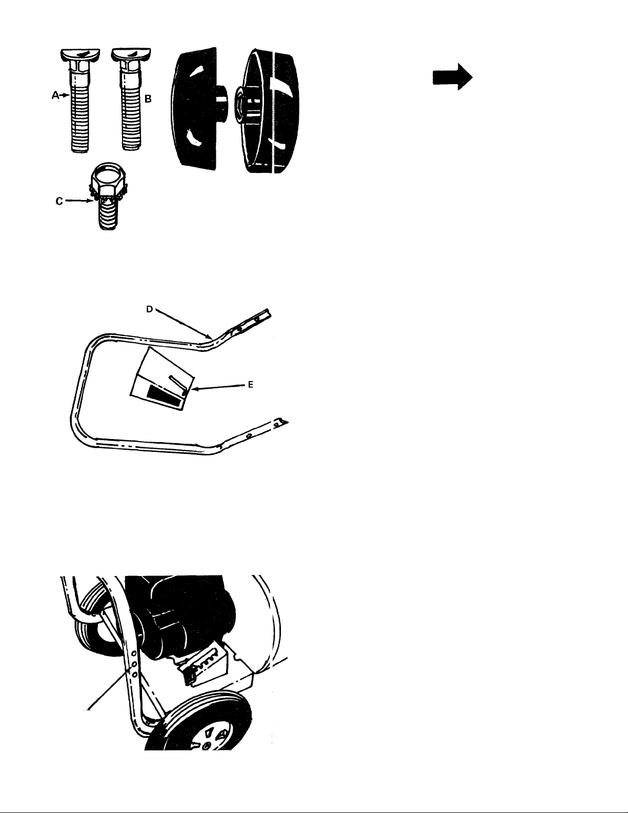
FIGURE 1.
ASSEMBLY INSTRUCTIONS
NOTE
Vacuum hose attachment 245-204-000
comes with model 694. It is optional
equipment on all other models.
CONTENTS OF HARDWARE PACK:
(See Figure 1)
A (2) Carriage Bolts
B (2) Hand Knobs
C (1) Hex Sems Bolt
FIGURE 2.
PARTS IN CARTON (See Figure 2):
D (1) Upper Handle
E (1) Directional Discharge
NOTE
The right and left side of your leaf
blower is determined from operator's
position.
1. Remove the leaf blower, hardware pack and all
literature from the carton before discarding
carton.
USE THIS
HOLE ONLY
FIGURE 3.
2. Figure 3 shows lower handle. Upper handle
mounts in center hole only.
Page 5

FIGURE 4.
Place the upper handle (D) over the lower handle,
lining up the holes. Secure with carriage bolts (A)
and hand knobs (B). See figure 4.
4. Slip end of directional discharge (E) over chute
opening. Secure in position with hex sems bolt
(C). See figure 5.
DIRECTIONAL
DISCHARGE (E)
FIGURE 5.
OPERATION
BEFORE STARTING ENGINE
Service engine with gas and oil. See engine manual
packed with leaf blower for complete instructions
'''or care and maintenance of engine. READ DIREC
TIONS CAREFULLY.
TO START ENGINE
2. Pull starter rope once with quick, full stroke.
Move hand throttle to "FAST" position and pull
starter rope again.
3. When engine starts, move throttle to "RUN"
position until engine warms up.
TO STOP ENGINE
1. Move throttle to "START" position.
Move throttle control lever to "OFF" position.
Page 6

ADJUSTMENTS
\C WARNING I
Do Not make this adjustment or any
adjustment with the engine running.
Stop the engine, disconnect the spark
plug wire and ground plug wire to
engine block.
TWO-WAY AIR DISCHARGE
Your leaf blower is equipped with an adjustable
chute deflector. Simply push down on handle provid
ed and swing door towards the front or side as dei ired.
See figure 6.
MAINTENANCE AND LUBRICATION
Your leaf blower, like all machines with moving parts
must receive care and maintenance. The following
tips, if used, will contribute many troublefree hours
to your blower.
1. Check oil level frequently. When changing oil,
make sure dirt and debris is cleaned off oil sump
before removing oil plug.
2. Keep blower clean, especially the engine and
engine air filter.
3. Check all nuts, bolts and screws occasionally to be
sure blower is in good operating condition.
4. The wheel bearings are pre-lubricated at the
factory and should require no further attention
until blower is serviced. However, it is advisable
to remove the wheels and apply a small amount
of light oil to each axle at least once a season.
DIRECTIONAL
DISCHARGE
FIGURE 6.
HEIGHT ADJUSTMENT
To adjust the height of the discharge, stand oi the
right hand side of the leaf blower and move the index
handle towards the engine. Move handle to\\/ards
rear of unit to lower height. Move the handle forward
to raise the height. See figure 7.
OFF-SEASON STORAGE
If you are going to store your blower for any length
of time (30 days or longer), it is important that the
following steps be taken:
1. Drain the gas tank. Start the engine. Allow it to
run out of gas. Gasoline left in the engine will
leave gum deposits in the carburetor and gas tank.
2. Clean engine of all foreign matter.
3. Lubricate cylinder by removing the spark plug
and pour in one ounce of clean lubricating oil
through the spark plug hole into the cylinder.
Crank engine slowly to spread oil and replace
spark plug. To start after storage, remove spark
plug and rotate engine with starter to remove
excess oil.
NOTE
FIGURE 7.
When storing any type of power
equipment in an unventilated or metal
storage shed, care should be taken to
rust proof the equipment. Using a
light oil or silicone, coat the equip
ment, especially springs and bearings.
Page 7

TROUBLE SHOOTING CHART
PROBLEM
1. Excessive
vibration.
2. Height adjust
ment slips out
of lockout
position.
3. Engine fails A. Check fuel tank for gas.
to start.
4. Hard starting A. Spark plug wire loose.
or loss of power.
5. Engine over
heats.
.OTE: For repairs beyond the minor adjustments listed above, please contact your local service dealer.
A. Bent crankshaft.
B. Vane plate out of balance.
B. Spark plug lead wire
C. Faulty spark plug.
B. Dirty air cleaner.
A. Carburetor not adjusted
B. Air flow restricted.
C. Engine oil level low.
CAUSE
Handle bent.
disconnected.
properly.
A. Replace crankshaft (should be done by an authorized service
dealer).
B. Replace vane plate.
Replace index handle and index plate.
A. Fill tank if empty.
B. Connect lead wire.
C. Spark should jump gap between control electrode and side
electrode. If spark does not jump, replace the spark plug.
A. Connect and tighten spark plug wire.
B. Clean air cleaner as described in engine manual.
A. Adjust carburetor. See engine manual.
B. Remove blower housing on engine and clean as described in the
engine manual.
C. Fill crankcase with the proper oil.
REMEDY
Page 8

Models 692, 693, 694 and 24695
34
L
35
\ ?
29
27
f
(%
If YOU WRITE TO US ABOUT THIS ARTI
OR IF YOU ORDER REPLACEMENT PART
WAYS MENTION THIS MODEL & SERIAL
REF.
PART NO.
NO.
749-0479 . Upper Handle
1
5
6
714-0114
710-0442
7 14526-488
8
9
10
11
736-0119 L.-Wash. 5/16" I.D.*
712-0267
736-0187
1544-009
12 712-0206
13
736-0921
14 734-1036
15
16
14571-488
710-0726
PARTS LIST FOR LEAF BLOWER MODELS 692, 693, 694 and 24695
COLOR
CODE
DESCRIPTION
PARI
REF.
NO.
PART NO.
COLOR
CODE
NEW
19 734-1035
Sq. Key 1/4" x 2.00"
Lg.*
Hex Bolt 5/16-18 X
734-1184 Wheel Ass.'y. Comp. 10.5"
1.50" Lg.*
Engine Mounting
Frame Ass'y.
Hex Nut 5/16-18 Thd.*
741-0313
736-0159
20
21 710-0170
Fl.-Wash. .63" I.D. x
1.25" O.D.
Cotter Pin 5/32" Dia. 27
X 1.25" Lg.*
Hex Nut 1/2-13 Thd.*
L.-Wash. 1/2" I.D.*
Swivel Caster Wheel 5'
Dia. X 1.25"
Caster Arm Ass'y.
Hex Wash. Hd. "AB"
22 736-0162
710-0118
28 14561
29
09966
31
720-0142
32 14552
34 749-0481
35
710-0487
Tap Scr. 5/16" X .7£ "
Lg.
**Tire Only - 734-1185, Rim Only - 734-1183.
DESCRIPTION
Wheel Ass'y. Comp. 12"
X 3.5" (Plastic-692 only)
(Incl. Bearings)
x4" (Steel)**
Bearings (For Steel Wheel)
Fl.-Wash. 34" I.D. x .87"
O.D.
Hex Locking Bolt 5/16-24
X .62" Lg.
Fl.-Wash.(692 only)
Hex Bolt 5/16-18 X .75"
Lg.*
Index Plate
Hand Knob
FI.-Grip Vinyl
Height Adj. Handle
Lower Handle
Carriage Bolt 5/16-18 x
2.0" Lg.
NEW
PART
Page 9

Models 692, 693, 694 and 24695
PARTS LIST FOR LEAF BLOWER MODELS 692, 693, 694 and 24695
REF.
NO.
1 14539
2
710-0600 Hex Self Tap Scr. 5/16" x .50" 15 14563 - 488
PART
NO,
COLOR
CODE
DESCRIPTION
Engine Housing Brace Ass'y-
Lg.
NEW
PART
REF.
NO.
14
16
PART
NO.
711-0758
710-0191
3 710-0118 Hex Bolt 5/16-18 X .75" Lg.* 17 736-0217
4 736-0119
5 14541
710-0627
6
7
710-0260
8 14479
- 488
L.-Wash. 5/16" I.D.* 18 14536 - 488
Right Angle Bracket
Hex Locking Bolt 5/16-24 x.75‘
\
22 710-0259
19
14496 -488
Carriage Bolt 5/16-18 x .62"
Lg.*
23 736-0242
Directional Discharge Ass'y. O.D.
11 736-0119 L.-Wash. 5/16" I.D.* 24 720-0170
12
712-0267 Hex Nut 5/16-18 Thd.*
13
731-0608
The engine is not under warranty by the leaf blower manufacturer. If repairs or service is needed on the
engine, please contact your nearest authorized engine service outlet. Check the "Yellow Pages" of your
telephone book under "Engines - Gasoline".
Blower Guard
*For faster service obtain standard nuts, bolts and washers locally. If these items cannot be
obtained locally, order part number and size as shown on parts list.
(488 - Mack Truck Yellow) When ordering parts if color or finish is important, use color code
(615 - Red) shown at left (e.g. Mack Truck Yellow Finish - 14542 (488).)
COLOR
CODE
DESCRIPTION
Hex Shoulder Nut .50" I.D.
Nozzle Plate Ass'y.
Hex Bolt 3/8-24 X 1.25" Lg.*
L.-Wash. 3/8" I.D. HD.
Air Vane Plate Ass'y.
Blower Housing Ass'y. - Comp.
Hex Sems Bolt 5/16-18 x .62"
Lg.*
Belleville Wash. 34" I.D. x .87"
3-Arm Thumb Scr. 5/16-18 x
.75" Lg.
Find It Fast
InTha
Yellow Pages
NEW
PART
Page 10

Page 11

Page 12

MTD PRODUCTS INC
.....................
..
..........
YaRD-MSN COMPANY
P.O. BOX 36900
CLEVELAND OHIO 44136
 Loading...