

Page 1
OUTDOOR POWER EQUIPMENT
for all seasons
.75
POWER
VACUUMS
Important:
Read Safety Rules and
Instructions Carefully
V
PRINTED IN U.S.A.
Model Numbers
245-675-000
245-685-000
245-689-000
24677S
24687S
Thank you for purchasing
an American-built product.
J
FORM NO. 770-3989
Page 2

INDEX
Safe Operation Practices
Assembly Instructions
Operation .........................
Adjustments .....................
Lubrication
.......
...............
r
♦
♦
♦
♦
♦
♦
♦
♦
For one year from the date of or ginal retail purchase, MTD PRODUCTS INC will either
repair or replace, at its option, fret of charge, F.O.B. factory or authorized service firm, any
part or parts found to be defective in material or workmanship. Transportation charges for
the movement of any power equip nent unit or attachment are the responsibility of the pur
chaser. Transportation charges fo' any parts submitted for replacement under this warran
ty must be paid by the purchaser i niess such return is requested by MTD PRODUCTS INC.
This warranty will not apply to an / part which has become inoperative due to misuse, ex
cessive use, accident, neglect, improper maintenance, alterations, or unless the unit has
been operated and maintained in iccordance with the instructions furnished. This warran
ty does not apply to the engine, m Dtor, battery, battery chargeror component parts thereof.
Please refer to the applicable manufacturer’s warranty on these items.
A,
3
4
9
9
10
instructions given with this symbol are
for personal safety. Be sure to follow
them.
Maintenance
Off-Season Storage
Illustrated Parts
Replacement Parts List
.....................................
..........................
................................
....................
LIMITIED WARRANTY
......................
..................12, 14
..................13, 15
10_
♦
♦
♦
♦
This warranty will not apply where the unit has been used commercially.
Warranty service is available thro jgh your local authorized service dealer or distributor. If
you do not know the dealer or distributor in your area, please write to the Customer Service
Department of MTD.
The return of a complete unit wil not be accepted by the factory unless prior written per
mission has been extended by MTD.
♦
♦
This warranty gives you specific legal rights. You may also have other rights which vary
from state to state.
V
àm ;
This unit is equipped with an internal combustion engine and should not be used on or near any unimproved
forest-covered, bursh-covered or grass-covered land unless the engine's exhaust system is equipped with a spark
arrester meeting applicable local or state laws (if any). If a spark arrester is used, it should be maintained in effect’working order by the operator.
In the State of California the above is required by law (Sectiori 4442 of the California Public Resources Code).
Other states may have similar laws. Federal laws apply on federal lands. A spark arrester muffler is available at your
nearest engine authorized service center.
Page 3

A
IMPORTANT
It is suggested that this manual be read in its entirety before attempting to assemble or operate. Keep this
manual in a safe place for future reference and for ordering replacement parts.
This unit is shipped WITHOUT GASOLINE or OIL. After assembly, see separate engine manual for proper
fuel and,engine oil recommendations.
SAFE OPERATION PRACTICES FOR POWER VACUUMS
1. Read this operating and service instructing manual
carefuHy. Be thoroughly familiar with the controls
and proper use of the power vacuum.
2. Never allow children to operate this power
vaccum.
3. Keep the area of operation clear of all persons,
particularly small children and pets.
4. Check fuel before starting engine. Do not fill fuel
tank indoors, when engine is running, or while
engine is hot. Wipe off any spilled fuel before
starting engine.
). Do not change engine governor settings.
6. Do not put hands near rotating parts for any
reason.
7. If the power vacuum should start to vibrate
abnormally, stop the engine and check immedi
ately for the cause. Vibration is generally a
warning of trouble.
10. Check all bolts for tightness at frequent periods.
11. Never store this power vacuum with fuel in the
tank. Allow engine to cool before storing in
any enclosure.
12. Keep bag and equipment free of debris when not
in use.
13. Never operate this power vacuum unless air duct
and vacuum bag are properly affixed in their
place. Large zippered end of bag must be closed
when operating to prevent objects from being
blown out.
14. Never empty vacuum bag when engine is running.
15. Never change inlet nozzle or auxiliary hose attach
ment when engine is running.
16. The manufacturer recommends that the operator
wear safety glasses or some other suitable eye
protection when operating this machine.
8.
Before cleaning, repairing or inspecting, make
certain all moving parts have come to a complete
stop. Disconnect spark plug wire and keep wire
away from plug to prevent accidental starting.
Also keep throttle control lever in the stop
position.
9.
If the power vacuum should become blocked with
debris at any point, shut engine off and wait
until the impeller comes to a complete stop
before attempting to remove the obstruction.
Disconnect spark plug wire to prevent accidental
starting.
17. Check the vacuum bag frequently for wear and
replace when necessary.
18. Never operate as a leaf blower unless impeller
guard and guard assembly are properly affixed in
their place.
19. Exercise caution whenever operating as a leaf
blower. Do Not allow discharge to be pointed in
the direction of persons.
20. No one should operate this unit while intoxicated
or while taking medication that impairs the senses
reactions.
Page 4
H
ASSEMBLY
INSTRUCTIONS
FIGURE 1
® i
1T f J ®®@®
@ © ® •■'^ -
K-*l
M
I
CONTENTS OF HARDWARE PACK
(See figure 1)
A (1) Clutch Grip Assembly*
B (1) Hair Pin Cotter*
C (1) Clevis Pin*
D (1) Extension Spring*
E (1) Lock Nut 1/4-20 Thread*
F (3) Hand Knobs
G (3) Belleville Washers
H (1) Heavy Flat Washer
I (4) Hex Bolts 1/4-20 x 1.75" Long
J (4) Hex Lock Nuts 1/4-20 Thread
K (2) Stud Pins
L (2) Push-on Speed Nuts
M (1) Hex Jam Nut 1/4-20 Thread*
LOOSE PARTS IN CARTON
(See figure 2)
N (1) Nozzle
0 (1) Upper Handle
P (1) Air Duct Assembly
Q (1) Clutch Rod*
R (1) Directional Discharge Assembly
S (1) Impeller Guard
T (1) Bag
*Self-Propelled Models Only.
FIGURE 2
w-
FIGURE3
TOW BAR KIT- Standard with push models.
figure 3) Optional with self-propelled
(See
U
V
w (2)
X
Y
z
AA
AB (2)
AC
Hex Bolts 5/16-18 X 1.00" Long
(2)
Shoulder Spacers
(4)
Hex Nut 5/16-18 Thread
Truss Machine Screw 1/4-20 x .75"
(1)
Lock Washer 1/4" I.D.
(1)
Hex Nut 1/4-20 Thread
(1)
Shoulder Bolt
(1)
Belleville Washers 3/8" I.D.
Hex Jam Lock Nut 3/8-16 Thread
(1)
Tow Bar Halves (Not Shown)
(2)
Page 5
NOZZLE(N)
FIGURE 4
UPPER
HANDLE (O)
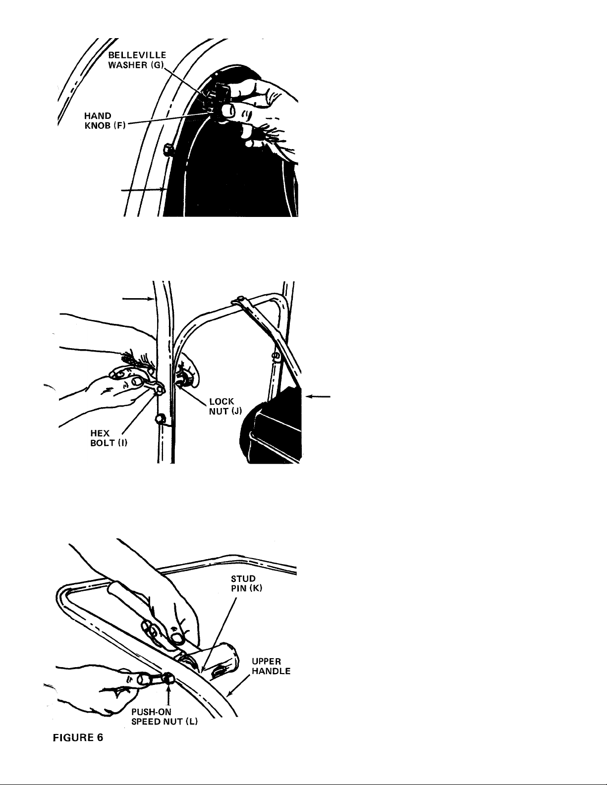
Place nozzle (i\l) in position on front of housing
so that it rests in flanges. Secure with one hand
knob (F) and belleville washer (G). See figure 4.
2. Place the upper handle (0) in position over lower
handle. Fasten with four hex bolts (I) and lock
nuts (J) provided. See figure 5. Two 7/16"
wrenches are required.
FIGURE 5
3. Place the stud pins (K) in holes in upper handle
(head of pins go to the inside of handle). Secure
pins with push-on speed nuts (L) by holding
speed nut with box wrench and tapping pin with
hammer. See figure 6.
Page 6

HAND
KNOB (F)
FIGURE 7
Place air duct assembly (P) over opening on top
of housing. Secure with two hand knobs (F) and
belleville washer (G). See figure 7.
FIGURES
STUD PIN
ON HANDLE
BAG (•■)
Assemble the bag by slipping the top straps on
5.
bag (T) over upper handle. Hook two small straps
over stud pins on handle. Slip elastic opening of
bag over air duct assembly. See figure 8.
NOTE
Be certain elastic on bag is placed over
the flanges on air duct assembly.
NOTE
Steps 6, 7, 8 and 9 are for self-propelled
units only.
FIGURE 9
Assemble the clutch grip (A) to the left hand
6.
side of upper handle. Secure in place with clevis
pin (C) and hair pin cotter (B). See figure 9. Head
of clevis pin should be to the outside of handle.
Page 7

FIGURE 10
CLUTCH
BRACKET
ASSEMBLY
ROD (Q)
7.
Slide the extension spring (D) onto clutch rod (Q)
as shown in figure 10. Thread lock nut (E) onto
clutch rod approximately 2-1/2 inches.
8.9.Hook top (hooked end) of clutch rod into clutch
grip. Hook spring into clutch bracket assembly.
See figure 11. Spring should not have any slack.
Adjust nut so that when the clutch grip is all the
way up, there is no slack in the spring.
Thread hex jam nut (M) onto clutch rod, and
lock it against the lock nut (E).
FIGURE 11
ASSEMBLY INSTRUCTIONS
To Convert from a Vacuum to a Leaf Blower.
WARNING
Ac
Engine must be stopped (off) and
spark plug wire disconnected.
1. Remove the bag.
2. Remove the air duct assembly by removing two
hand knobs and belleville washers.
3. Remove the nozzle by removing one hand knob
and belleville washer.'
4. Remove the hand knob and belleville washer
holding the housing to engine brace. See figure 12.
Page 8

5. Lift up and out on the housing and rotate it 105°
clockwise. Chute opening should be to the righ^
hand side when viewed from the front of unit.
See figure 13.
6. Place the impeller guard (S) into flanges on front
of housing. Line up hole in guard with hole on
housing. Secure with one hand knob, belleville
washer and heavy flat washer (H). See figure 13.
FIGURE 14
HEX
NUT (W)
HEX
BOLT(U)
SHOULDER
SPACERS(V)
FIGURE 15
HAND KNOB
TRUSS
MACHINE
SCREW (X),
SHOULDER'
BOLT (AA)
DIRECTIONAL
DISCHARGE
ASSEMBLY (R)
BELLEVILLE
WASHER (AB)
HEX JAVI
LOCK ^ UT
(AC)
BELLEVIL-E
WASHER (ДВ)
HI ГСН
PLATE
7. Place the directional discharge assembly (R) over
chute opening. Secure with two hand knobs and
belleville washers. See figure 14.
ASSEMBLY INSTRUCTIONS
for Tow Bar Kit (Optional)
1. Remove the self-tapping screws on each side of
frame. Refer to drawing on page 12, reference
number 42.
2. Place tow bar half in position on frame. Place
one shoulder spacer (V) between frame and
tow bar. Next, place shoulder spacer (V) and hex
bolt (U) through tow bar and frame. Secure with
hex nut (W). See figure 15. Repeat for other side.
3. Secure the two tow bar ends together with truss
machine screws (X), lock washers (Y) and hex
nuts (Z). See figure 15.
To attach the tow bar to a hitch, place the shoulder
bolt (AA) up through the tow bar. Place one bellevillt
washer (AB) on the shoulder bolt, then the hitch
place and the other belleville washer. Cupped side of
the washers must be against the hitch plate. Secure
with hex jam lock nut (AC). See figure 15.
Page 9

OPERATION
PRE-START PREPARATIONS
"^vice engine with gas and oil. See engine manual
xked with vacuum for complete instructions for
care and maintenance of engine. READ DIREC
TIONS CAREFULLY.
A
CAUTION
REVOLVING BLADES-KEEP
HANDS AWAY FROM ALL
OPENINGS
TO START ENGINE
After the engine has been properly fueled and oiled
(refer to engine operating and maintenance instruc
tions), start engine following the instructions below.
1. Move throttle control lever on engine to START
position.
2. Crank engine. Pull recoil with quick firm pull.
Do not pull out so far the rope stops with-a jerk
as this will cause rope failure. Do not allow rope
and handle to snap back into place.
3. After two or three full firm pulls on recoil (or as
soon as engine fires), move speed control to
RUN position.
4. Self Propelled Models Only - To engage the drive
mechanism, squeeze the clutch grip against the
upper handle. Release the clutch grip to stop the
forward motion.
ADJUSTMENTS
CAUTION
A
Do not at any time make any adjust
ment to the unit without first stopping
engine and disconnecting spark plug
wire.
HEIGHT ADJUSTMENT
To adjust the height of the nozzle, stand on the right
hand side of vacuum and move the index handle
towards the engine. Move handle towards rear of unit
to lower height. Move the handle forward to raise the
height. See figure 17.
TO STOP ENGINE
1. To stop engine, move throttle control lever to
STOP position.
2. Disconnect spark plug wire and ground to prevent
accidental starting while equipment is unattended.
Operate a new engine at intermediate speeds and light
load for the first few hours as you would a new
automotive engine.
IMPORTANT
The vacuum bag may have an air escape
located on the upper right hand side.
See figure 16. The air escape can be
opened if the vacuum is operated in
wet, sandy or muddy conditions.
FIGURE 17
Page 10

CARBURETOR ADJUSTMENT
A
If any adjustments are made to the
engine while the engine is running
(e.g. carburetor), disengage all clutches.
Keep clear of all moving parts. Be
careful of heated surfaces and muffler.
If carburetor needs adjustment to start or for oper
ation, see "Carburetor Adjustment" section of engine
manual.
CLUTCH ROD ADJUSTMENT {Self Propelled Models
Only)
To adjust the clutch rod, refer to step numbers 15 and
9 under assembly instructions.
^ WARNING ^
LUBRICATION
Wheels - Rear wheels are provided with oil lite
bearings. Place a few drops of SAE 30 oil on each
bearing once a season.
Gear Box (Self Propelled Models Only) - The gear box
lubricated with 2 ounces of High Temp. (45(1° F.)
grease. Order part number 737-0133. Period cally
check lubricant level by removing the two self-taDping
screws on the gear box cover and lifting off the
cover. Do not change grease; simply add if necesi ary.
MAINTENANCE
) WARNING {
A
Disconnect spark plug wire and ground
it against the engine before performing
any repairs or maintenance.
BELT REPLACEMENT (Self Propelled Models Only)
1. Remove the nozzle or impeller guard from front
of blower housing.
2. Remove hex bolt and lock washer from cen ler of
impeller. See figure 18. A 9/16" socket wench
with extension is needed.
3. Remove hand knob and belleville washer from
top of housing.
4. Remove two self-tapping screws which hoM the
belt guard. See figure 19. A 3/8" wrench is
required. Lift off belt guard.
FIGURE 19
5. Slide belt off the impeller pulley. Slide housing
and impeller off engine crankshaft. Be careful
to not lose square key. See figure 20.
ENGINE
CRANKSHAFT
P.T.O.
PULLEY
FIGURE
10
Page 11

6. Slide impeller and blower housing assemblies off
crankshaft.
OFF-SEASON STORAGE
7. Remove belt from P.T.O. pulley and install new
belt. See figure 20.
NOTE
When reassembling the new belt, the
aid of another person will be helpful.
8. Turn the crankshaft until the key way on shaft is
directly on top. While holding housing assembly
and impeller assembly, line up the key way on the
pulley with the key on the crankshaft, and slide
housing and impeller assemblies onto crankshaft.
9. Secure impeller to crankshaft with hex bolt and
lockwasher, removed in step 2. Tighten securely.
10. Slip belt over impeller pulley and reassemble the
belt guard.
11. Secure blower housing with hand knob and
washer.
12. Reassemble the nozzle or impeller guard.
The following steps should be taken to prepare the
unit for storage.
1. Clean the engine and the entire unit thoroughly.
2. Refer to engine manual for correct engine storage
instructions.
3. Store unit in a clean, dry area.
NOTE
When storing any type of power
equipment in an unventilated or metal
storage shed, care should be taken to
rustproof the equipment. Using a light
oil or silicone, coat the equipment,
especially springs and bearings.
PROBLEM CAUSE
1. Excessive
vibration.
2. Height adjust
ment slips out
of lockout
position.
3. Engine fails
to start.
4. Hard starting
or loss of power.
5. Engine over
heats.
A. Bent crankshaft.
B. Vane plate out of balance.
Handle bent.
A. Check fuel tank for gas.
B. Spark plug lead wire
disconnected.
C. Faulty spark plug.
A. Spark plug wire loose.
B. Dirty air cleaner.
A. Carburetor not adjusted
properly.
B. Air flow restricted.
C. Engine oil level low.
TROUBLE SHOOTING CHART
REMEDY
A. Replace crankshaft (should be done by an authorized service
dealer).
B. Replace vane plate.
Replace index handle and index plate.
A. Fill tank if empty.
B. Connect lead wire.
C. Spark should jump gap between control electrode and side
electrode. If spark does not jump, replace the spark plug.
A. Connect and tighten spark plug wire.
B. Clean air cleaner as described in engine manual.
A. Adjust carburetor. See engine manual.
B. Remove blower housing on engine and clean as described in the
engine manual.
C. Fill crankcase with the proper oil.
NOTE: For repairs beyond the minor adjustments listed above, please contact your local service dealer.
11
Page 12

Models 675, 685 and 689
IF rOU WRITE TO US ABOUT THIS ARTICIE
OR IF YOU ORDER REPLACEMENT PARTS AL
WAYS MENTION THIS MODEL & SERIAL NO
MODEL
12
Page 13

675/685/689
PARTS LIST FOR MODELS 675, 685, 689, 24677 and 24687 POWER VACUUMS
.fcF.
PART
NO.
1
2
3
4
5
6
7 14558
8
9
10
COLOR
NO.
CODE
05778
711-0679
747-0154 Clutch Rod 32" Lg. t
749-0482
749-0484 Handle Brace (8 H.P.)
710-0776
714-0114
14536-488
14557-488
710-0442 Hex Bolt 5/16-18 X 1.50"*
Clutch Grip Ass'y-t
Clevis Pin .375" Dia. x 1.88" 40 748-0135
Lg. t
Handle Brace (5 H.P.) X 1.25" Lg. t
Part of Engine
Hex Wash. Hd. AB Tap Scr. 43
1/4" X .62" Lq. t 44 736-0119 L.-Wash. 5/16" I.D.*
Belt Guard t 45
Square Key 1/4" x 1/4" x 46
2.00" Lg.
Air Vane Plate Assy. (675 and
677)
Air Vane Plate Ass'y- w/pulley t
DESCRIPTION
11 754-0219 "V"-Belt 1/2" X 26" Lg. t
L.-Wash. 5/16" I.D.*
Hex Nut 5/16-18 Thd.*
Engine Mounting Frame
Ass'y-
Cotter Pin 5/32" Dia. x 1.25"* 734-1184
Fl.-Wash. .63" I.D. x 1.25"
O.D.
L.-Wash. 1/2" I.D.*
Hex Nut 1/2-13 Thd.*
Hex Cent. L.-Nut 1/4-20 Thd.
Extension Spring .78" O.D.
x .750" Lg. t
Swivel Caster Wheel 5" Dia. 56
X 1.25"
Extension Spring .38" O.D.
X 7.50" Lg. t
Snap "E"-Ring .50" Dia.
Shaft t 61
"V"-Pulley 5/8" x6.50" O.D.t
Flange Bearing .502" I.D. t 63
Gear Box Mounting Bracket t
Extension Spring .75" O.D. x
3.28" Lg. t
Clutch Bracket Ass'y. t
#2 Woodruff Key 3/32" Dia.
X .81" Lg. t
Hex Flange Bearing Bronze
.625" I.D. t
Pinion Shaft .50" Dia. x5.0"t
Gear Box Ass'y. Comp, t
Caster Arm Ass'y.
Drive Shaft .624" Dia. x
22.75" Lg. t
Bevel Gear .50" I.D. x 14
Teeth
Flange Bearing .503" I.D. t
Gear Box t
Flange Bearing .630" I.D. t
13
14
15
16
18
19
736-0119
712-0267
14527-488
1544-009
736-0187
736-0921
712-0206
712-0107
732-0411
12
20
21 734-1036
22
31
"Цб
tParts for Self-Propelled Units (Models 685,689, and 24687) only.
732-0409
716-0104
23
756-0367
24
748-0142
25
14570
26
27 732-0376
14565
28
714-0229
29
748-0227
30
738-0516
717-0493
32
14571-488
33
34 08348
35 748-0136
748-0108
37 08189
748-0110
38
NEW
PART
PART
REF.
NO.
39 08187
41
42
47 14530-488 Side Plate
48 715-0247 Spring Pin Spiral 3/16" Dia.
49 748-0288 Drive Pinion t
50 710-0170
51 736-0159
53 734-1035 Wheel Ass'y. - Comp. 12" x 3"
54
55 710-0118 Hex Bolt 5/16-18 X .75" Lg.
57
58 14561 Index Plate
59
60
62
64 749-0481
65
66
67 711-0737 Stud Pin .250" Dia. X 1.75"
68 710-0136
69 714-0145
70
71 738-0185
72 715-0249
73
74 736-0175 L.-Wash. .265" I.D. t
75
76
77 712-0298 Hex Jam Nut 1/4-20 Thd. t
78
79
COLOR
NO.
CODE
Gear Box Cover t
Bevel Gear .62" I.D. x 28
Teeth t
715-0246
710-0726
712-0267 Hex Nut 5/16-18 Thd.*
736-0119
748-0201 Spacer .63 I.D. x .88" O.D.
741-0313 Bearings (677 Only)
750-0194 Spacer .63" I.D. x 1.00" O.D.
748-0192
712-0267 Hex Nut 5/16-18 Thd.*
720-0142
710-0118 Hex Bolt 5/16-18 X .75" Lg.*
712-0107 Hex Cent. L.-Nut 1/4-20 Thd.
710-0136
764-0162
1539-019 Push Speed Nut .25" Dia. Stud
712-0287 Hex Nut 1/4-20 Thd.*
736-0329 L.-Wash. 1/4" I.D.*
749-0480 Upper Handle
750-0142 Spacer .82" I.D. x 1.00" O.D.
710-0352 Hex Self Tap Scr. 1/4" x
14556
14555 L.H. Pinion Guard (Not Shown
736-0242 Belleville Washer
14552
Spring Pin Spiral 3/16" Dia.
Hex Wash. Hd. "AB" Tap Scr.
5/16" X .75" Lg.
L.-Wash. 5/16" I.D.*
X .56" Lg. t
x1.0"Lg. t
Hex Locking Bolt 5/16-24
X .62" Lg.
Fl.-Wash. .34" 1.D. x87" O.D.
(Incl. Ball Bearings)
Wheel Ass'y. Comp. 10.5"
X 4"'{677 Only)
X .94" Lg. (675,685,687)
Spacer .63" I.D. x .878" O.D.
X .79" Lg. (677)
Flat Grip Vinyl
Hex Bolt 1/4-20 X 1.75" Lg.
Vacuum Bag - Felt
Lower Handle
Hex Bolt 1/4-20 X 1.75" Lg.*
internal Cotter Pin 3/8" Dia.
Rear Axle .624" Dia. x 24.37"
Spring Roll Pin 5/32" Dia.
X 1.12T
X .305 Lg. t
3/8" Lg. t
R.H. Pinion Guard t
Height Adj. Handle oftXJQR-
DESCRIPTION
Ш Of Casicir /VrX
13
NEW
PART
Page 14

Models 675, 685 and 689
14
Page 15

Models 675, 685 and 689
PARTS LIST FOR MODELS 675,685,689, 24677 and 24687 POWER VACUUMS
Ref.
No.
Part
No.
Color
Code
Description
New
Part
1 14532 --
2 736-0242
3 720-0170
4 749-0501
5 731-0608
8 14479
14562
9
488 Air Duct Assembly
Belleville Wash. 34" I.D. x .87" O.D.
3-Arm Thumb Scr. 5/16-18 x .75" Lg.
Tow Bar Half
Impeller Guard
Directional Discharge Ass y.
Nozzle Ass'y-
10 14563 Nozzle Plate Ass'y-
712-0267 Hex Nut 5/16-18 Thd.*
11
12 736-0119
710-0191
13
736-0217
14
15 14536 - 488
14557 -
14496 - 488
16
17 14541
710-0600
18
711-0758
20
710-0260
21
488
22 710-0627
23
24 728-0143
25
26
28
29
30
31
32
34 738-0143
35
36
14539
14569
735-0214
710-0602
710-0255
712-0287
736-0329
748-0234
736-0219
712^0181
L.-Wash. 5/16" I.D.
Hex Bolt 3/8-24 X 1.25" Lg.*
L.-Wash. 3/8" I.D. H.D.
Air Vane Plate Ass'y. (675 and 24677)
Air Vane Plate Ass'y. w/pulley (685, 689 and
24687)
Blower Housing Complete
Right Angle Bracket
Hex Wash. Hd. Self Tap Scr. 5/16-18 x
.50" Lg.
Hex Shoulder Nut .50 I.D.
Carriage Bolt 5/16-18 x .62" Lg.*
Hex Locking Bolt 5/16-24 x .75" Lg.
Housing - Engine Brace Ass'y.
Pop Rivet (5-Required)
Wiper Retaining Strip
Nozzle Wiper
Hex Bolt 5/16-18 X 1.00" Lg.* t
Truss Mach. Scr. 1/4-20 x .75" Lg.* ^
Hex Nut 1/4-20 Thd.*t
L.-Wash. 1/4" I.D.*t
Shoulder Spacer t
Shid. Bolt .496 Dia. t
Belleville Wash. .39 I.D. x 1.12 O.D. t
Hex Jam L-Nut 3/8-16 Thd. t
tOptional Parts
*For faster service obtain standard nuts, bolts and washers
locally. If these items cannot be obtained locally, order by
part number and size as shown on parts list.
(488 - Mack Truck Yellow)
(615 - Red)
When ordering parts, if color or finish is important use the
appropriate color code shown above, (e.g. Mack Truck
Yellow Finish — 14542 (488).
This instruction manual covers various
models and all specifications shown do not
necessarily apply to your model. Specifica
tions subject to change without notice or
obi igation.
___________
NOTE
15
NOTE: The engine is not under warranty by
the vacuum manufacturer... If repairs or
service is needed on the engine, please
contact your nearest author
ized engine service outlet.
Check the “Yellow Pages" of
your telephone book under
"Engines—Gasoline.”
Find It Fast
In The
Yellow Pages
Page 16

MTD PRODUCTS INC
......................
............................
YaRD- M8N COMPANY
P.O. BOX 36900
CLEVELAND OHIO 44136
 Loading...