

Page 1
■'x
$1.00
OWNHrS GUIDE
ASSEMBLY • OPERATION • MAINTENANCE • PARTS
Model Numbers
249-650-000
5 H.R
24650-9
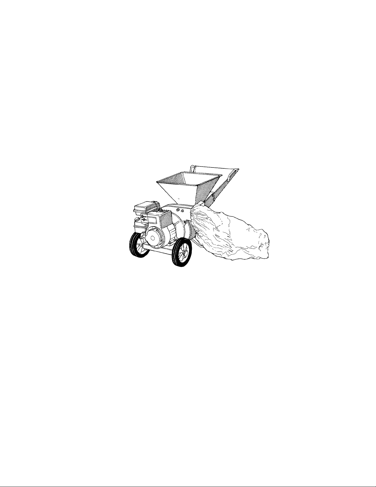
SHREDDER
Important: Read Safety Rules and Instructions Carefully
PRINTED IN U.S.A.
FORM NO. 770-5902D
Page 2

INDEX
Rules for Safe Operation..............................................................................3
Assembly.............................................................................................. . . 4
Operation........................................................................................................6
Adjustments.................................................................................................. 8
Ins uructions given with this sym
bol are for personal safety. Be
A
suie to follow them.
Maintenance ..................................................................................................9
Off-Season Storage ......................................................................................9
Trouble Shooting Chart ............................................................................11
Repair Parts ......................................................................................12, 13
A
This unit is equipped with an internal combust on engine and should not be used on or near any unproved
forest-covered, brush-covered or grass-covered laid unless the enigne's exhaust system is equipped with a spark
arrester meeting applicable local or state laws (if any). If a spark arrester is used, it should be maintained in
effective working order by the operator.
In the State of California the above is required bv law (Section 4442 of the California Public Resources Code).
Other states may have similar laws. Federal law at?ply on federal lands. A spark arrester for the muffler is available
through your nearest engine authorized service dealer.
{ warning {
i
2
Page 3

♦
■N
WARNING
At;
To reduce the potential for any injury, comply with the following safety instruc
♦
tions. Failure to comply with the instructions may result in personal injury.
RULES FOR SAFE OPERATION
TRAINING
1. Read this owner's manual carefully in its entirety
before attempting to assemble or operate this
machine. Be completely familiar with the controls
and the proper use of this machine before operating
it. Keep this manual in a safe place for future and
regular reference and for ordering replacement
parts.
2. Children must never be allowed to operate this
equipment.
3. No one should operate this unit while intoxicated or
while taking medication that impairs the senses or
reactions.
4. This equipment should never be operated in the
vicinity of children, pets or other persons.
5. Never run your machine in an enclosed area as the
exhaust from the engine contains carbon monox
ide, which is an odorless, tasteless and deadly
poisonous gas.
6. Never allow your hands or any part of your body or
clothing inside the feeding chamber, discharge
chute, or near any moving part while the machine
or engine is running.
7. If it is necessary for any reason to inspect or repair
the feeding chamber or any part of the machine
where a moving part can come in contact with your
body or clothing, stop the machine, allow it to cool,
and disconnect the spark plug wire from the spark
plug before attempting such inspection or repair.
PREPARATION
1. Wear safety glasses provided with your unit
while operating the chipper-shredder to prevent in
jury from any chips which may be ejected out of
the openings.
2. Wear proper apparel. Avoid wearing loose fitting
clothing. Wear gloves when handling material.
3. HANDLE FUEL WITH CARE as gasoline is an
extremely flammable fuel.
A. Check the fuel before starting the engine. Do
not fill the fuel tank indoors, while the engine
is running, or while the engine is still hot. Turn
the unit off and let the engine cool before
refueling.
B. Fuel your shredder in a clean area. Do not
smoke while refueling.
C. Fuel tank cap must be secure at all times
except during refueling.
D. Avoid spilling gasoline or oil. Wipe the unit
clean of any spilled fuel or oil.
E. Store fuel and oil in approved containers, away
from heat or open flame, and out of reach of
children.
4. This machine should be operated only upon an
level earthen surface.
5. Assure that all screws, nuts and bolts and other
fasteners are properly secured.
OPERATION
1. When feeding shreddable material into this equip
ment, be extemely careful that pieces of metal.
rocks, bottles, cans or other foreign objects are not
included.
2. If the cutting mechanism strikes any foreign object
or if your machine should start making an unusual
noise or vibration, immediately stop the engine and
disconnect the spark plug wire from the spark plug.
Allow the machine to stop and take the following
steps:
A. Inspect for damage.
B. Replace or repair any damaged parts.
C. Check for any loose parts and tighten to assure
continued safe operation.
3. The engine must be kept clean of debris and other
accumulations.
4. Do not allow an accumulation of processed material
to build up in the discharge area as this will pre
vent proper discharge and can result in kick-back
from feed opening.
5. Never allow your hands or any other part of your
body or clothing inside the feeding chamber,
discharge chute or near any moving part while the
engine is running.
6. Keep all guards and deflectors in place and in
good working condition to assure continued safe
operation.
7. Always stand clear of the discharge area when
operating this machine.
8. Keep your face and body back from the feed
opening to avoid accidental bounce back of any
material.
9. Do not over-reach. Keep proper balance and
footing at all times.
10. The engine governor settings on your machine
must not be altered, changed, or tampered with.
The governor controls the maximum safe operating
speeds and protects the engine and all moving
parts from damage caused by overspeed.
11. Do not transport machine while engine is running.
12. Do not operate engine if air cleaner or cover
directly over carburetor air intake is removed,
except for adjustment. Removal of such parts
could create a fire hazard.
MAINTENANCE AND STORAGE
1. When this equipment is stopped for servicing,
inspection, storage or to change an accessory,
make sure the spark plug wire is disconnected from
the spark plug. The machine should be allowed to
cool down before making such inspection, ad
justments, service, eta Maintain your machine with
care and keep it clean for the best and continued
safe operation.
2. Do not use flammable solutions to clean the air
filter.
3. When not in use, your machine should be stored out
of the reach of children. Keep where gasoline fumes
will not reach an open flame or spark. For long
periods of storage, the gasoline should be drained
and disposed in a safe manner. Always allow the
machine to cool before storing in any enclosure.
Page 4
NOTE
This unit is shipped WITHOUT GASOLINE
or OIL. After assembly, see separate
engine manual for proper fuel and engine
oil recommendations.
ASSEMBLY INSTRUCTIONS
Tools Required for Assembly:
(2) 7/16" Open End or Box Wrenches*
(1) 1/2" Socket Wrench
* An Adjustable Wrench may be used in place of one
of the wrenches.
FIGURE 1.
NOTE
The right and left side of your shredder
is determined from behind the unit.
UNPACKING
Remove the shredder and loose parts from the
carton. Make certain ail parts and literature have been
removed before the carton is discarded.
Parts in Carton:
Shredder
Chute Deflector
Hopper
Upper Leaf Ramp Section
Catcher Bag
Hardware Pack
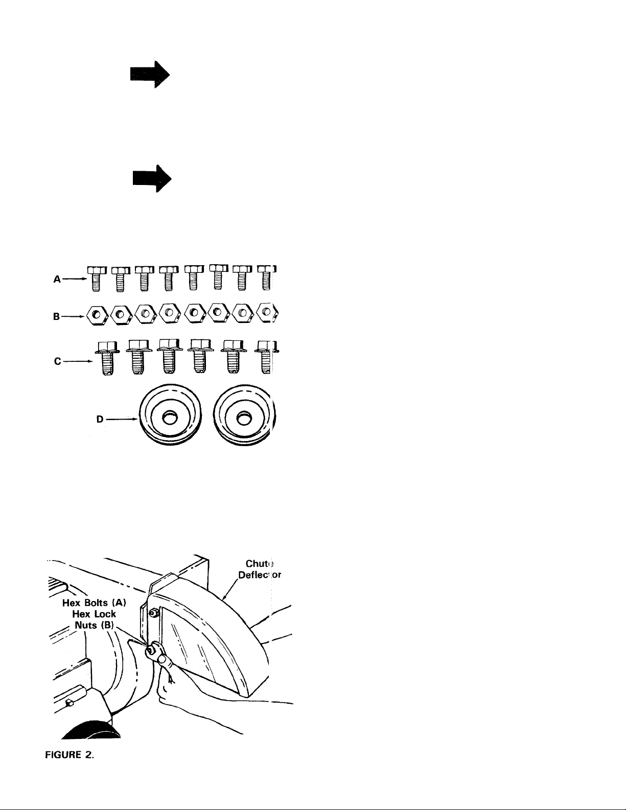
Contents of Hardware Pack (See Figure 1):
A
B (8)
C (6)
D (2)
Hex Bolts 1/4-20 x 1/2" Long
(8)
Hex Lock Nuts 1/4-20 Thread
Hex Washer Head Self-Tapping Screws
5/16-18 X 3/4" Long
Keepers
Safety Glasses (Not Shown)
(1) :
CHUTE DEFLECTOR INSTALLATION
1. Place the chute deflector in position on the
discharge opening (on the left side of the shred-
------
der). See figure 2.
2. Secure chute deflector to discharge opening with
hex bolts (A) and hex lock nuts (B). Heads of the
hex bolts are inside the discharge opening. Hex nuts
go on the outside.
3. Tighten all four nuts and bolts securely.
Page 5
Hopper’^
FIGURE 3.
Lower Leaf
Ramp Section
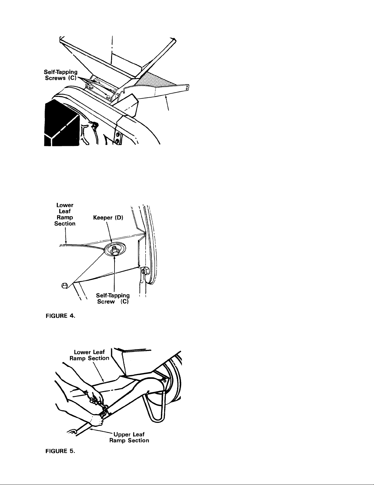
INSTALLATION OF HOPPER AND UPPER GUIIDE
EXTENSION
1. The lower leaf ramp section on the shredder is
placed in an upright position for shipping
purposes. Lower this section.
2.
Place the hopper in position on the shredder.
See figure 3. Start all four hex washer head self
tapping screws (C), then tighten securely using
a 1/2" socket wrench.
Assemble the keepers (D) to the sides of the unit
3.
with two hex washer head self-tapping screws (C),
using a 1/2" socket wrench. Tighten securely.
I I
4. Place upper leaf ramp section inside the lower leaf
ramp section. Secure with four hex bolts (A) and
hex lock nuts (B). Tighten securely. See figure 5.
Page 6

ATTACHING THE CATCHER BAG
Your unit is equipped with a nylon bag which attaches
to the discharge opening. If desired, place the end of
the bag over the chute deflector. Depress plunger, pull
on the drawstring, and release plunger to lock it in
• position. See figure 6.
OPERATION
GAS AND OIL FILL UP
NOTE
ENGINE IS SHIPPED WITHOUT OIL. FILL
CRANKCASE WITH OIL BEFORE STAR
TING.
Service engine with gasoline and oil as instruc ed in
the separate engine manual packed with your shred
der. Read instructions carefully.
TO START ENGINE
1. Attach spark plug wire to spark plug.
2. Place choke lever on engine in CHOKE pos tion.
See figure 7 or 7A.
NOTE
A warm engine may not require
choking.
3. Place the throttle control lever on engine in 7\ST
position.
Throttle Control
Lever in Start
Position
Choke
Lever
Tecumseh Engine
Grasp starter handle (see figure 8) and pull rope
out slowly until engine reaches start of compres
sion cycle (rope will pull slightly harder at this
point). Let the rope rewind slowly.
NOTE
FIGURE 7. - Briggs and Stratton Engine
A noise will be heard when finding
the start of the compression cycle. This
noise is caused by the flails and fingers
which are part of the shredding
mechanism falling into place, and
should be expected.
Pull rope with a rapid, continuous, full arm stroke.
5.
Keep a firm grip on start handle. Let rope rewind
slowly. Do not let starter handle snap back
against starter.
Repeat preceding instructions 4 and 5 until
6.
engine fires.
7.
After engine starts, move throttle control lever on
engine to slow position for a few minutes warm
up. Move choke lever gradually to RUN position.
Then move throttle control lever to FAST posi
tion for shredding operations.
Page 7

TO STOP ENGINE
1. Move throttle control lever to OFF position.
Air
Screen
If it becomes necessary to push materials into the
shredder, use a small diameter stick, NOT YOUR
HANDS. The stick should be small enough that it will
be ground up if it gets into the impeller assembly.
WARNING
Ac
Do not deposit material larger then 1/2"
diameter in the hopper or upper guide
extension. Any material heavier then 1/2”
should be fed into the chip-it guide.
2. Disconnect spark plug wire from spark plug and
ground against the engine to prevent accidental
starting while equipment is unattended.
HOW TO USE YOUR SHREDDER
Your shredder is designed for safe, efficient operation.
KEEP HANDS AND FEET AWAY FROM ALL OPENINGS.
AC WARNING \
Wear the safety glasses provided with
your unit while operating the shredder to
prevent injury from any chips which may
be ejected out of the openings. Make
certain chip-it guide is closed when not
in use.
Wear gloves when handling material. Feed material in
to the shredder at a steady rate. It is possible to feed
too fast. Experiment with feeding rates to determine
what rate provides the best results without stalling the
engine or plugging the discharge chute.
The discharge chute will direct the shredded material
into a pile, a container or the bag provided with your
shredder.
Leaves and smaller branches can be fed into the
hopper with the leaf ramp raised as shown in figures
9 and 10.
No larger than
1/2 inch diameter
^^Hopper
Chip-it
Guide
Ac WARNING \
The shredder discharges material with
considerable velocity. Keep away from the
area around the discharge chute. Always
stop the engine and disconnect the spark
plug wire when removing or attaching the
bag, when changing containers or when
removing the shredded material.
Leaf
Ramp
FIGURE 10.
Page 8

Lower the leaf ramp by holding the handle and pulling
up on the release bar. See figure 11. Leaves and snail
twigs can be raked into the shredder with the leaf ra mp
in this position. See figure 12.
NOTE
Bulky material, such as stalks or heavy
branches (anything up to 2" diameter),
should be fed into the chip-it guide. See
figure 14. Do not force or jam material in
to the chip-it guide. Make certain leaf
ramp is raised as shown in figure 14 when
using the chip-it guide.
t WARNING i
Make certain chip-it guide door is closed
A
when not in use.
Keep Leaf Ramp Raised
When Using Chip-lt Guide
FIGURE 12.
Small branches can also be fed into the leaf ramp. See
figure 13.
No larger than
1/2 inch diameter
Leaf Ramp
FIGURE 13.
/iW/lLi.IKU
FIGURE 14
ADJUSTMENTS
CARBURETOR ADJUSTMENT
▲
If any adjustments are made to the engine
while the engine is running (e.g. car
buretor), keep clear of all moving parts.
Be careful of heated surfaces and muffler.
Minor carburetor adjustment may be required to com
pensate for differences in fuel, temperature, altitude
or load. If adjustment is needed, refer to the separate
engine manual packed with your shredder.
A DIRTY AIR CLEANER WILL CAUSE
•ENGINE TO RUN ROUGH. BE CERTAIN
AIR CLEANER IS CLEAN AND ATTACH
ED TO THE CARBURETOR BEFORE
ADJUSTING CARBURETOR. DO NOT
MAKE UNNECESSARY ADJUSTMENTS.
FACTORY SETTINGS ARE SATISFAC
TORY FOR MOST APPLICATIONS AND
CONDITIONS.
\ WARNING j
NOTE
Page 9

MAINTENANCE
N
'■’V
Disconnect spark plug wire and ground
it against the engine before performing
any repairs or maintenance.
ENGINE
Refer to the separate engine manual packed with your
unit for all engine maintenance procedures. Read
instructions carefully.
AIR CLEANER
The air cleaner prevents damaging dirt, dust, etc., from
entering the carburetor and being forced into the engine
and is important to engine life and performance.
Never run your engine without air cleaner completely
assembled.
To service air cleaner; refer to the separate engine
manual packed with your unit.
"N
LUBRICATION
Wheels - The wheels require no lubrication.
Flails and Fingers - If the unit is disassembled for any
reason, lubricate the flails and fingers with a light oil
(engine oil may be used).
AC
WARNING {
Hold the blade retainer on the impeller assembly
5.
with an adjustable wrench to keep the blade from
turning as shown in figure 15.
Remove the blade by removing the center bolt, lock
6.
washer and flat washer.
NOTE
Use caution when removing the blade to
avoid contacting the weld bolts
protruding from the housing.
WARNING
AC
The blade is reversible and can be
assembled to the crankshaft with either
side showing.
CUTTING BLADE
The cutting blade may be removed for grinding or
replacement as follows.
1. Lower the upper guide extension.
2. Block up the housing. See figure 15.
3. Remove the four elastic lock nuts from the back
of the housing using a 1/2" wrench. Refer to figure
13. Separate the shredder into two halves.
4. Remove the back-up plate. See figure 15.
NOTE
When reassembling, make certain the
opening on the back-up plate is toward
the bottom of the unit. The back-up plate
may be reversed to provide a new cutting
edge.
When sharpening the blade, follow the original angle
of grind as a guide. It is extremely important that each
cutting edge receives an equal amount of grinding tp
prevent an unbalanced blade. An unbalanced blade will
cause excessive vibration whèn rotating at high speeds
and may cause damage to the unit.
The blade can be tested by balancing it on a round shaft
screwdriver or nail. Remove metal from the heavy side
until it balances evenly. See figure 16.
Page 10

When reassembling the blade, tighten to betweer. 375
and 450 inch pounds, or lacking torque wrench, tighten
securely.
FLAILS AND FINGERS
The ^lailsjand fingers may be reversed when they
become dull. It is suggested that this procedu e be
performed by your nearest authorized service d taler.
OFF-SEASON STORAGE
If the shredder is to be inoperative for a period longer
than 30 days, the following precautions are
recommended.
1. Working outdoors, drain all fuel from the fuel tank.
Run the engine until it stops from lack of fuel.
WARNING
DO NOT DRAIN FUEL WHILE SMOKING,
OR IF NEAR AN OPEN FIRE.
2.
Drain all the oil from the crankcase (this shoi Id be
done after the engine has been operated and s still
warm) and refill crankcase with fresh oil.
3.
Protect the inside of the engine for stora(|e as
follows.
Remove spark plug, pour approximately 1/2 c unce
(approximately one tablespoon) of engine o I into
cylinder and crank slowly to distribute oil. ReDlace
spark plug.
Clean the engine and the entire unit thoroughly.
iJcrr '}?£M£.RSIBL£.
NOTE
When storing any type of power
equipment in an unventilated or metal
storage shed, care should be taken to
rustproof the equipment. Using a light oil
or silicone, coat the equipment, especially
all moving parts.
5. Store in a clean, dry area.
10
Page 11

TROUBLE SHOOTING CHART
N
SYMPTOM
POSSIBLE CAUSE(S)
SOLUTION
Engine fails to start
Hard starting or loss of
power
Engine overheats
Material not shredding
Engine bogs down or
stalls
' JOTE: For repairs beyond the minor adjustments listed above, please contact your nearest authorized service dealer.
1. Check fuel tank for gas.
2. Spark plug lead wire
disconnected.
3. Faulty spark plug.
1. Spark plug wire loose.
2. Dirty air cleaner.
1. Carburetor not adjusted
properly
2. Air flow restricted.
3. Engine oil level low.
Blade and/or flails not sharp.
1. No fuel in fuel tank.
2. Feeding material into the
machine too quickly.
1. Fill tank if empty.
2. Connect lead wire.
3. Clean, adjust gap or replace.
1. Connect and tighten spark plug
wire.
2. Clean air cleaner as described in
separate engine manual.
1. Adjust carburetor as instructed in the
separate engine manual.
2. Remove blower housing and clean
as described in the separate engine
manual.
3. Fill crankcase with the proper oil.
Sharpen or reverse blade and flails.
1. Fill tank if empty.
2. Do not force material into the opening.
Feed gradually.
11
Page 12

Model 650
5^
Page 13

Model 650
PARTS LIST FOR MODEL 650 SHREDDER
Part
'>ef.
.tio.
1 11476 Door Chip It 31 714-0144
2
3 711-0580 Clevis Pin
4 711-0579
5 11455 Cutting Finger 33 11459A
6
7
8 712-0922
9 714-0507 Cotter Pin 3/32" Dia. x 3/4"
10 16568 Chute Deflector
11 712-0107
12 710-0289 Hex Bolt 1/4-20 x .50" Lg.*
13
14 13430 Impeller Assembly 41
15 710-0157 Hex Bolt 5/16-24 x 3/4" Lg. 42
16 736-0119
17
18 Engine 45
19
20
21
22 738-0521
23 736-0170
^24 726-0221 Push Cap
25 711-0494 Spacer
26
28 710-0624
29
30 710-0237
Color
No.
Code
710-0465
736-0921 L-Wash. 1/2" I.D.* 34
726-0111 Palnut 3/16" Dia. 35
714-0114
14573 Hopper to Engine Mtg. Plate 44
11464A
712-0123
736-0119
734-1056 Wheel Ass'y.-Comp. (White) 53 16522
734-1173 Wheel Ass'y-Comp. (Silver)
712-0429
Hex Bolt 1/2-20 x 4.50" Lg.*
Flail Spacer 7/32" Lg.
Hex Jam Nut 1/2-20 Thd.* 36 736-0247
Lg-
L.-Nut 1/4-20 Thd. 39 14575-638
Sq. Key 1/4" x 2.00" Lg.
L.-Wash. 5/16" I.D.*
Engine Mounting Plate N
Hex Nut 5/16-24 Thd.* 47
L.-Wash. 5/16" I.D.*
Shaft
Special L-Wash. 5/16" I.D. 50 710-0601
Hex Bolt 5/16-24 x 1.50" Lg.*
Elastic Lock Nut 5/16-18 Thd.
Hex Bolt 5/16-24 x .62" Lg.*
Description
New
Ref.
Part
No.
32
37
38 710-0151 Hex Bolt 3/8-\24 x 2.0" Lg. H.T.
40 732-0546
43 747-0531
46
48 736-0264
49
52 11454
55 11480
56 710-0542
57
—
—
Part
Color
No.
'Code
Lg.* (Special)
736-0192
711-0564
711-0578 Clevis Pin .50" Dia. x 3.0" Lg.
736-0217
11477
11478
712-0109
13431 Blade
11460-638
16524-638 Lower Leaf Ramp Section
11481A-638 Hopper Assembly N
735-0639
764-0199 Bag (Not Shown)
723-0400
Fl.-Wash. .531" I.D. x 937
O.D. X .09
Flail
Flail Spacer 23/32" Lg.
O.D. Hdn.x
L.-Wash. 3/m: I.D. H.D.
Flail Housing Ass'y-Comp.
Torsion Spring .062 Dia. x 1.06
Lg.
Chip-lt Guide Ass'y.
Hinge Pin
Release Bar
Upper Leaf Ramp Section
Fl.-Wash. 5/16" I.D.
Hex Wash. Hd. Self-Tap Scr.
5/16-18 X .75" Lg.
Back-Up Plate
Inlet Guide Assembly
Stop Washer
Safety Glasses (Not Shown)
Description
Cotter Pin 1/8" Dia. x 1.00"
Fl.-Wash. .406" I.D. x 1.25"
Wing Nut Elastic 1/4-20 Thd.
Hex Bolt 5/16-18 X 8.38" Lg.
Spark Plug Boot (Optional)
New
Part
N
*For faster service obtain standard nuts, bolts and washers locally. If these items cannot be obtained locally, order part
number and size as shown on parts list.
638-Red
621 —Brilliant Fire Mist
483—Charcoal Gray
The engine is not under warranty by the shredder manufacturer. If repairs or service is needed on the engine,
please contact your nearest authorized engine service outlet. Check the "Yellow Pages" of your telephone
book under "Engines —Gasoline."
Specifications Subject to change without
notice or obligation.
yyhen ordering parts if color or finish is important, use color code shown at left,
[i.e. (part no.) —638 for Red Finish]
NOTE
13
Find If Fast
In The
Yellow Pages
Page 14

Page 15

N
X
Page 16

REPLACEMENT PARTS • P.O. BOX 360900 • CLEVELAND, OHIO 44136
 Loading...