

Page 1

OWNEirS GUIDE
OUTDOOR POWER EQUIPMENT
for all seasons
5 AND 8 H.R
LOG SPLITTERS
$1.00
IMPORTANT:
Read Safety Rules and
Instructions Carefully
i
PRINTED IN U.S.A.
Model Numbers
248-642-000
248-645-000
24642-8
24645-8
Thank you for purchasing
an American-built product.
FORM NO. 770-5205C
Page 2

índex
Safe Operation Practices....................................................... 3
Assembly Instructions.............................................................. 5
Operation .................................................................................. 8
Maintenance ............................................................................. 10
Instructions given with this symbol
are for personal safety. Be sure to
A
follow them.
Off-Season Storage ........................................... 11
Illustrated Parts.............................................12, 14
Repair Parts List
Trouble Shooting Chart
...........................................
.......................................
13, 14
15
WARNING
ÂÜ
This unit is equipped with an internal combustion engine and should not be used on or near any unimproved
forest-covered, brush-covered or grass-covered land unless the engine's exhaust system is equipped with
a spark arrester meeting applicable local or state laws (if any). If a spark arrester is used, it should be
maintained in effective working order by the o aerator.
In the State of California the above is required by law (Section 4442 of the California Public Resources Code).
Other states may have similar laws. Federal lavfs apply on federal lands. A spark arrester for the muffler
is available through your nearest engine authorized service center.
Page 3
A
I WARNING (
To reduce the potential for any injury, comply with the following safety instructions. Failure to
comply with the instructions may result in personal injury.
SAFE OPERATION PRACTICES FOR LOG SPLITTERS
TRAINING
1. Before operating this splitter, read and under
stand this manual completely. Become familiar
with it for your own safety. To fail to do so may
cause serious injury. Do not allow anyone to
operate your splitter who has not read this
manual. Keep this manual in a safe place for
future and regular reference and for ordering
replacement parts.
2. Never use your splitter for any other purpose
than splitting wood. It is designed for this use
and any other use may cause an injury. Your log
splitter is a precision piece of power equipment,
not a playtoy. Therefore, exercise extreme
caution at all times.
3. Never allow children to operate your log
splitter. Do not allow adults to operate it without
proper instruction. Only persons well acquainted
with these rules of safe operation should be
allowed to use your log splitter.
Only the operator is to be near your log splitter
during use. Keep all others, including pets and
children, a minimum of 20 feet away from your
work zone. Flying wood can be hazardous. If a
helper is assisting in loading logs, never activate
the control until the helper is clear of the area.
More accidents occur when more than one
person operates the log splitter than at any other
time.
5. No one should operate this unit while intoxicated
or while taking medication that impairs the
senses or reactions. A clear mind is essential for
safety. Never allow a person who is tired or
otherwise not alert to use your splitter.
7. Never operate your splitter on slippery, wet,
muddy or icy surfaces. Safe footing is essen
tial in preventing accidents. Never operate your
splitter while attached to a towing vehicle.
8.
Only operate your splitter on level ground and
not on the side of a hill. It could tip, or rolling
logs or poor footing could cause an accident.
Operating the splitter on level ground also
prevents the spillage of gasoline from the fuel
tank.
9.
Never attempt to move the log splitter over
hilly or uneven terrain without a tow vehicle or
adequate help.
10.
Always block the wheels to prevent movement
of log splitter while in operation.
11.
Check the fuel before starting the engine.
Gasoline is an extremely flammable fuel. Do not
fill the gasoline tank indoors, when the engine
is running, or while the engine is still hot.
Replace gasoline cap securely and wipe off any
splilled gasoline before starting the engine as it
may cause a fire or explosion.
12.
Both ends of each log must be cut as square
as possible to help prevent the log from riding
out of the splitter during operation.
OPERATION
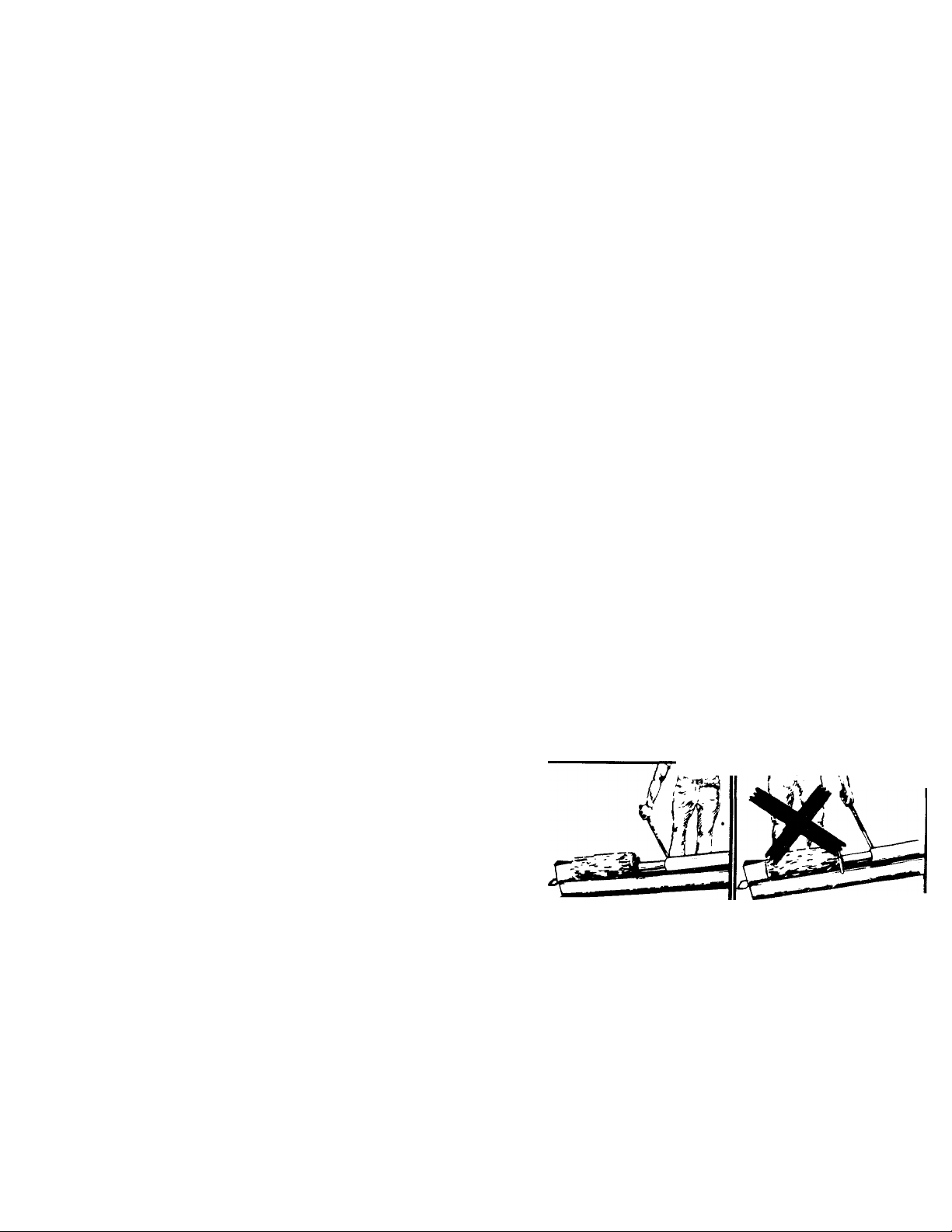
1. Stand behind the ram when operating. See
illustrations.
T
PREPARATION
1. Never wear loose clothing or jewelry that can
be caught by moving parts of your log splitter
and pull you into it. Keep clothing away from all
moving parts of your log splitter.
2. Wear proper head gear to keep hair away from
moving parts. Always wear protective hearing
devices as needed.
3. Always wear safety shoes. A dropped log can
seriously injure your foot.
4. Always wear safety glasses or goggles while
operating your splitter. A piece of splitting log
could fly off and hit your eyes.
o. If you wear gloves, be sure they are tight fitting
without loose cuffs or draw strings.
6. Use your log splitter in daylight, or under good
artificial light.
CO RR E CT
2. Know how to stop the unit and disengage the
controls.
3. Never place hands or feet between log and split
ting wedge or between log and ram during
forward or reverse stroke. To do so may result
in crushed or amputated fingers or toes, or
worse, you may lose an arm or foot.
4. Do not straddle the splitter when using it. A slip
in any position could result in a serious injury.
5. Do not step over your log splitter when the
engine is running. You may trip or accidentally
activate the ram if your step over. If you need
to get to the other side, walk around.
6. Never try to split two logs on top of each other.
One may fly out and injure you.
never!
Page 4

7. When loading the log splitter, place your hands
on the side of the log, not at the ends. Nevar
attempt to load your splitter while the ram is in
motion. You may get caught by the ram and
injured.
8. Only use your hand to operate the ram ar
control lever. Never use your foot or a rope ar
any other extension device. This could result in
your inability to stop your splitter quickly enoui|h
and cause an injury.
9. Always keep fingers away from any cracks that
open in the log during splitting operation. Th 3y
can quickly close and pinch or amputate your
fingers.
10. Never attempt to split wood across the grain.
Some types of wood may burst or fly out of your
splitter and result in injury to you or a bystander.
11. For logs that are not cut square, the longest
portion of the log should be rotated down and
the most square end placed against the ram.
12. Keep your work area clean. Immediately remo/e
split wood around your splitter so that you do
not stumble over it.
13. Never move the log splitter while the engine is
running.
14. Never leave your log splitter unattended with tne
engine running. Shut off the engine if you c re
leaving your splitter, even for a short period of
time. Someone could accidentally activate tne
ram and be injured.
15. Do not run engine in an enclosed area. Exhai st
gases contain carbon monoxide. This odorless
gas can be deadly when inhaled.
16. Be careful not to touch the muffler after tne
engine has been running as it is HOT.
17. If the equipment should start to vibr< te
abnormally, stop the engine and check im
mediately for the cause. Vibration is generelly
a warning of trouble
18. When cleaning, repairing or inspecting, meke
certain all moving parts have stopped.
Disconnect the spark plug wire, and keep the
wire away from the plug to prevent accidental
starting.
MAINTENANCE AND STORAGE
1. Do not operate your splitter in poor mechani :al
condition or when in need of repair.
2. Periodically check that all nuts, bolts, screvt/s,
hose clamps and hydraulic fittings are tight to
be sure equipment is in safe working condition.
Where appropriate, check all safety guards e nd
shields, to be sure they are in the proper
position. Never operate your splitter with sefety guards, shields or other protective featu 'es
removed. These safety devices are for your
protection.
3. Replace all damaged or worn parts such as
hydraulic hoses and fittings immediately with
manufacturer approved replacement parts.
4. Do not change the engine governor settingj or
overspeed the engine. This increases the hazard
of personal injury. The maximum engine speied
is preset by the manufacturer and is within s£ fe-
ty limits.
5. Do not alter your splitter in any manner such
as attaching a rope or extension to the control
lever or adding to the width or height of the
wedge. Such alterations may cause your split
ter to be unsafe.
6. Perform all recommended maintenance pro
cedures before you use your splitter.
7. Do not service or repair your log splitter without
disconnecting the spark plug wire.
8. Never store the equipment with gasoline in the
tank inside of a building where ignition sources
are present, such as hot water and space
heaters, clothes dryers and the like. Allow the
engine to cool before storing in any enclosure.
9. Always store gasoline in an approved, tightly
sealed container. Store the container in a cool,
dry place. Do not store in a building where
ignition sources are present.
10. To reduce fire hazard, keep engine free of grass,
leaves, wood chips, and excessive grease and
oil.
11. The hydraulic system of your log splitter requires
careful inspection, along with the mechanical
parts. Be sure to replace frayed, kinked, or
otherwise damaged hydraulic components.
12. Fluid escaping from a very small hole can be
almost invisible. Do not check for leaks with your
hand. Escaping fluid under pressure can have
sufficient force to penetrate skin, causing
serious personal injury. Leaks can be located by
passing a piece of cardboard or wood over the
suspected leak and looking for discoloration.
13. Should it become necessary to loosen or remove
any hydraulic fitting or line, be sure to relieve a
pressure by shutting off the engine and
moving the control handle back and forth several
times.
14. Do not remove the cap from the hydraulic tank
or reservoir while your log splitter is running. Hot
oil under pressure could cause injury.
15. The pressure relief valve on your splitter is pre
set at the factory. Do not adjust the valve. Only
a qualified service technician should perform this
adjustment.
16. Completely drain fuel tank prior to storage. This
guards against accumulation of fuel fumes
which could result in a fire hazard.
17. Never store log splitter outside without a water
proof cover. Rain will cause rust on the inside
of the cylinder.
TOWING
1. This unit should not be towed on any street,
highway or public road. Any licensing needed
to comply with the existing federal, local or state
vehicle requirements is the sole responsibility of
the purchaser.
2. Before towing, be certain the log splitter is
correctly and securely attached to the towing
vehicle, and the safety chains (if so equipped
or where required by state law) are in place.
Leave slack in chains for turning allowance.
3. Do not allow anyone to sit or ride on you
splitter. They can easily fall off and be serious
ly injured.
Page 5
TOOLS REQUIRED:
Raw Hide or Plastic Hammer
1-1/8", 3/4" 9/16", 1/2" and 7/16" Wrench (or one
Adjustable Wrench)
£^^r of Pliers
Additional Adjustable Wrench
o THER MATERIALS NEEDED:
Approximately 2-1/2 gallons of Dexron II auto
matic transmission fluid (may be obtained at your
local service station or auto parts store).
Funnel
Engine oil and gasoline (refer to separate engine
manual).
-
----
® @) @
" T
MN-
FIGURE 1
ASSEMBLY INSTRUCTIONS
NOTE
This unit is shipped WITHOUT GAS
OLINE or OIL. After assembly, see
separate engine manual for proper
fuel and engine oil recommendations.
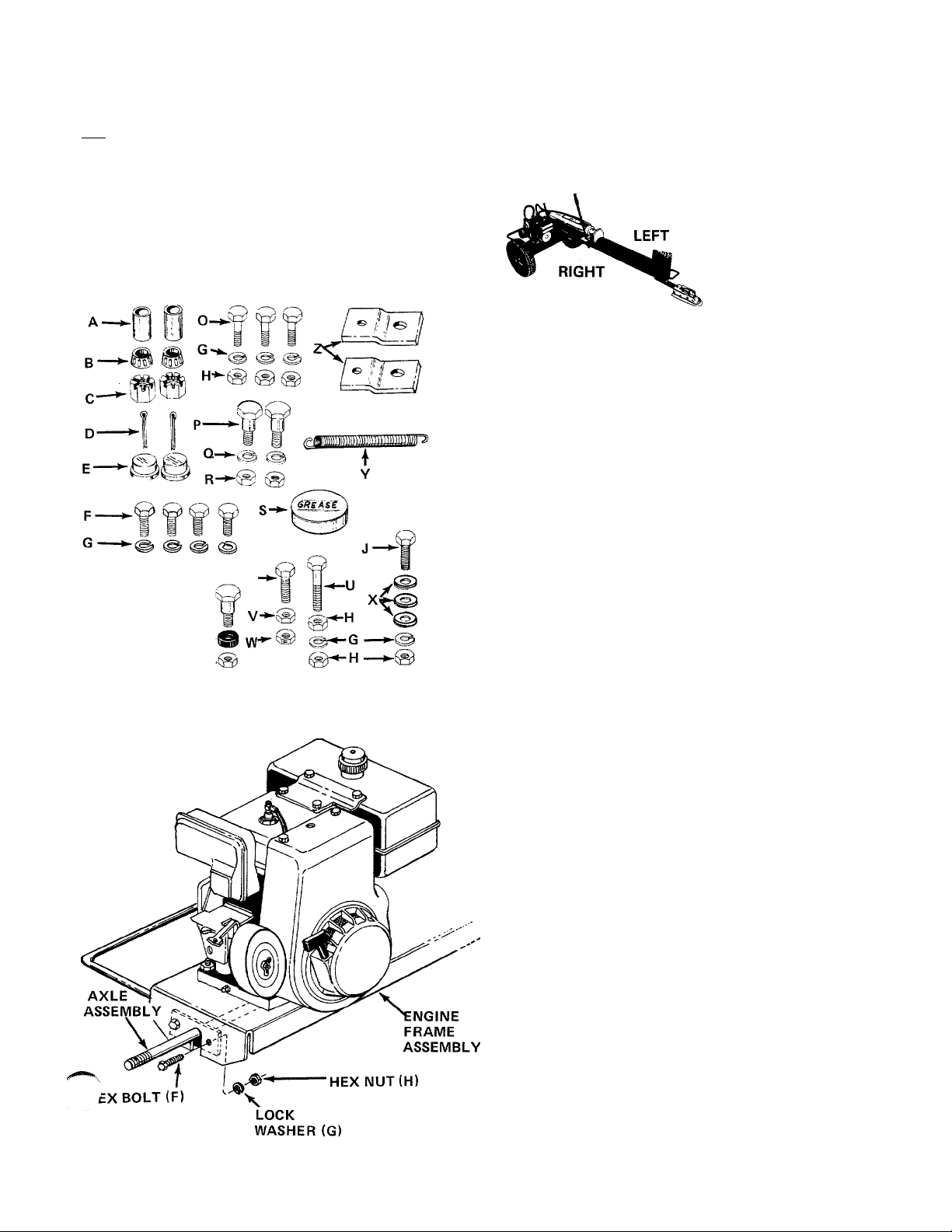
NOTE
Reference to right or left hand
side of the unit is determined
from the operating position,
facing forward. See illustration
at left.
CONTENTS OF HARDWARE PACK (See Figure 1):
A (2) Spacers 1-1/2" Long
B (2) Tapered Roller Bearings
C (2) Castle Nuts 3/4-16 Thread
D (2) Cotter Pins
E (2) Hub Caps
F (4) Hex Bolts 3/8-24 x 1" Long
G (9) Lock Washers 3/8" I.D.
H (10) Hex Nuts 3/8-24 Thread
J (1) Hex Bolt 3/8-24 X 1-1/4" Long
K (1) Hex Lock Nut 5/16-18 Thread
L (1) Shoulder Bolt
M (1) Rubber Washer
N (1) Hex Lock Nut 3/8-16 Thread
0 (3) Hex Bolts 3/8-24 x 3/4" Long
P (2) Shoulder Bolts
Q (2) Lock Washers 5/16" I.D.
R (2) Hex Nuts 5/16-18 Thread
S (1) Automotive Grease
T (1) Hex Bolt 1/4-28 X 1" Long
U (1) Hex Bolt 3/8-24 X 1-3/4" Long
V (1) Hex Nut 1/4-28 Thread
W (1) Hex Lock Nut 1/4-28 Thread
X (3) Flat Washers
Y (1) Spring
Z (2) Pivot Brackets
FIGURE 2
LOOSE PARTS IN CARTON:
(1) Axle Assembly
(2) Wheels
(2) Tow Hitch Brackets
(1) Tow H itch Assembly
(1) Pivot Stand
(1) Hitch Chain
(1) Engagement Rod Assembly
(1) Engagement Handle
Remove log splitter and loose parts from carton. Make
certain all parts and literature have been removed
from the carton before the carton is discarded.
INSTALLATION OF WHEELS
1. Place the axle assembly in position inside the
the engine frame assembly as shown in figure 2.
Secure with hex bolts (F), lock washers (G) and
hex nuts (H).
2. Remove the protective plastic covers from the ends
of the axles.
Page 6

HUBCAP
TAPERED (A)
ROLLER
BEARING (B)
HUB
CAP (E)
TAPERED
BEARING
(TAPER TO
INSIDE
SPACER
AXLE
3.
Pack the tapered roller bearings (B) with auto
motive grease provided.
NOTE
Do not put any grease in the hub caps.»
Place one spacer (A) on the axle, then one wheel
and a tapered roller bearing (B). See figure 3.
Thread hex castle nut (C) on axle. Tighten castle
nut until snug, then back off approximately 1/3
turn or until one of the slots on the castle nut
lines up with hole in axle. Secure castle nut to
axle with cotter pin (D). See figure 3.
COTTER
FIGURE 3
HEX NUTS^
FIGURE 4
^1
HEX CASTLE
NUT (C)
\
LOCK
WASHER
PIVOT
BRACKET (Z)
LOCK
3-1/2" LONG
HEX BOLTS
braci:et(z)
• TOW HITCH
BRACKETS
NOTE
Make certain wheel bearings were
packed with grease.
Place hub cap (E) in position on wheel and tap
6.
on with a plastic hammer.
7. Repeat steps 2 through 6 for the second wheel.
ASSEMBLY OF TOW HITCH AND STAND
The wedge is already assembled to the log splitter,
and is held in place with four 3-1/2" long hex bolts,
lock washers and hex nuts. The top two bolts and
nuts are tightened securely. The bottom two bolts an''"
nuts have been assembled loosely.
Remove the two bottom bolts, lock washers and
1.
hex nuts from the beam and wedge. See figure 4.
2.
Place one tow hitch bracket on each side of the
beam, lining up the large holes in the brackets with
the bottom holes in the beam. The slots in the tow
hitch brackets face upward. Secure the tow hitch
brackets with one hex bolt, lock washer and hex
nut just removed.
Place one pivot bracket (Z) on each side of the
3.
two hitch brackets, lining up the holes in the hitch
bracket with the holes toward the end of the
beam. The pivot brackets must be assembled with
the bend to the outside as shown in figure 4. The
tab on each pivot bracket goes into the slot on
tow hitch brackets. Secure with the other hex bolt,
lock washer and hex nut removed in step 1.
Place the tow hitch assembly in position on the
tow hitch brackets. Secure the left side of tow
hitch assembly with two hex bolts (O), lock
washers (G) and hex nuts (H). See figure 5.
Secure the right hand side of tow hitch assembly
with hex bolt (O), lock washer (G) and hex nut_
(H) in the front hole only.
Thread one hex nut (H) onto hex bolt (U). Secure
rear hole in tow hitch assembly with this bolt, lock
washer (G) and another hex nut (H).
figure 5 NOTE: Spring (Y) will be attached to this bolt in step 9.
Page 7

7. Thread hex nut (V) part way onto hex bolt (T).
Secure to pivot stand with hex lock nut (W) as
shown in figure 6.
Assemble the pivot stand to the pivot brackets
with two shoulder bolts (P), lock washers (Q)
and hex nuts (R).
Attach extension spring (Y) to long hex bolts on
tow hitch and pivot stand. See figure 6.
10. Find the center link of the tow hitch chain.
Place two flat washers (X) on hex bolt (J), then
the center link on chain and another flat washer
(X). Insert bolt down through the hole in the tow
hitch assembly which is nearest the wedge. Secure
with lock washer (G) and hex nut (H). See figure
7.
CONTROL
ENGAGEMENT
HANDLE
I WARNING \
A.
Exercise extreme caution when raising
and lowering the flip stand as it is
spring loaded and could cause personal
injury.
ASSEMBLY OF ENGAGEMENT HANDLE
1. Place the flattened end of the engagement handle
down through the slotted bracket beside the beam.
Insert the end of the ferrule on the engagement
rod into the second hole from the end of the
engagement handle. See figure 8.
2. Place shoulder bolt (L) through bottom hole in
engagement handle. Place rubber washer (M) on
shoulder bolt. Secure to bracket with hex lock nut
(N). Tighten lock nut until nut is flush with the
end of the shoulder bolt.
Page 8

LOCK IMUT (K)
Secure ferrule on engagement rod to engagement
handle with hex lock nut (K). See figure 9. Tighten
lock nut until nut is flush with the end of the
ferrule.
FIGURE 9
FIGURE 10
ENGAGEME^T
HANDLE.
Place the engagement handle in reverse position,
4.
locked in the notch in the slotted bracket. See
figure 10.
Adjust the engagement rod by tightening the hex
5.
nut on the end of the rod until the plunger on the
pump is pushed all the way in when the engagemen,
handle is locked in the reverse position. Insert a
screwdriver into the slot in the plunger to keep
the rod from turning as the hex nut is tightened.
See figure 10.
FUNNEL
OPERATION
BEFORE STARTING
Fill reservoir tank on log splitter with apprc xmately 2-1/2 to 3 gallons of Dexron II automate
transmission fluid as follows. Check fluid le^el
before each use.
A. Place log splitter in the operating positon with
the beam level, using the stand provided.
B. Remove the fluid check plug from the back of
the log splitter. See figure 11. If fluid starts to
come out of the hole, fluid level is correct. If
it does not, replace the check plug loosely, p dl
the cap off the breather tube, and add Dexron
II automatic transmission fluid until fkid
starts out of the hole when the plug is remove d.
C. Replace fluid check plug securely. Replace cap
on the breather tube.
BREATHER
TUBE
FLUID
CHECK
PLUG
FIGURE 11
Page 9

NOTE
DO NOT operate log splitter without
proper amount of transmission fluid in
„_^ reservoir tank (beam).
Service engine with oil as instructed in the separate
engine manual packed with your unit.
3. Fill fuel tank, using clean, fresh, regular grade
automotive gasoline. Fill tank completely.
NOTE
Refer to engine manual packed with
log splitter for complete instructions
for the care and maintenance of engine.
READ DIRECTIONS CAREFULLY.
4. Bleed the air from the hydraulic system as follows.
a. Remove the breather cap.
b. Start the engine.
c. Slowly work the engagement handle forward
and backward until the ram moves smoothly
in both directions.
d. Stop the engine. Remove the fluid check plug,
and check fluid level as specified in step one.
Add fluid as necessary and bleed air from the
hydraulic system until oil level is correct and
the ram operates smoothly.
e. Replace breather^cap securely.
NOTE
Be certain to bFeed the air from the
hydraulic system as instructed above
after any repair work is done on the
pump, valve or cylinder, if a hose is
removed for any reason or when adding
fluid to the reservoir.
WARNING
Do not operate unit with the breather
cap removed.
TO START ENGINE
1. Place throttle control lever in FAST or CHOKE
position. See figure 12.
2. Place choke control in CHOKE position (if unit is
so equipped).
3. Grasp starter handle, place one foot on wheel and
pull starter handle with a quick, full arm stroke.
Return rope slowly to the engine.
4. After engine starts, move choke control gradually
to OFF position (if unit is so equipped). Move
throttle control to desired engine speed.
TO STOP ENGINE
1. Push shorting clip against spark plug (if unit is so
equipped) or move throttle control lever to STOP
position.
2. Disconnect spark plug wire from spark plug to
prevent accidental starting while equipment is
unattended.
USING YOUR LOG SPLITTER
WARNING
AC
This unit should not be towed on any
street, highway or public road. Any
licensing needed to comply with the
existing federal, local or state vehicle
requirements is the sole responsibility
of the purchaser. Make certain the
stand is folded up against the beam
when transporting.
Your log splitter is designed for safe, efficient
operation. BE CAREFUL TO KEEP HANDS AND
FEET AWAY FROM MOVING PARTS.
Engagement handle has three positions; (See figure 13)
Forward - ram moves toward wedge.
Neutral - ram stops in place.
Reverse - ram returns.
ENGAGEMENT HANDLE
IN NEUTRAL POSITION.
ENGAGEMENT HANDLE
HELD IN FORWARD
POSITION.
t
flH^ NOTE
A warm engine may not require
choking.
FIGURE 12 -8H.P. Briggs and Stratton engine shown
ENGAGEMENT HANDLE
LOCKED IN REVERSE
POSITION.
FIGURE 13
Maximum length that can be split is 26'
Page 10

TO OPERATE LOG SPLITTER:
1. Set throttle at maximum speed.
2. Place log on beam and hold in place with rijht
hand. See figure 14.
3. Slowly move engagement handle forward u itil
ram rests against log. Release engagement hardle
(Neutral).
4. Remove your hand from the log and step behind
the ram. See figure 15.
5. Move engagement handle forward until log is sf lit.
6. Move the engagement handle to the rear to ret jrn
ram.
WARNING {
Ai
Never attempt to cut a log in half with
the log splitter. See figure 16.
Never stand next to the ram when
operating. See figure 17. Always stand
behind the ram as shown in figure 15.
FIGURE 16
FIGURE 15
The ram should take approximately 12 seconds to
make a complete cycle. This speed may vary de
pending on throttle setting and temperature of
hydraulic fluid.
NOTE
If you lock the engagement handle in
the reverse slot, the ram will return until
it hits the engagement bracket, which will
throw the engagement handle into neutral
automatically.
FIGURE 17
MAINTENANCE
^ WARNING {
A
Always stop engine and disconnect spark
plug wire before performing any mainte
nance or adjustments.
ENGINE OIL
Change oil first two (2) hours of operation. Check
oil level every five (5) operating hours or each time
equipment is used.
Change oil every twenty-five (25) operating hours or
sooner if equipment is operated in extremely dusty
or dirty conditions.
Refer to engine manual for quantity and type of oil
ENGAGEMENT HANDLE
Periodically lubricate the area of the engagement
handle which contacts the slotted bracketon the beam,
to prevent excessive wear.
10
Page 11

LOG SPLITTER RESERVOIR FLUID
Check fluid level in log splitter reservoir before every
use. Refer to "Before Starting" under OPERATION
section.
,.-~jQhange the hydraulic fluid in the reservoir every 100
' burs of operation. Remove the six hex bolts, lock
.i/ashers and hex nuts which hold the end plate to the
beam. Remove the plate and drain the fluid. Be pre
pared to catch the fluid in a suitable container.
NOTE
Drain the fluid and flush the reservoir
tank assembly and hoses with kerosene
each time repair work is performed on
on the tank, hydraulic pump or valve.
Contaminants in the fluid will damage
the hydraulic components.
i WARNING t
END
PLATE
A
Use extreme caution when using
kerosene as it is an extremely flamm
able liquid.
HOSE CLAMPS
Check the hose clamps on the bottom of the pump
for proper tightness before each use. Hose clamps on
return hose should be checked once a season.
CARBURETOR ADJUSTMENTS
\ WARNING {
A
If any adjustments are made to the
engine while the engine is running
(e.g. carburetor), keep clear of all
moving parts. Be careful of heated
surfaces and muffler.
Refer to engine manual packed with your unit for
carburetor adjustment information.
TIRE PRESSURE
Check sidewall of tire for manufacturer's maximum
tire pressure. If this information does not appear on
your tire, maximum tire pressure under any circum
stances is 30 p.s.i. Equal tire pressure should be
maintained on all tires.
INSTALLATION OF TIRE TO RIM
HEX BOLTS
LOCK WASHERS
HEX NUTS
figure 18
When the hydraulic fluid is drained from the reservoir,
clean the strainer tube assembly as follows.
1. Remove the hose clamp at the inlet hose {bottom
hose). See figure 18.
2. Pull the inlet hose off the fitting at the beam.
Using an adjustable wrench, remove the fitting
from the beam.
3. Reach inside the end of the beam and pull out the
strainer tube assembly. See reference number 96
on page 12.
4. Clean the strainer tube assembly with kerosene,
and reassemble in reverse order.
eassemble the end plate. Refill reservoir with
approximately 2-1/2 to 3 gallons of Dexron II auto
matic transmission fluid and bleed the air from the
hydraulic system as instructed in "Before Starting"
under OPERATION section.
A
The following procedure must be
followed when removing or installing
a tire to the rim.
1.
Be sure rim is clean and rust free.
2.
Lubricate both the tire and rim generously.
3.
Never inflate to over 30 p.s.i. to seat beads.
Excessive inflation pressure when seating beads
may cause tire/rim assembly to burst with force
sufficient to cause serious injury.
J WARNING I
OFF-SEASON STORAGE
If the machine is to be inoperative for a period
longer than 30 days, prepare for storage as follows.
1. Clean the engine and the entire unit thoroughly.
2. Wipe the entire machine with an oiled rag to
protect the surfaces.
3. Refer to the engine manual for correct engine
storage instructions. The engine must be
completely drained of fuel to prevent gum
deposits from forming on essential carburetor
parts, fuel lines and fuel tanks.
4. Store unit in a clean, dry area.
NOTE
When storing any type of power
equipment in an unventilated or
metal storage shed, care should be
taken to rust proof the equipment.
Using a light oil or silicone, coat the
equipment, especially all moving parts.
11
Page 12

Models 642 and 64i5
NOTE; The engine is not under warranty by
the log splitter manufacturer ... If repairs or
service is needed on the engine, please contact
your nearest authorized engine service outlet.
Check the "Yellow Pages” of your telephone
book under" Engines — Gasoline".
*The hydraulic pump is one of two type;. As complete units, the two pumps are interchangeable
(refer to parts list for part number). If it is necessary to determine the specific type of pump
on your unit, refer to the illustrations below.
Find It Fa: t
In The
Yellow Paces
'3bfVft.K)£lS pDifi^P iIks WolbeD Ih) AnAPTF/C
F€NH£.IL StoHE i^EEDS Ati^rTCiL 737 'D 19 /
NOTE
This instruction manual covers various models and all
specifications shown do not necessarily apply to your
model. Specifications subject to change without notice
or obligation.
12
Page 13

Models 642 and 645
PARTS LIST FOR MODELS 642 AND 645 LOG SPLITTERS
"S
EF.
r^lO.
PART
NO.
COLOR
CODE
DESCRIPTION
NEW
PART
REF.
NO.
PART
NO.
COLOR
CODE
DESCRIPTION
NEW
PART
1 710-0118 Hex Bolt 5/16-18 X .75" 35
Lg.*
2
3
4
5
6
7
8
9
10
11
12
13
14 13295
15
16
18
19
20
21 717-0460
24
26
27
28
29
30
31
1 32
33
34
710-0168 Hex Bolt 3/8-16 X ,50"Lg.*
712-0267
717-0407 Control Valve 400 37 738-0601 Shoulder Bolt. .62" Dia. x
726-0132 Hose Clamp 5/8"
727-0297 High Pressure Hose Ass'y.
727-0299 Return Hose - Valve to
736-0119 L-Wash. 5/16" I.D.*
736-0169
737-0153 Return Elbow
737-0171 90° Solid Male Adapter
737-0192 90° Solid Male Adapter
781-0035 Valve Mtg. Plate 46
719-0278
719-0277 Coupling Shield (645) 49
710-0117 Hex Bolt 5/16-24 x 1.00"
710-0157 Hex Bolt 5/16-24 x .75"
710-0237 Hex Bolt 5/16-24 x .62"
712-0123
714-0168
714-0172 Sq. Key 1/4" x 2.25" Lg. 55
717-0461
717-0872
717-0462
726-0132 Hose Clamp 5/8"
727-0298
781-0097
737-0192
710-0920
712-0203
717-0818
717-0817
736-0364
737-0220
Hex Nut 5/16-18 Thd.* 719-0268 Pusher Plate (645)
.38" I.D.
Tank 3/4" I.D.
L-Wash. 3/8" I.D.*
Coupling Support Brkt. 47 732-0324 Compression Spring
Ass'y. 48
Coupling Shield (642) 1.00" X .125 Thd.*
Lg*
Lg.*
Lg.
Hex Nut 5/16-24 Thd.*
Sq. Key 3/16" x 2.25" Lg. 54 710-0299 Hex Bolt 1/4-28 x 1.00"
(642)
(645)
Pump with Woodrutf Key
(642)
Pump with Woodruff Key
(645)
Flexible Coupling Comp. 58 712-0138 Hex Nut 1/4-28 Thd.
(642)
Flexible Coupling Comp.
(645)
Suction Hose 1.0" Dia.
Rear Coupling Support
Brkt.
90° Solid Male Adapter
Hex Bolt 3/4" X 4.0" Lg.
Hex Nut 3/4" Thd.
Hydraulic Cylinder 3-1/2"
Dia. (642)
Hydraulic Cylinder 4"
Dia. (645)
L-Wash. 3/4" I.D.*
High Pressure 90° Elbow
N
737-0194
36
39 15850 Flip Stand Bracket
40 713-0338 Chain-Tow Hitch
41 727-0289 Tow Hitch Ass'y. Comp.
42 781-0020
43
44 13115 Ferrule Ass'y.
45
50
51 710-0106 Hex Bolt 1/4-20 x 1.75"
52 710-0191 Hex Bolt 3/8-24 x 1.25"
53
56
57 712-0117
59
60
61
62 712-0299 Hex Castle Nut 3/4-16
63 712-0375 Hex L-Nut 3/8-16 Thd.
64
65 732-0429 Extension Spring .50" O.D.
66 734-0873 Hub Cap
67 735-0144 Rubber Washer
719-0269
781-0037
712-0214
720-0157
736-0206 Special Washer .378 x
747-0484
749-0622
710-0180 Hex Bolt 3/8-24 x .75"Lg.*
710-0539 Hex Bolt 3/8-24 x 1.75"
712-0107 Hex Patch L.-Nut 1/4-20
712-0158 Hex Cent. L.-Nut 5/16-18
712-0241 Hex Nut 3/8-24 Thd.*
781-0098
714-0162 Cotter Pin 5/32" Dia. x
45° Male Adapter 3/4-16
MJ-3/8-18 NP
Pusher Plate (642)
4.75"Lg. (1/2-13 Thd.)
Stand Pivot Bracket
Tow Hitch Brk't 2 x 3/16
10.25" Lg.
Hex Cent. L.-Nut 3/8-24
Thd.
Grip-Black Vinyl
Engagement Rod 3/8" Dia.
X 9.0" Lg.
Engagement Handle
Lg.
Lg.*
Lg.*
Lg. (Grade 5)
La*
Hex Cent. L.-Nut 1/4-28
Thd.
Thd.
Front Coupling Support
Brkt.
Thd.
1.25" Lg.*
3.97" Lg.
13
Page 14

PARTS LIST FOR MODELS 642 AND 645 LOG SPLITTERS (Continued)
PART
REF.
NO.
69
70
71 738-0143
72 738-0296
73
74
75
76
77
78
79
80
81
82
83
86
COLOR
NO.
CODE
710-0363
710-0968
736-0262 Fl.-Wash. .375" I.D. x
750-0442 Spacer .75" I.D. x 1.12"
734-1016
734-0255
734-0872 Tire Only 16.0 x 4.0-2 Ply
734-1017
741-0107
781-0018
710-0152 Hex Bolt 3/8-24 x 1.0" Lg.
710-0298
710-0409
710-0442
712-0337
PART COLOR
DESCRIPTION
Hex Bolt 5/16-24 x 4.0" 87
Lg* (642) 88
Hex Bolt 5/16-24 x 5.0"
Lg.* (645) X 4.25" Lg.
.870" O.D. X .090
Shoulder Bolt .498" Dia. x O.D. X .062 Thk.
.340" Lg.
Shoulder Bolt .437" Dia. x
.268" Lg.
O.D. X 1.56" Lg.
Wheel Ass'y. Comp. 16.0 x
4.0"
Air Valve-Tubeless
Wheel Rim Ass'y. Only
Roller Rearing 3/4" I.D.
Axle Ass'y. .75" Dia. x
35.25" Lg.
Hex Bolt 5/8-18 x 3.50"
Lg.*
Hex Bolt 5/16-24 x 1.75 8 H.P. Engine (645)
Lg.*
Hex Bolt 5/16-18 X 1.50"
Lg.* 107
Hex Nut 5/1-18 Thd.*
NEW
PART
REF.
NO. CODE
NO.
712-0338 Hex Nut 11/16-12 Thd.
721-0203
89
91
92 736-0275
93
94 738-0140
95
96
97 781-0023
98
99 781-0025
100 781-0033
101
102 721-0204
103 781-0038
104
105
106
732-0352
736-0158
737-0191
745-0174
781-0021 Strainer Tube Ass'y.
781-0024
781-0036
721-0168
710-0604
721-0205
DESCRIPTION
Gasket 2.62 x 5.12
Extension Spring .50" O.D.
L-Wash. 5/8" I.D.*
Fl.-Wash. .34" I.D. x .68"
Adapter 1.0" Tube 11/16-12
"O'-Ring
Shoulder Bolt .437" Dia. x
.180" Lg.
Breather Cap
End Plate
Engagement Brk't. 1.39 x
11.75" Lg.
Complete Oil Tank Ass'y.
Engine Frame Ass'y.
Filler Tube Ass'y.
"O'-Ring 92" I.D. x 1.16"
O.D. X .116 Dia.
Wedge Ass'y.
5 H.P. Engine (642)
Bearing Seal
Hex Hd. Tap Scr. 5/16"
Gasket
NEW
PART
*For faster service order standard nuts, bolts, and washers locally. If these items cannot be obtained locally, order by part number and
size as shown on parts list.
Models 642 and 645
П2
PARTS LIST FOR MODEL 645
PART NO. DESCRIPTION
NEW^
PART
REF.
NO.
PARTS LIST FOR MODEL 642
PART NO. DESCRIPTION
NEW
PARI
REF.
NO.
12717-0818
753-0272
Cylinder Ass'y- Comp.
3-1/2" Cyl. Kit "0"-Ring Se :
12717-0817
14
753-0273
Cylinder Ass'y. Comp
4" Cyl. Kit "0"-Ring Set
Page 15

TROUBLE SHOOTING CHART
SYMPTOM
Engine fails to start
2. Hard starting or loss of
power
3. Engine overheats
4. Will not split logs
5. Leaking cylinder
NOTE: For repairs beyond minor adjustments, please contact your local service dealer.
^Should be performed by an authorized service dealer only.
POSSIBLE CAUSE (S)
A. Check fuel tank for gas.
B. Spark plug lead wire
disconnected.
C. Faulty spark plug.
A. Spark plug wire loose.
B. Dirty air cleaner.
A. Carburetor not adjusted
properly.
B. Air flow restricted.
C. Engine oil level low.
A. Reservoir fluid level low.
B. Pump setting incorrect.
A. Broken seals.
B. Scored cylinder.
SOLUTION
A. Fill tank if empty.
B. Connect lead wire.
C. Clean, adjust gap or replace.
See engine manual.
A. Connect and tighten spark plug wire.
B. Clean air cleaner as described in
engine manual.
A. Adjust carburetor. See engine manual.
B. Remove blower housing and clean as
described in the engine manual.
C. Fill crankcase with the proper oil.
A. Check and fill reservoir tank as
instructed in Operation Section.
B. Adjust pump setting to 3,000 p.s.i.*
A. Replace seals.*
B. Replace cylinder.*
15
Page 16

REPLACEMENT PARTS • RO. Box 36900 • CLEVELAND OHIO 44136
 Loading...