

Page 1
OUTDOOR POWER EQUIPMENT
for all seasons
.75
5 AND 8 H.P.
LOG SPLITTERS
Important:
Read Safety Rules and
Instructions Carefully
V-
PRINTED IN U.S.A.
----------------------
Model Numbers
245-642-000
245-645-000
24642S
24645S
Thank you for purchasing
an American-built product.
-
FORM NO. 770-3966
Page 2

INDEX
Safe Operation Practices
Assembly Instructions
Operation
Maintenance
......................................
.................................
For one year from the date of orig
repair or replace, at its option, free c
part or parts found to be defective ii
the movement of any pow/er equipmi
chaser. Transportation charges for e
ty must be paid by the purchaser uni
This warranty will not apply to any (lart which has become inoperative due to misuse, ex
cessive use, accident, neglect, improper maintenance, alterations, or unless the unit has
been operated and maintained in ac ;ordance with the instructions furnished. This warran
ty does not apply tothe engine, mot( >r, battery, battery chargeror component parts thereof.
Please refer to the applicable manufacturer’s warranty on these items.
....................
............
............................... 3 Off-Season Storage ....................
............................... 5 Illustrated Parts
............................... 8 Repair Parts List..........................
............................... 10 Trouble Shooting Chart
Instructions given
are for personal
follow them.
with this symbol
safety. Be sure to
LIMITED WARRANTY
nal retail purchase, MTD PRODUCTS INC will either
f charge, F.O.B. factory or authorized service firm, any
I material or workmanship. Transportation charges for
mt unit or attachment are the responsibility of the pur-
ny parts submitted for replacement under this warraness such return is requested by MTD PRODUCTS INC.
...........................
...............
...............
...........
...........
..................15
11
12, 14
13, 14
This warranty will not apply where the unit has been used commercially.
Warranty service is available throug n your local authorized service dealer or distributor. If
you do not know the dealer or distributor in your area, please write to the Customer Service
Department of MTD.
The return of a complete unit will not be accepted by the factory unless prior written per
mission has been extended by MTC.
This warranty gives you specific letial rights. You may aiso have other rights which vary
from state to state.
AC WARNING {
This unit is equipped with an internal combustion engine and should not be used on or near any unim
proved forest-covered, brush-covered or grass-i;overed land unless the engine's exhaust system is equipped
with a spark arrester meeting applicable local or state laws (if any). If a spark arrester is used, it should be
maintained in effective working order by the o|>erator.
In the State of California the above is required by law (Section 4442 of the California Public Resources
Code). Other states may have similar laws. Fe feral laws apply on federal lands. A spark arrester muffler is
available at your nearest engine authorized service center.
Page 3
▲
IMPORTANT
It is suggested that this manual be read in its entirety before attemtping to assemble or operate. Keep this manual
a safe place for future reference and for ordering replacement parts.
nis unit is shipped WITHOUT GASOLINE or 01L. After assembly, see separate engine manual for proper fuel and
engine oil recommendations.
Your log splitter is a precision piece of power equipment, not a plaything. Therefore exercise extreme caution at all
times.
▲
TRAINING
1. Know the controls and how to stop quicklyREAD THIS OWNER'S MANUAL.
2. Do not allow children to operate. Do not allow
adults to operate it without proper instruction.
Only persons well acquainted with these rules of
safe operation should be allowed to use your log
splitter.
3. No one should operate this unit while intoxicated
or while taking medication that impairs the senses
or reactions.
4. Never use your splitter for any other purpose
than splitting wood. It is designed for this use
only and any other use may cause an injury.
5. Only the operator is to be near your log splitter
during use. Keep all others, including pets, a
minimum of 20 feet away from your work zone.
Flying wood can be hazardous.
6. Don't step over your splitter when engine is
running. You may trip or accidentally activate
ram if you step over. If you need to get to the
other side, walk around.
PREPARATION
1. Do not wear loose fitting clothing that could get
caught on the moving parts.
2. Do not operate equipment when barefoot or
wearing open sandals. Always wear safety shoes or
heavy boots. A dropped log can seriously injure
your foot.
3. Check the fuel before starting the engine. Do not
fill the gasoline tank indoors, when the engine is
running, or while the engine is still hot. Wipe off
any spilled gasoline before starting the engine.
4. Use only in daylight or in good artificial light.
5. Never operate your splitter on slippery, wet,
muddy, or icy surfaces. Safe footing is essential in
preventing accidents. Never operate your splitter
while attached to a towing vehicle.
6. Always wear safety glasses or goggles while operating your log splitter. A piece of splitting log
could fly off and hit your eyes.
7. Both ends of each log must be cut square. This
will prevent the log from flying out of the splitter
while under pressure.
SAFE OPERATION PRACTICES FOR LOG SPLITTERS
OPERATION
1. Do not change the engine governor settings or
overspeed the engine. Excessive engine speeds are
dangerous.
2. Never place hands or feet between log and split
ting wedge or between log and ram during forward
or reverse stroke. To do so may result in crushed
or amputated fingers or toes, or worse, you may
lose an arm or foot.
3. If the equipment should start to vibrate abnor
mally, stop the engine and check immediately for
the cause. Vibration is generally a warning of
trouble.
4. When cleaning, repairing or inspecting, make
certain all moving parts have stopped. Disconnect
the spark plug wire, and keep the wire away from
the plug to prevent accidental starting.
5. Handle gasoline with care. It is highly flammable.
A. Use approved gasoline container.
B. Never remove cap or add gasoline to a running
or hot engine or fill fuel tank indoors. Wipe
up spilled gasoline.
C. Don't run engine in an enclosed area. Ex
haust gases contain carbon monoxide. This
odorless gas can be deadly when inhaled.
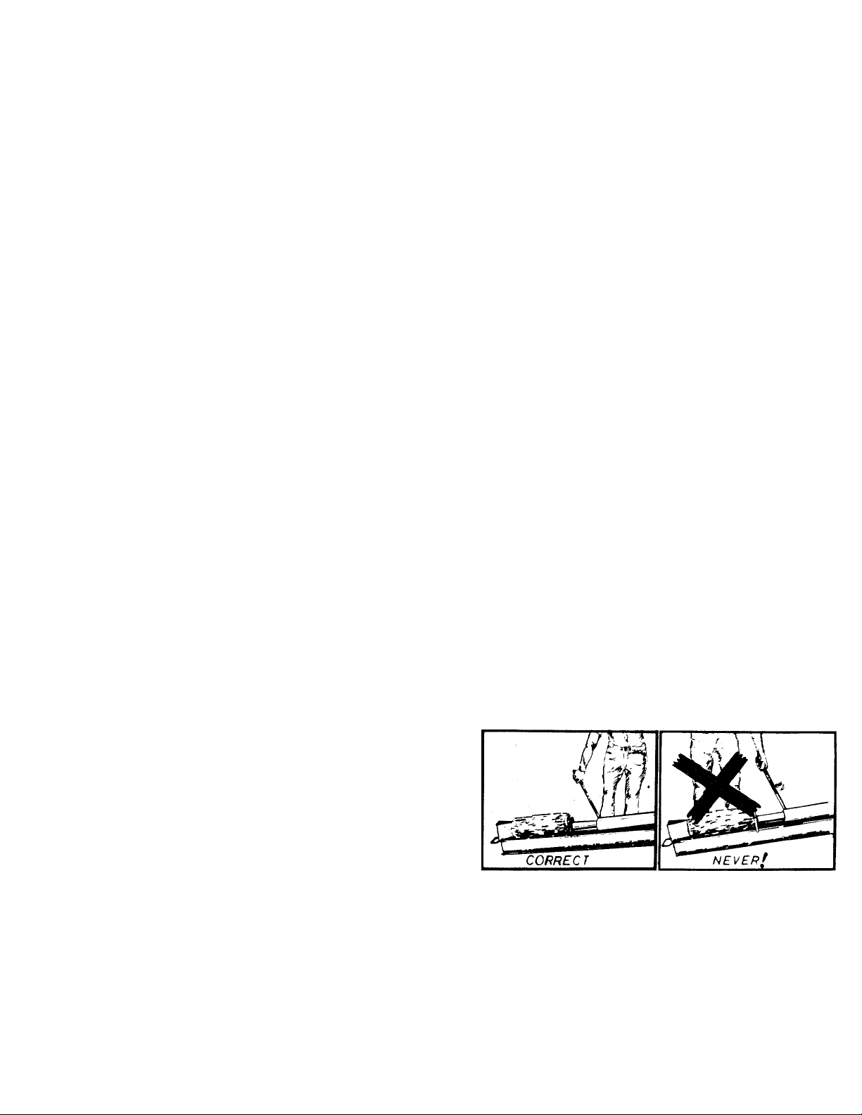
6. Stand behind the ram when operating. See draw
ings.
7.
Be careful not to touch the muffler after the
engine has been running. It is HOT.
8
Never try to split two logs on top of each other.
One may fly out and injure you.
When loading the log splitter, place your hands on
9.
the sides of the log, not at the ends.
10. For logs that are not cut square, the longest
portion of the log should be rotated down and
the most square end placed against the ram.
Page 4

11. Never attempt to split wood across the jrain.
Some types of wood may burst or fly ojt of
your splitter and result in injury to you or a
bystander.
12. Never leave your log splitter unattended wilh the
engine running. Shut off the engine if yoj are
leaving your splitter, even for a short period of
time. Someone could accidentally activât; the
ram and be injured.
13. Only use your hand to operate the ram or cc ntrol
lever. Never use your foot or a rope or any ather
extension device. This could result in your i labil
ity to stop your splitter quickly enough and
cause an injury.
14. Only operate your splitter on the level ground and
not on the side of a hill. It could tip, or railing
logs or poor footing could cause an acc dent.
This also prevents the spillage of gas from the
tank.
MAINTENANCE and STORAGE
1. Don't operate your splitter in poor mechmical
condition or when in need of repair.
2. Keep ail nuts, bolts, screws, hose clamp ; and
hydraulic fittings tight to be sure equipm;nt is
in safe working condition.
3. Replace all damaged or worn parts such cs hy
draulic hoses and fittings immediately with manu
facturer approved replacement parts.
4. Never store the equipment with gasoline in the
tank inside of a building where fumes may reach
an open flame or spark. Allow the engine to cool
before storing in any enclosure. _
5. To reduce fire hazard keep engine free of grai
leaves, wood chips, excessive grease and oil.
6. The hydraulic system of your log splitter re
quires the careful inspection along with the
mechanical parts. Be sure to replace frayed,
kinked, cracked or otherwise damaged hydraulic
components.
7. Fluid escaping from a very small hole can almost
be invisible. Do not check for leaks with your
hand. Escaping fluid under pressure can have
sufficient force to penetrate skin, causing serious
personal injury. Leaks can be located by passing
a piece of cardboard or wood over the suspected
leak and looking for discoloration.
8. Should it become necessary to loosen or remove
any hydraulic fitting or line, be sure to relieve
all pressure by shutting off the engine and moving
the control handle back and forth several times.
9. Don't remove the cap from the hydraulic tank or
reservoir while your log splitter is running. Hot
oil under pressure could cause injury.
10. Never store outside without a waterproof cover—
Rain will cause rust on the inside of the cylinder
A
CAUTION
THIS UNIT SHOULD NOT BE TOWED ON ANY
STREET, HIGHU/AY OR PUBLIC ROAD. ANY
LICENSING NELDED TO COMPLY WITH THE
EXISTING FEDLRAL, LOCAL OR STATE VEH
ICLE REQUIREMENTS IS THE SOLE RESPONSI
BILITY OF THE »URCHASER.
Page 5
TOOLS REQUIRED:
(1) Raw Hide or Plastic Hammer
(1) 1-1/8" Wrench or Adjustable Wrench
JJ) 3/4" Wrench
THER MATERIALS WEEDED:
One gallon of regular grade gasoline (for engine)
1-1/2 pints of SAE 30 or 10W-30 oil (for engine)
Approximately 2-1/2 gallons of Dexron II auto
matic transmission fluid (may be obtained at your
local service station or auto parts store.)
Funnel
[3F1
t
2
|<0))))))))))))))^MPM
Y
0
ASSEMBLY INSTRUCTIONS
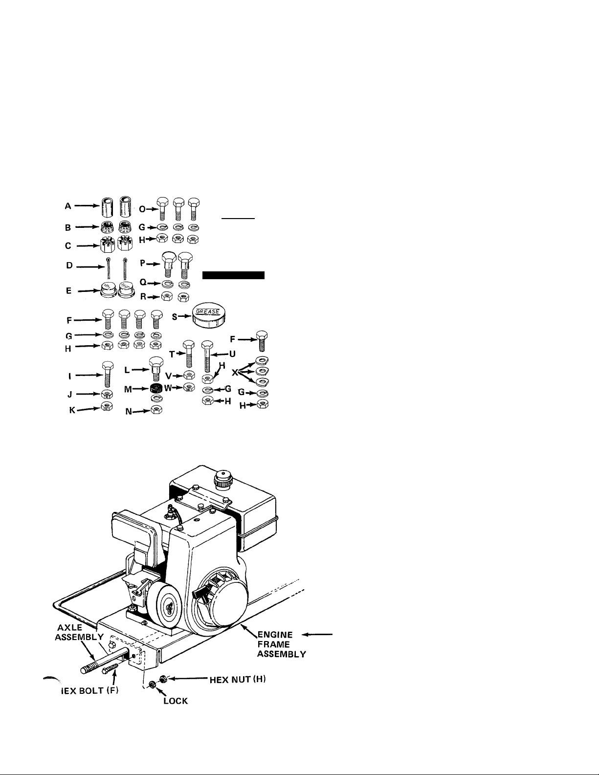
CONTENTS OF HARDWARE PACK (See Figure 1):
A (2) Spacers 1-1/2" Long
B (2) Tapered Roller Bearings
C (2) Castle Nuts 3/4-16 Thread
D (2) Cotter Pins
E (2) Hub Caps
F (5) Hex Bolts 3/8-24 X 1" Long
G (9) Lock Washers 3/8" I.D.
H (10) Hex Nuts 3/8-24 Thread
I (1) Hex Bolt 1/4-20 X 1-3/4" Long
J (1) Hex Lock Nut 1/4-20 Thread
K (1) Hex Lock Nut 5/16-18 Thread
L (1) Shoulder Bolt
M (1) Rubber Washer
N (1) Hex Nut 3/8-16 Thread
0 (3) Hex Bolts 3/8-16 x 3/4" Long
P (2) Shoulder Bolts
Q (2) Lock Washers 5/16" I.D.
R (2) Hex Nuts 5/16-18 Thread
S (1) Automotive Grease
T (1) Hex Bolt 1/4-28 X 1" Long
U (1) Hex Bolt 3/8-24 x 1-3/4" Long
V (1) Hex Nut 1/4-28 Thread
W (1) Hex Lock Nut 1/4-28 Thread
X (3) Flat Washers (Special)
Y (1) Spring
Z (2) Pivot Brackets
FIGURE 1
LOOSE PARTS IN CARTON:
(1) Axle Assembly
(2) Wheels
(2) Tow Hitch Brackets
(1) Tow Hitch Assembly
(1) Pivot Stand
(1) Hitch Chain
(1) Engagement Rod Assembly
(1) Engagement Handle
Remove log splitter and loose parts from carton. Make
certain all parts and literature have been removed
from the carton before the carton is discarded.
INSTALLATION OF WHEELS
1. Place the axle assembly in position inside the
the engine frame assembly as shown in figure 2.
Secure with hex bolts (F), lock washers (G) and
hex nuts (H).
FIGURE 2
WASHER (G)
Page 6

HUBCAP
TAPERED (A)
ROLLER _
BEARING (B)
HUB
CAP (E)
TAPERED
BEARING
(TAPER TO
INSIDE)
SPACER
2. Pack the tapered roller bearings (B) with auto
motive grease provided.
NOTE
Do not put any grease in the hub caps.
Place one spacer (A) on the axle, then one wheel
and a tapered roller bearing (B). See figure 3.
Thread hex castle nut (C) on axle. Tighten castle
nut until snug, then back off approximately 1/3
turn or until one of the slots on the castle nut
lines up with hole in axle. Secure castle nut to
axle with cotter pin (D). See figure 3.
NOTE
COTTER
FIGURE 3
FIGURE 4
FIGURE 5
HEX^
nut\
HEX CASTLE
NUT (C)
PIVOT
BRACKET (Z)
LOCK
3-1/2" LO MG
HEX BOLTS
PIVOT
BRACKET (Z)
TOW HITCH
BRACKETS
Make certain wheel bearings were
packed with grease.
5. Place hub cap (E) in position on wheel and tap
on with a plastic hammer.
6. Repeat steps 3 through 6 for the second wheel.
ASSEMBLY OF TOW HITCH AND STAND
The wedge is already assembled to the log splitter,
and is held in place with four 3-1/2" long hex bolts,
lock washers and hex nuts. The top two bolts and.,
nuts are tightened securely. The bottom two bolts a'
nuts have been assembled loosely.
1. Remove the two bottom bolts, lock washers and
—■ hex nuts from the beam and wedge. See figure 4.
2. Place one tow hitch bracket on each side of the
beam, lining up the large holes in the brackets
with the bottom holes in the beam. Secure the
tow hitch brackets with one hex bolt, lock washer
and hex nut just removed.
3. Place one pivot bracket (Z) on each side of the
two hitch brackets, lining up the holes in the
hitch bracket with the holes toward the end of the
beam. The pivot brackets must be assembled with
the bend to the outside as shown in figure 4.
Secure with the other hex bolt, iock washer and
hex nut removed in step 1.
Place the tow hitch assembly in position on the
tow hitch brackets. Secure the left side of tow
hitch assembly with two hex bolts (0), lock
washers (G) and hex nuts (H). See figure 5.
Secure the right hand side of tow hitch assembly
with hex bolt (0), lock washer (G) and hex nut
(H) in the front hole only. _
Thread one hex nut (H) onto hex bolt (U). Secu
rear hole in tow hitch assembly with this bolt,
lock washer (G) and another hex nut (H).
NOTE: Spring (Y) will be attached to this bolt in step
9.
Page 7

PIVOT
BRACKET
SHOULDER
BOLT (P)
7. Thread hex nut (V) onto hex bolt (T). Secure tc
pivot stand with hex lock nut (W) as shown in
figure 6.
8. Assemble the pivot stand to the pivot brackets
with two shoulder bolts (P), lock washers (Q)
and hex nuts (R).
9. Attach extension spring (Y) to long hex bolts on
tow hitch and pivot stand. See figure 6.
EXTENSION
SPRING (Y)
HEX
BOLT (T)
FIGURE 6
CENTER LINK'
:ON CHAIN
> ^ \lock
' ^ \l PIVOT
HEX ■
NUT (V)
FLAT WASHER iX)
HEX
NUT(R)
WASHER (Q)
STAND
HEX
LOCK NUT
(W)
HEX
BOLT (F)
Find the center link of the tow hitch chain.
Place two special flat washers (X) on hex bolt (F),
then the center link on chain and another flat
washer (X). Insert bolt down through the hole in
the tow hitch assembly which is nearest the wedge.
Secure with lock washer (G) and hex nut (H).
See figure 7.
FIGURE 7
ENGAGEMENT
ASSEMBLY OF ENGAGEMENT ROD AND HANDLE
1. Attach the engagement rod assembly to the
control valve with hex bolt (I) and hex lock nut
(J) as shown in figure 8.
2.
Place the flattened end of the engagement handle
down through the slotted bracket beside the beam.
Insert the end of the ferrule on the engagement
rod into the second hole from the end of the
engagement handle. See figure 8.
3.
Place shoulder bolt (L) through bottom hole in
engagement handle. Place rubber washer (M) on
shoulder bolt. Secure to bracket with lock washer
(G) and hex nut (N).
Page 8

LOCK NUT (K)
Secure ferrule on engagement rod to engagement
handle with hex lock nut (K). See figure 9.
FIGURE 9
PLUNGER
^ ON PUMP
FIGURE 10
ENGAGEM!NT
HANDLE,
5.6.Place the engagement handle in reverse position,
locked in the notch in the slotted bracket. See
figure 10.
Adjust the engagement rod by tightening the hex
nut on the end of the rod until the plunger on thi
pump is pushed all the way in when the engagement
handle is locked in the reverse position. Insert a
screwdriver into the slot in the plunger to keep
the rod from turning as the hex nut is tightened.
See figure 10.
FUNNEL
OPERATION
BEFORE STARTING
1. Fill reservoir tank on log splitter with approxmately 2-1/2 to 3 gallons of Dexron II automatic
transmission fluid as follows. Check oil level befc re
each use.
A. Place log splitter in the operating position w th
the beam level, using the stand provided.
B. Remove the oil check plug.from the back of
the log splitter. See figure 11. If oil starts to
come out of the hole, oil level is correct, k it
does not, remove the cap from the breatier
tube and add oil until oil starts out of lhe
check hole.
C. Replace oil check plug. Replace cap on lhe
breather tube.
BREATHER
TUBE
OIL
CHECK
PLUG
FIGURE 11
Page 9

NOTE
DO NOT operate log splitter without
proper amount of oil in reservoir tank
(beam).
2. Fill sump with oil as instructed in the separate
engine manual packed with your unit.
3. Fill fuel tank, using clean, fresh, regular grade
automotive gasoline. Fill tank completely.
NOTE
Refer to engine manual packed with
log splitter for complete instructions
for the care and maintenance of en
gine. READ DIRECTIONS CARE
FULLY.
TO START ENGINE
1. Place throttle control lever in FAST or CHOKE
position. See figure 12.
2. Place choke control in CHOKE position (if unit
is so equipped).
NOTE
A warm engine may not require
choking.
3. Grasp starter handle, place one foot on wheel and
pull starter handle with a quick, full arm stroke.
Return rope slowly to the engine.
4. After engine starts, move choke control gradually
to OFF position (if unit is so equipped). Move
throttle control to desired engine speed.
TO STOP ENGINE
1. Move throttle control lever to STOP position.
2. Disconnect spark plug wire from spark plug to
prevent accidental starting while equipment is
unattended.
USING YOUR LOG SPLITTER
WARNING
áki
This unit should not be towed on any
street, highway or public road. Any
licensing needed to comply with the
existing federal, local or state vehicle
requirements is the sole responsibility
of the purchaser. Make certain the
stand is folded up against the beam
when transporting.
Your log splitter is designed for safe, efficient
operation. BE CAREFUL TO KEEP HANDS AND
FEET AWAY FROM MOVING PARTS.
Engagement handle has three positions: (See figure 13)
Forward - ram moves toward wedge.
Neutral - ram stops in place.
Reverse - ram returns.
t
FIGURE 12A - 5 H.P. Tecumseh engine shown
ENGAGEMENT HANDLE
IN NEUTRAL POSITION.
ENGAGEMENT HANDLE
LOCKED IN REVERSE
POSITION.
FIGURE 13
ENGAGEMENT HANDLE
HELD IN FORWARD
POSITION.
-r'-X'i
Maximum length that can be split is 26".
Page 10

TO OPERATE LOG SPLITTER:
1. Set throttle at maximum speed.
2. Place log on beam and hold in place with right
hand. See figure 14.
3. Slowly move engagement handle forward until
ram rests against log. Release engagement bundle
(Neutral).
4. Remove your hand from the log and step b( hind
the ram. See figure 15.
5. Move engagement handle forward until log is split.
6. Move the engagement handle to the rear to ruturn
ram.
AC warnIng^}
Never attempt to cut a log in half with the
log splitter. See figure 16.
Never stand next to the ram when
operating. Always stand behind the ram.
See figure 17.
FIGURE 16
FIGURE 15
The ram should take approximately 12 seconds to
make a complete cycle. This speed may varv de
pending on throttle setting and temperature of oi .
NOTE
If you lock the engagement handle in
the reverse slot, the ram will return until
it hits the engagement bracket, which will
throw the engagement handle into neutral
automatically.
FIGURE 17
MAINTENANCE
J* waVning^I
Always stop engine and disconnect spark
plug wire before performing any mainte
nance or adjustments.
ENGINE OIL
Change oil first two (2) hours of operation. Check
oil level every five (5) operating hours or each tinr«’equipment is used.
Change oil every twenty-five (25) operating hours or
sooner if equipment is operated in extremely dusty
or dirty conditions.
Refer to engine manual for quantity and type of oil.
10
A
Page 11

LOG SPLITTER RESERVOIR OIL
Check oil in log splitter reservoir before every use.
Refer to "Before Starting" under OPERATION
^ection.
hange the oil in the reservoir every 100 hours of
operation. Remove the six hex bolts, lock washers
and hex nuts which hold the end plate to the beam.
Remove the plate and drain the oil. Be prepared to
catch oil in a suitable container.
NOTE
Drain the oil and flush the reservoir
tank assembly and hoses each time
repair work is performed on the tank,
hydraulic pump or valve. Contaminants
in the oil will damage the hydraulic
components.
END
PLATE
CARBURETOR ADJUSTMENTS
A
If any adjustments are made to the
engine while the engine is running
(e.g. carburetor), keep clear of all
moving parts. Be careful of heated
surfaces and muffler.
Refer to engine manual packed with your unit for
carburetor adjustment information.
TIRE PRESSURE
Check sidewall of tire for manufacturer's max
imum tire pressure. If this information does not
appear on your tire, maximum tire pressure under
any circumstances is 30 p.s.i. Equal tire pressure
should be maintained on all tires.
INSTALLATION OF TIRE TO RIM
^ yVARNING (
HEX BOLTS
LOCK WASHERS
HEX NUTS
FIGURE 18
When the oil is drained from the reservoir, clean the
strainer tube assembly as shown.
1. Remove the hose clamp at the inlet hose (bottom
hose). See figure 18.
2. Pull the inlet hose off the fitting at the beam.
Using an adjustable wrench, remove the fitting
from the beam.
3. Reach inside the end of the beam and pull out the
strainer tube assembly.
4. Clean the strainer tube assembly and reassemble in
reverse order.
Reassemble the end plate. Refill oil reservoir with
approximately 2-1/2 to 3 gallons of Dexron II
automatic tarnsmission fluid as instructed in "Before
Starting" under OPERATION section.
*^SE CLAMPS
..,neck the hose clamps on the bottom of the pump
for proper tightness before each use.
Hose clamps on the return hose should be checked
once a season.
A
The following procedure must be
followed when removing or install
ing a tire to the rim.
1. Be sure rim is clean and rust free.
2. Lubricate both the tire and rim generously.
3. Never inflate to over 30 p.s.i. to seat beads.
Excessive inflation pressure when seating beads
may cause tire/rim assembly to burst with force
sufficient to cause serious injury.
{ WARNING {
OFF-SEASON STORAGE
If the machine is to be inoperative for a period
longer than 30 days, prepare for storage as follows.
1. Clean the engine and the entire unit thoroughly.
2. Wipe the entire machine with an oiled rag to
protect the surfaces.
3. Refer to the engine manual for correct engine
storage instructions. The engine must be
completely drained of fuel to prevent gum
deposits from forming on essential carburetor
parts, fuel lines and fuel tanks.
4. Store unit in a clean, dry area.
NOTE
When storing any type of power
equipment in an unventilated or
metal storage shed, care should be
taken to rust proof the equipment.
Using a light oil or silicone, coat the
equipment, especially all moving parts.
11
Page 12

Models 642 and 645
If YOU WRITE TO US ABOUT THIS ARTICLE
OR IF YOU ORDER REPLACEMENT PARTS AL
WAYS MENTION THIS MODEL & SERIAL NO
MODEL
64 77
NOTE: The engine is not under warranty by
the log splitter manufacturer ... If repairs or
service is needed on the engine, please contact
your nearest authorized engine service outlet.
Check the "Yellow Pages" of your telephone
book under " Engines — Gasoline".
*The hydraulic pump is one of two tvpes. As complete units, the two pumps are interchangeable
(refer to parts list for part number). If it is necessary to determine the specific type of pump
on your unit, refer to the illustrations below.
Find It Fast
In Tl le
Yellow I’ages
NOTE
This instruction manual covers various models and all
specifications shown do not necessarily apply to your
model. Specifications subject to change without notice
or obligation.
12
Page 13

Models 642 and 645
PARTS LIST FOR MODELS 642 AND 645 LOG SPLITTERS
Sef.
Л10.
1
PART
NO.
710-0118
2 710-0168
712-0267
3
717-0407
4
726-0132 Hose Clamp 5/8"
5
727-0297
6
727-0299 Return Hose - Valve to Tank
7
736-0119 L.-Wash. 5/16" I.D.*
8
736-0169 L.-Wash. 3/8" I.D.*
9
10
11
12
13
737-0153 Return Elbow
737-0171 90° Solid Male Adapter Lg.*
737-0192
781-0035
14
15 14806
710-0117
16
710-0157 Hex Bolt 5/16-24 x .75"
17
18
710-0653
19 712-0123
20 714-0172
21
22 735-0205
23
24 717-0479 Coupling Half 1.00" I.D.
25 717-0498
26
27
28
29 737-0192
30 710-0920
31 712-0203
32 717-0818
33
34
35
36 719-0269
37
Ì39
40
41
42 781-0020
43
COLOR
CODE
DESCRIPTION
Hex Bolt 5/16-18 X .75"
Lg.*
Hex Bolt 3/8-16 X.60" Lg.*
Hex Nut 5/16-18 Thd.*
Control Valve 400
High Pressure Hose Ass'y-
.38" I.D.
3/4" I.D.
90° Solid Male Adapter
Valve Mtg. Plate
13295
Coupling Support Brkt.
Ass'y.
Coupling Shield
Hex Bolt 5/16-24 X 1.00"
Lg.*
Lg.*
Hex Wash. Hd. Tap Scr. 58
1/4-20 X .38" Lg.
Hex Nut 5/16-24 Thd.*
Sq. Key 1/4" x 1/4" x 2.25
Lg.
717-0460 Pump with Woodruff Key
(642)
717-0461
Pump with Woodruff Key (645)
Spider L-0-90
710-0419 Set Scr. 1/4-20 X .25" Cup
Coupling Half .50" I.D.
726-0132 Hose Clamp 5/8" 66
727-0298 Suction Hose 1.0" Dia.
736-0119 L.-Wash. 5/16" I.D.*
90° Solid Male Adapter N
Hex Bolt 3/4" X 4.0" Lg. 70
Hex Nut 3/4" Thd.*
Hydraulic Cylinder 3-1/2"
Dia. (642)
717-0817
Hydraulic Cylinder 4"
Dia. (645)
736-0364 L.-Wash. 3/4" I.D.*
737-ea>52<52^
High Pressure 90° Elbow X 1.56" Lg.
737-0194 45° Male Adapter 3/4-16 MJ
3/8-18 NP
Pusher Plate (642) N
719-0268
738-0601
Pusher Plate (645)
Shoulder Bolt .62" Dia. x
4.75" Lg. (1/2-13 Thd.)
15850
713-0338
Flip Stand Bracket
Chain-Tow Hitch
727-0289 Tow Hitch Ass'y. Comp. N
Stand Pivot Bracket N
781-0037
Tow Hitch Brk't. 2 x 3/16 x 81
10.25" Lg.
NEW
PART
N 49
N
N
1
N 67
-
N
N 76
N 78
N
REF.
PART
NO.
NO.
44 13115
712-0214 Hex Cent. L.-Nut 3/8-24
45
COLOR
CODE
DESCRIPTION
Ferrule Ass'y.
Thd.
720-0157
46
732-0324 Compression Spring
47
48 736-0206
Grip-Black Vinyl
Special Washer .378 x 1.00"
X .125 Thd.*
747-0484 Engagement Rod 3/8' Dia. x
9.0" Lg.
749-0622 Engagement Handle N
50
51 710-0106
Hex Bolt 1/4-20X 1.75"
Lg.*
710-0152 Hex Bolt 3/8-24 X 1.00"
52
53 710-0180
Hex Bolt 3/8-24 x .75" Lg.*
54 710-0299 Hex Bolt 1/4-28 X 1.00"
Lg.*
710-0539 Hex Bolt 3/8-24 X 1.75" Lg.
55
(Grade 5)
712-0107 Hex Patch L.-Nut 1/4-20
.56
Lg.*
57 712-0117 Hex Cent. L.-Nut 1/4-28
Thd.
712-0138 Hex Nut 1/4-28 Thd.
59 712-0158 Hex Cent L.-Nut 5/16-18
Thd.
712-0241 Hex Nut 3/8-24 Thd.*
60
712-0267 Hex Nut 5/16-19 Thd.*
61
62 712-0299 Hex Castle Nut 3/4-16
Thd.
63 712-0798 Hex Nut 3/8-16 Thd.*
64 714-0162 Cotter Pin 5/32" Dia. x 1.25
Lg.* I
732-0429 Extension Spring .50" O.D. x
65
3.97." Lg.
734-0873
Hub Cap
735-0144 Rubber Washer
736-0119
68
L.-Wash. 5/16" I.D.*
69 736-0169 L.-Wash. 3/8" I.D.*
736-0262 Fl.-Wash. .375" I.D. x .870"
O.D. X .090
71 738-0143
Shoulder Bolt .498" Dia. x
X .340" Lg.
72 738-0296 Shoulder Bolt .437" Dia. x
.268" Lg.
750-0442
73
74
734-1016
Spacer .75" I.D. x 1.12" O.D.
Wheel Ass'y. Comp. 16.0 x
4.0"
75 734-0255 Air Valve-Tubeless
734-0872
734-1017 Wheel Rim Ass'y Only
77
Tire Only 16.0 X 4.0 -2 Ply
741-0107 Roller Rearing 3/4" I.D.
79 781-0018
Axle Ass'y. .75" Dia. x
35.25" Lg.
710-0117
80
Hex Bolt 5/16-24 X 1.00
Lg.*
710-0298
Hex Bolt 5/8-18 X 3.50"
Lg.*
NEW
PART
N
II
N
N
13
Page 14

PARTS LIST FOR MODELS 642 AND 645 LOG SPLITTERS (Continued)
REF.
PART
NO.
NO.
82
83 710-0442 Hex Bolt 5/16-18 X 1.50'
84
85 712-0267 Hex Nut 5/16-18 Thd.*
86
87 712-0338
88 721-0203
89
90 736-0119
91
92
COLOR
CODE
DESCRIPTION
710-0409 Hex Bolt 5/16-24 X 1.75
PART
NEW
REF.
NO.
94 738-0140 Shoulder Bolt .437" Dia. x
Lg.*
95 745-0174 Oil Fill Cap
96
97
712-0123
Lg.*
Hex Nut 5/16-24 Thd.*
98
712-0337
732-0352
Hex Nut 5/1-18 Thd.*
Hex Nut 11/16-12 Thd
Gasket 2.62 x 5.12
Extension Spring .50" 0, D.
x4.25" Lg.
N
N
N
99
100
101
102
L.-Wash. 5/16" I.D.*
736-0158 L.-Wash. 5/8" I.D.* 103
736-0275 Fl.-Wash. 34" I.D. x .68"
104
PART
NO.
COLOR
CODE
DESCRIPTION
.180" Lg.
781-0021
781-0023
781-0024
Strainer Tube Ass'y.
End Plate
Engagement Brk't. 1.39 x
11.75" Lg.
781-0025
Complete Oil Tank Ass'y.
781-0033 Engine Frame Ass'y.
781-0036
Filler Tube Ass'y.
721-0204 "0"-Ring 92" I.D. x 1.16"
O.D. X .116 Dia.
781-0038
Wedge Ass'y.
5 H.P. Engine (642)
NEW
PART
N
N
N
N
N
O.D. X .062 Thk. S8H.P. Engine (645)
93
*For faster service order standard nuts, bolts, and washers locally. If these items cannot be obtained locally, order by part number and
size as shown on parts list.
737-0191 Adapter 1.0" Tube 11/1(!-12 105 721-0168 Bearing Seal
"0"-Ring N 106
107
_____
_
710-0604 Hex Hd. Tap Scr. 5/16"
721-0205
Gasket
JL.
Models 642 and 645
REF.
NO.
PART NO.
12717-0818
753-0272
3-1/2" DIA. CYLINDER
PARTS LIST FOR MODEL 642
DESCRIPTION
Cylinder Ass'y. Comp.
3-1/2" Cyl. Kit "0"-Ring Snt
NEW
PARI
N
REF.
NO.
12717-0817
14
PART NO.
753-0273
4" DIA. CYLINDER
PARTS LIST FOR MODEL 645
DESCRIPTION
Cylinder Ass'y. Comp
4" Cyl. Kit "0"-Ring Set
new'
PART^
N
Page 15

TROUBLE SHOOTING CHART
SYMPTOM POSSIBLE CAUSE (S) SOLUTION
Engine fails to start A. Check fuel tank for gas.
B. Spark plug lead wire
disconnected.
C. Faulty spark plug.
2. Hard starting or loss of
power
3. Engine overheats
4. Will not split logs
5. Leaking cylinder
NOTE: For repairs beyond minor adjustments, please contact your local service dealer.
^Should be performed by an authorized service dealer only.
A. Spark plug wire loose.
B. Dirty air cleaner.
A. Carburetor not adjusted
properly.
B. Air flow restricted.
C. Engine oil level low.
A. Reservoir oil level low.
B. Pump setting incorrect.
A. Broken seals.
B. Scored cylinder.
A. Fill tank if empty.
B. Connect lead wire.
C. Spark should jump gap between
control electrode and side electrode.
If spark does not jump, replace the
spark plug.
A. Connect and tighten spark plug wire.
B. Clean air cleaner as described in
engine manual.
A. Adjust carburetor. See engine manual.
B. Remove blower housing and clean as
described in the engine manual.
C. Fill crankcase with the proper oil.
A. Check and fill oil reservoir tank as
instructed in Operation Section.
B. Adjust pump setting to 3,000 p.s.i.*
A. Replace seals.*
B. Replace cylinder.*
15
Page 16

MTD PRODUCTS INC
P.O. BOX 3690C • CLEVELAND OHIO 44136
..........................................................
YaRD-MaN CONIPANY
 Loading...