

Page 1
OWNER’S
MANUAL
5 and 8 H.P.
LOG SPLITTERS
.75
Model Numbers
242-642A
242-645A
24642-A
24645-A
important:
Read Safety Rules and
Instructions Carefully
Thank you for purchasing an
American built product.
PRINTED IN U.S.A.
FORM NO. 770-1801
Page 2

INDEX
Safe Operation Practices
Assembly Instructions ....................................................4
Operation .......................................................................5
Adjustments ...................................................................8
r
...............................................
LIMITED WARRANTY
♦
♦
♦
♦
♦
♦
♦
♦
For one year from the date of original retail purchase, MTD PRODUCTS INC will either
repair or replace, at its option, free of charge, F.O.B. factory or authorized service firm, any
part or parts found to be defective in material or workmanship. Transportation charges for
the movement of any power equipment unit or attachment are the responsibility of the pur
chaser. Transportation charges for any parts submitted for replacement under this warran
ty must be paid by the purchaser unless such return is requested by MTD PRODUCTS INC.
This warranty will not apply to any part which has become inoperative due to misuse, ex
cessive use, accident, neglect, improper maintenance, alterations, or unless the unit has
been operated and maintained in accordance with the instructions furnished. This warran
ty does not apply to the engine, motor, battery, battery chargeror component parts thereof.
Please refer to the applicable manufacturer’s warranty on these items.
3
Maintenance ................................................................. 8
Off-Season Storage
Illustrated Parts .....................................................10,
Repair Parts List
.......................................................
.....................................................
11,12
♦
♦
♦
♦
♦
♦
♦
t
♦
♦
♦
♦
This warranty will not apply where the unit has been used commercially.
Warranty service is available through your local authorized service dealer or distributor. If
you do not know the dealer or distributor in your area, please write to the Customer Service
Department of MTD.
The return of a complete unit will not be accepted by the factory unless prior written per
mission has been extended by MTD.
♦
♦
This warranty gives you specific legal rights. You may also have other rights which vary
from state to state.
V
^ WARNING I
TO PURCHASERS
OF INTERNAL COMBUSTION ENGINE EQUIPPED
MACHINERY OR DEVICES IN THE STATE OF CALIFORNIA
The equipment which you have just purchased does not have a spark arrester. If this equipment is used on
any forest covered land, brush covered land, or grass covered unimproved land in the State of California,
before using on such land, the California law requires that a spark arrester be provided. In addition, spark
arrester is required by lawn to be in effective working order. The spark arrester must be attached to the
exhaust system and comply with Section 4442 of the California Public Resources Code.
♦
♦
♦
♦
♦
♦
J
Page 3
IMPORTANT
It is suggestsd that this manual be read in its entirety before attempting to assemble or operate Keep
^ this manual in a safe place for future reference and for ordering replacement parts.
This unit is shipped WITHOUT GASOLINE or OIL. After assembly, see operating section of this manual
for proper fuel and engine oil recommendations.
Your log splitter is a precision piece of power equipment, not a plaything. Therefore exercise extreme
caution at all times.
SAFE OPERATION PRACTICES FOR LOG SPLITTERS
TRAINING
1. Know the controls and how to stop quickly-READ THE OWNER'S MANUAL.
2. Do not allow children to operate. Do not allow
adults to operate it without proper instruction.
Only persons well acquainted with these rules of
safe operation should be allowed to use your log
splitter.
PREPARATION
1. Do not wear loose fitting clothing that could get
caught on the moving parts.
2. Do not operate equipment when barefoot or wearing open Sandies. Always wear substantial foot
wear.
3. Check the fuel before starting the engine. Do not
fill the gasoline tank indoors, when the engine is
running, or while the engine is still hot. Wipe off
any spilled gasoline before starting the engine.
4. Use only in daylight or in good artificial light.
5. Never operate the equipment in the rain. Always
be sure of your footing.
OPERATION
C. Open doors if engine is run in garage-
exhaust fumes are dangerous. Do not run
engine indoors.
6. Always operate the log splitter from the engine
side of the beam.
Stand behind the ram when operating. See drawings.
Be careful not to touch the muffler after the
engine has been running. It is HOT.
1. Do not change the engine governor settings or
overspeed the engine. Excessive engine speeds are
dangerous.
2. Do not put hands or feet near rotating or moving
parts.
3. If the equipment should start to vibrate abnor
mally, stop the engine and check immediately for
the cause. Vibration is generally a warning of
trouble.
4. When cleaning, repairing or inspecting, make
certain all moving parts have stopped. Disconnect
the spark plug wire, and keep the wire away from
the plug to prevent accidental starting.
Handle gasoline with care--it is highly flammable.
A. Use approved gasoline container.
B. Never remove cap or add gasoline to a running
or hot engine or fill guel tank indoors. Wipe
up spilled gasoline.
MAINTENANCE and STORAGE
1. Keep all nuts, bolts, screws, hose clamps and
hydraulic fittings tight to be sure equipment is
in safe working condition.
2. Never store the equipment with gasoline in the
tank inside of a building where fumes may reach
an open flame of spark. Allow the engine to cool
before storing in any enclosure.
3. To reduce fire hazard keep engine free of grass,
leaves, wood chips, excessive grease and oil.
4. Do not change the engine governor settings or
overspeed the engine. Excessive engine speeds
are dangerous.
5. Never store outside without a waterproof cover.
Rain will cause rust on the inside of the cylinder.
Page 4
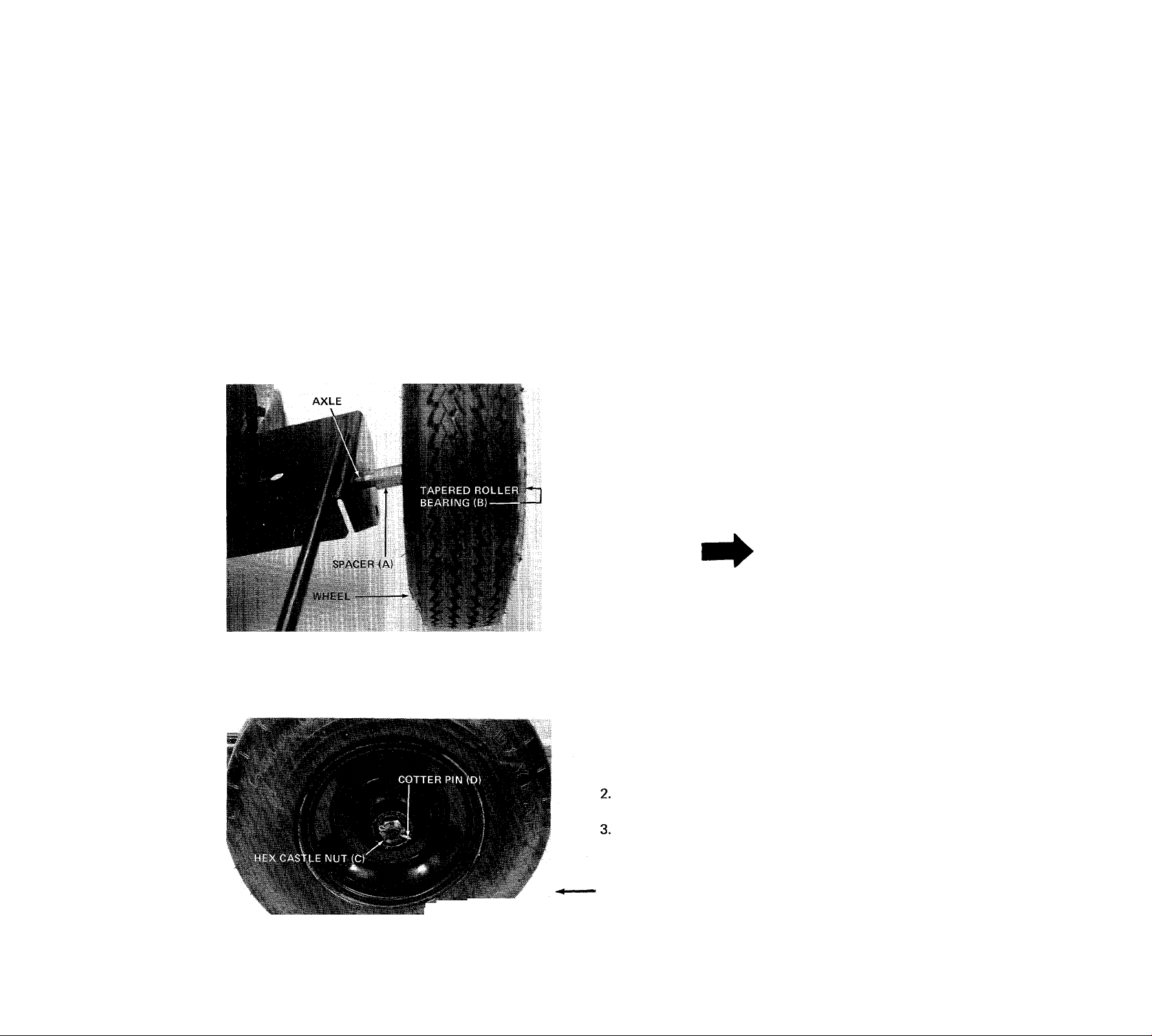
FIGURE 1
C-
D-
-ii
-F
-G
ASSEMBLY INSTRUCTIONS
TOOLS REQUIRED:
(1) Raw Hide or Plastic Hammer
(1) 1-1/8" Wrench or Adjustable Wrench
(1) 3/4" Wrench
OTHER MATERIALS NEEDED:
(A) One gallon of regular grade gasoline (for engine)
(B) 1-1/2 pints of SAE 30 or 10W-30 oil (for engine)
(C) Approximately 3 gallons of Dexron II automatic
transmission fluid. (May be obtained at your
local service station or auto parts store).
(E)
Automotive Grease
(F)
Funnel
CONTENTS OF HARDWARE PACK (See Figure 1):
(A) (2) Spacers
(B) (2) Tapered Roller Bearings
(C) (2) Hex Castle Nuts 3/4-16 Thread
(D) (2) Cotter Pins
(E) (2) Hub Caps
(F) (1) Shoulder Bolt
(G) (1) FlatWasher
FIGURE 2
1. Pack the tapered roller bearings with automotive
grease.
NOTE
Do not put any grease in the hub caps.
Place one spacer (A) on axle, then one wheel and
tapered roller bearing (B). See figure 2.
Thread hex castle nut (C) on axle. Tighten castle
nut until snug, then back off approximately 1/3
turn or until one of the slots on the castle nut lines
up with hole in axle. Secure castle nut to axle
with cotter pin (D). See figure 3.
FIGURES
Page 5

HAI'/iMER
FIGURE 4
4. Place hub cap (E) in position on wheel and tap on
with a plastic hammer. See figure 4.
5. Repeat steps 1 through 4 for the second wheel.
ENGAGEMENT ROD
FIGURES
OPERATION
BEFORE STARTING
ENGAGEMENT HANDLE
HAIR PIN COTTER
FERRULE
6. Secure engagement handle to beam with shoulder
bolt (F) and flat washer (G). See figure 5.
7. Remove the hair pin cotter from ferrule.
8. Secure engagement rod to engagement handle
with hair pin cotter. See figure 5.
TIRE PRESSURE
FOR SHIPPING PURPOSES, THE TIRES ON YOUR
UNIT MAY BE OVER-INFLATED. TIRE PRESSURE
SHOULD BE REDUCED BEFORE UNIT IS PUT
INTO OPERATION. RECOMMENDED PRESSURE
SHOULD BE APPROXIMATELY 15 P.S.I. EQUAL
TIRE PRESSURE SHOULD BE MAINTAINED ON
ALL TIRES. MAXIMUM TIRE PRESSURE IS 30
P.S.I.
NOTE
Refer to engine manual packed with
log splitter for complete instructions
for the care and maintenance of engine.
READ DIRECTIONS CAREFULLY.
1. Fill oil sump with approximately 1-1/2 pints of
SAE 30 oil, or to full mark on dipstick. See Figure
6. Use MS classification oil. Do not use oils
marked only MM or ML or unmarked. Above
32°, use SAE 30; below 32° use SAE 10W-30.
These recommendations must be followed for
\ best performance and long life.
During initial break-in period, oil level should be
watched closely. Refer to the engine manual.
2. Fill fuel tank, using clean, fresh, regular grade
automotive gasoline. Fill tank completely.
FIGURE 6
Page 6

3. Fill reservoir tank on log splitter. Remove the
the breather plug from breather tube. See figure
7. Pour approximately 3 gallons of Dexron
automatic transmission fluid ONLY into breather
tube.
VALVE IN OPEN
VALVE IN CLOSED
POSITION POSITION
1
■
DEXRON
TRANSMI
FLUID
FUNNEL
A
CAUTION
DO NOT operate log splitter without
proper amount of oil in reservoir tank
(beam).
• U- ■
BREATHER PLUG AND VALVE.
NOTE: Valve has left hand threads.
Clockwise to close.
TO STOP ENGINE
1. Move throttle control lever to STOP position.
2. Remove high tension wire from spark plug to
prevent accidental starting by children while
equipment is unattended.
USING YOUR LOG SPLITTER
Your log splitter is designed for safe, efficient
operation. CARE, OF COURSE, MUST BE EXER
CISED THAT HANDS ARE KEPT AWAY FROM
MOVING PARTS.
Engagement handle has three positions: (See figure 9)
Forward-Ram moves toward wedge.
Neutral—ram stops in place.
Reverse—ram returns.
BREATHER
TUBE- “
FIGURE?
TO START ENGINE
1. Place throttle control lever (on beam) in run
position.
2. Move choke lever to CHOKE position.
3. Open the breather valve. Valve must be open when
running log splitter. Valve must be closed when
transporting log splitter. See figure 8.
4. Grasp starter handle, place one foot on wheel and
pull starter handle with a quick, full arm stroke.
Return rope slowly to the engine.
ENGAGEMENT HANDLE
IN NEUTRAL POSITION.
ENGAGEMENT HANDLE
LOCKED IN REVERSE
POSITION.
FIGURE 8
ENGAGEMENT HANDLE
HELD IN FORWARD
POSITION.
STROKE RETURN STOP
PLUNGER.
Page 7

Maximum length that can be split is 24".
1. Set throttle at maximum speed.
2. Place log on beam and hold in place with right
hand. See figure 10.
FIGURE 10
NOTE
If you lock the engagement handle in the reverse slot,
the ram will return until it hits the return stroke stop
plunger, which will throw the engagement handle
into neutral automatically.
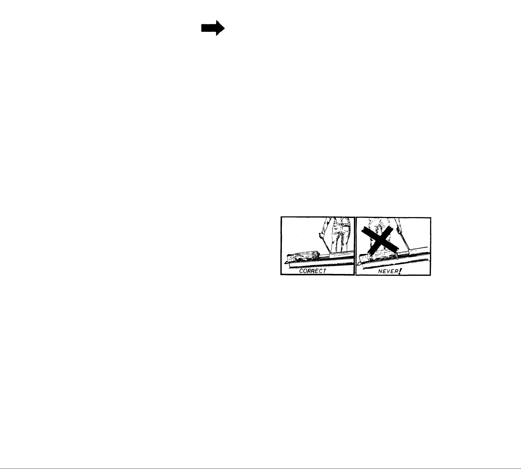
DANGER
Never attempt to cut a log in half
with the log splitter. See figure 12.
Never stand next to the ram when
operating. See figure 13. Always stand
behind the ram.
3. Slowly move engagement handle forward until
ram rests against log. Release engagement handle
(Neutral).
4. Remove your hand from the log and step behind
the ram. See figure 11.
■1 V --
FIGURE 11
FIGURE 12
5. Move engagement handle forward until log is split.
6. Move the engagement handle to the rear to return
ram.
The ram should take approximately 30 seconds to
make a complete cycle. This speed may vary
depending on throttle setting and temperature of oil.
FIGURE 13
Page 8

ADJUSTMENTS
1. Block up front of log splitter so beam is level.
CARBURETOR ADJUSTMENTS
Refer to engine manual packed with your unit for
carburetor adjustment information.
PRESSURE RELIEF VALVE SETTING
If the pressure relief valve is set too low, it will open
up before enough pressure is built up to properly
operate the ram. See figure 14.
To set the pressure relief valve:
1. Have someone place a log crossways in the splitter
and allow the ram to push against it with the
engine at full throttle.
2. If the engine begins to labor, the relief valve
setting is correct.
3. If adjustment is necessary, tighten the screw until
the engine begins to labor.
2. Remove check pipe plug in rear of beam. See
figure 15. If oil starts to come out of check pipe
plug hole, oil level is correct. IF IT DOES NC'^
add oil to breather tube (see figure 7) until o
starts out.
NOTE
Use hydraulic sealant tape or pipe
sealant on pipe plug threads.
3. Replace check pipe plug. Remove block from
under front of beam.
FIGURE 14
MAINTENANCE
t WARNING i
Always stop engine and disconnect
spark plug wire before performing any
maintenance or adjustments.
ENGINE OIL
Change oil first two (2) hours of operation and
check oil level every five (5) operating hours or each
time equipment is used.
Change oil every twenty-five (25) operating hours
or sooner if equipment is operated in extremely
dusty or dirty conditions.
Refer to engine manual for quantity and type of oil.
LOG SPLITTER RESERVOIR OIL
Check oil in log splitter reservoir before every use.
See figure 15.
^ ^ ^ ^ ^ ^ ^ ^
FIGURE 15
Change oil in the reservoir every (100) hours of
operation.
1. Remove the hose clamp at inlet hose (bottom
hose on rear of beam). See figure 16.
NOTE
Be prepared to catch oil in a suitable
container.
Pull off inlet hose from strainer tube assembly and
2.
catch oil in a suitable container. See figure 16.
With an adjustable wrench remove the strainer
3.
tube assembly. See figure 16.
NOTE
The strainer tube assembly is 53" long.
Drain oil, clean strainer tube and reassemble-
4.
using a hydraulic pipe sealant on the threads.
Remove the breather plug from breather tube.
5.
See figure 7. Pour approximately 3 gallons of
Dexron transmission fluid ONLY into breather
tube.
Page 9

INLET HOSE
HOSE CLAMP
STRAINER TUBE ASSEMBLY
INSTALLATION OF TIRE TO RIM
1. Lubricate tire beads and rim flanges.
HEX LOCKNUT
FIGURE 16
STRAINER TUBE ASSEMBLY
If the ram does not move back and forth smoothly,
the strainer tube assembly may be clogged.
To clean, follow instructions for changing the reservoir
oil, step number 1 through 3. Clean the strainer tube
assembly and reassemble using a hydraulic pipe sealant
the threads.
nOSE CLAMPS
Check the hose clamps on the bottom of the pump
for proper tightness before each use.
Hose clamps on the return hose should be checked
once a season.
lili
e
STROKE RETURN STOP PLUNGER
FIGURE 17
2. Do not exceed 30 P.S.I. when seating beads.
3. Adjust to recommended pressure after beads are
sealed.
OFF-SEASON STORAGE
In event engine is to be stored for any length of time
(30 days or more), prepare as follows:
1. Drain gasoline by tipping or by siphon hose,
then run engine until remainder is used and tank
and carburetor and empty.
HEX BOLT
STROKE RETURN STOP PLUNGER
If the engagement handle does not return to neutral
(from reverse) before the pressure relief bypass opens,
loosen the hex lock nut, and back out the hex bolt
one or two turns. See figure 17.
NOTE
When the pressure relief valve opens,
a loud high pitched sound is heard and
engine labors.
Tighten hex lock nut and operate log splitter. Repeat
if necessary.
RAM OPERATION
the ram does not move smoothly, run the ram its
.u(l stroke several times to clear out air in the system.
Be sure the breather valve is open.
If this does not correct the problem, see Strainer Tube
Assembly paragraph.
CAUTION
A
Drain into container outdoors away
from fire or flame.
Drain carburetor by running engine until it stops
2.
from lack of fuel.
Protect the inside of engine for storage by
removing spark plug and pouring one ounce of
SAE 30 oil through spark plug hole into cylinder.
Crank engine, without starting, several times to
spread oil over cylinder walls.
4.
Never store outside without a waterproof cover.
Page 10

Models 642 and 645
NOTE
This instruction manual covers various models, and
all specifications shown do not necessarily apply to
your model. Specifications subject to change without
notice or obligation.
10
Page 11

Models 642 and 645
PARTS LIST FOR LOG SPLITTER MODELS 642 and 645
Part
1
No.
717-0407
.vO.
2 727-0231
Color
Code
DESCRIPTION
Control Valve
Return Stroke High Pressure
New
Part
Hose
3 727-0211
Forward Stroke High Pressure
Hose 35
4
5
737-0161
737-0173
Breather Valve O.D. X 1.56" Lg.
Female Adapter 3/4-14 x
1/4-18 N.P.T.F.
737-0153 Return Elbow
6
726-0173 Hose Clamp 3/4" I.D.
7
8
727-0210
Return Hose 3/4" I.D. x
2.62" Lg.
9
737-0172
Nipple 1/2-14 N.P.T.F. x
1.5" Lg.
10 710-0117
Hex Bolt 5/16-24 x 1.00"
Lg. (Grade 5)
11 738-0406
12 750-0428
13 08118
14
747-0355 Cylinder Support Rod 42 736-0119 L-Wash. 5/16" I.D.*
Return Stroke Stop Plunger
Engagement Handle
Grip 41
(for 3-1/2" Dia.) (642) 43
747-0354
Cylinder Support Rod
(for 4" Dia.) (645) 44
737-0152 High Pressure 90° Elbow
5
3/8 N.P.T. X 9/16-18
16
Cylinder Assy* (See Page 12
for Breakdown)
17 736-0169
L-Wash. 3/8" I.D.*
18 712-0798 Hex Nut 3/8-16 Thd.*
15234
19
20
15235
710-0624 Hex Bolt 5/16-24 X 1.50"
21
Strainer Tube Ass'y- 48
Complete Oil Tank & Beam
Lg-
22 712-0123 Hex Nut 5/16-24 Thd.*
23 736-0159 Fl.-Wash. .34 I.D. x .88" O.D. 50
24 732-0252
Compression Spring .64 O.D.
X .81 Lg.
25
26
27
28
736-0160
738-0234
711-0198
747-0297
Fl.-Wash. .53" I.D. x .94" O.D.
Shid. Bolt .500" Dia. x .295
Pivot Bushing
Engagement Rod .38 Dia. x
31" Lg. 57 710-0106
714-0507 Cotter Pin 3/32" Dia. x .75"
29
Lg.*
30
31
13748
736-0119
Frame Ass'y.
L-Wash. 5/16" I.D.*
Ref.
No.
32
33 710-0409
Part
No.
712-0123
Color
Code
DESCRIPTION
Hex Nut 5/16-24 Thd.*
Hex Bolt 5/16-24 x 1.75"
Lg.*
34
750-0501
750-0442
36 734-1016
Filler Tube
Spacer .75" I.D. x 1.12"
Wheel Ass'y. Comp. 4.80/
4.00 X 8
734-1017 Wheel Rim Ass'y.
(Service Only)
734-0872
Tire Only 4.80/4.00 x 8
(Service Only)
741-0107
37
Tapered Roller Bearing
(Service Only)
38 714-0121 Cotter Pin 5/32" Dia. x 1.00
Lg.*
734-0873
39
40 712-0299
Hub Cap (Service Only)
Hex Castle Nut 3/4-16 Thd.
712-0123 Hex Nut 5/16-24 Thd.
714-0128 Sq. Key 1/4" x 1/4" x 1.00"
Lg.
736-0119 L-Wash. 5/16" I.D.*
45 710-0157
Hex Bolt 5/16-24 X.75"
Lg.*
46
727-0228 Suction Hose (642)
727-0229 Suction Hose (645)
47
Sq. Key (comes with Ref.
No. 48)
717-0460
Pump with Sq. Key 1/8" x
1/8" X 1.00" Lg. (642)
717-0461
Pump with Sq. Key 1/8" x
1/8" X 1.00" Lg. (645)
49 712-0123 Hex Nut 5/16-24 Thd.*
736-0119
51 717-0462
710-0117
52
53 13295
54
710-0216
55
736-0105 Belleville Wash. 3/8" I.D.
56 712-0107
L-Wash. 5/16" I.D.*
Flexible Coupling
Hex Bolt 5/16-24 X 1.00" Lg.*
Coupling Support Brkt. Ass'y.
Hex Bolt 3/8-16 X.75" Lg.*
Hex Cent. L.-Nut 1/4-20 Thd.
Hex Bolt 1/4-20 X 1.25" Lg.^
58 737-0171
59
770-0232 High Pressure Hose Ass'y.
60
61
726-0132
90° Solid Male Adapter
Engine
Hose Clamp 1" I.D.
New
Part
II
*For faster service obtain standard nuts, bolts and washers locally. If these items cannot be obtained locally, order by part
imber and size as shown on parts list.
The engine is not under warranty by the log splitter manufacturer. If repairs or service is needed on the
engine, please contact your nearest authorized engine service outlet. Check the "Yellow Pages" of your
telephone book under "Engines - Gasoline."
Find It Fast
Yellow Pages
11
In The
Page 12

Models 642 and 645
1&2
U2
PUSH PLATE WELDED TO
CYLINDER ROD
Ref.
No.
1 717-0459
2
3
4 717-0459
5
PART No.
;<753-027J_
753-02?®
753-0274
3-1/2" DIA. CYLINDER
PARTS LIST FOR MODEL 642
DESCRIPTION
Cylinder Ass'y- Comp. (Welded
Push Plate)
3-1/2" Cyl. Kit "0"-Ring Set
(Welded Push Plate)
3-1/2" Cyl. Kit "0"-Ring Set
(Removable Push Plate)
Cylinder Ass'y- Comp.
(Removable Push Plate)
3-1/2" Cyl. Push Plate Kit
PUSH PLATE REMOVABLE
Ref.
No.
1
3
4 717-0406
5
4&5
1^4*5
4" DIA. CYLINDER
PARTS LIST FOR MODEL 645
PART No.
717-0406 Cylinder Ass'y. Comp. (Welded
Push Plate)
753-0263 4" Cyl. Kit "0"-Ring Set
(Welded Push Plate)
753-0273
(Removable Push Plate)
Cylinder Ass'y. Comp.
(Removable Push Plate)
753-0275
4" Cyl. Push Plate Kit |
DESCRIPTION
4" Cyl. Kit "0"-Ring Set
MTD PRODUCTS INC ..........................
P.O. BOX 36900
............................... VaRD-MaN COMPANY
CLEVELAND OHIO 44136
 Loading...