

Page 1
TEN CENTS
Page 2

IM PORTANT
It is suggested that this manual be read in its entirety before attempting to assemble or operate. Keep
this manual in a safe place for future reference and for ordering replacement parts.
This unit is shipped WITHOUT GASOLINE or OIL. After assembly, see operating section of this manual
for proper fuel and amount.
Your log splitter is a precision piece of power equipment, not a plaything. Therefore exercise extreme
caution at all times.
SAF E OP ER AT IO N PR AC TI CE S F OR L OG S PL IT TE RS
TRAINING
1. Know the controls and how to stop quickly—
READ THE OWNER’S MANUAL.
2. Do not allow children to operate. Do not allow
adults to operate it without proper instruction.
Only persons well acquainted with these rules of
safe operation should be allowed to use your
log splitter.
PREPARATION
1. Do not wear loose fitting clothing that could get
caught on the moving parts.
2. Do not operate equipment when barefoot or wear
ing open Sandies. Always wear substantial
footwear.
3. Check the fuel before starting the engine. Do not
fill the gasoline tank indoors, when the engine
is running, or while the engine is still hot. Wipe
off any spilled gasoline before starting the engine.
4. Use only in daylight or in good artifical light.
5. Never operate the equipment in the rain. Always
be sure of your footing.
OPERATION
0. Open doors if engine is run in garageexhaust fumes are dangerous. Do not run
engine indoors.
6. Always operate the log splitter from the engine
side of the beam.
Stand behind theramwhenoperating. See drawings.
¡J ^ 'K'"\
IV feo
\|ii]
^"^ORRECT
7. Be careful not to touch the muffler after the
the engine has been running, it is HOT.
1. Do not change the engine governor settings or
overspeed the engine. Excessive engine speeds
are dangerous.
2. Do not put hands or feet near rotating or moving
parts.
3. If the equipment should start to vibrate abnor
mally, stop the engine and check immediately
for the cause. Vibration is generally a warning
of trouble.
4. When cleaning, repairing or inspecting, make
certain all moving parts have stopped. Disconnect
the spark plug wire, and keep the wire away from
the plug to prevent accidental starting.
5. Handle gasol ine with care-it is highly flammable.
A. Use approved gasoline container.
B. Never remove cap or add gasoline to a running
or hot engine or fill fuel tank indoors. Wipe
up spilled gasoline.
MAINTENANCE and STORAGE
1. Keep all nuts, bolts, screws, hose clamps and
hydraulic fittings tight to be sure equipment is
in safe working condition.
2. Never store the equipment with gasoline in the tank
inside of a building where fumes may reach an open
flame of spark. Allow the engine to cool before
storing in any enclosure.
3. To reduce fire hazard keep engine free of grass,
leaves, wood chips, excessive grease and oil.
4. Do not change the engine governor setting
overspeed the engine. Excessive engine speeds
are dangerous.
5. Never store outside without a waterproof cover.
Rain will cause rust on the inside of the cylinder.
Page 3
ASSEMBLY INSTRUCTIONS
^^>*-^Remove the log splitter, parts pack all all literature
Tom the crate before discarding crate.
2. Block up rear end of log splitter so that the rear
wheels may be assembled.
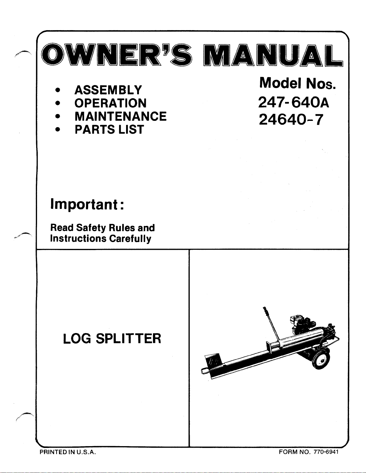
3. Place flat washers (A) on axle, then wheels and
secure with collars and set screws (B). See figures
1 and 2.
4. The engagement handle is partly assembled, pivot
handle upward into positionand secure with shoulder
bolt (C). See figure 3.
ENGAGEMENT HANDLE
SHOULDER BOLT (C)
SHOULDER BOLT
tEADY IN
FIGURE 3
5. Tighten both shoulder bolts securely.
OPERATION
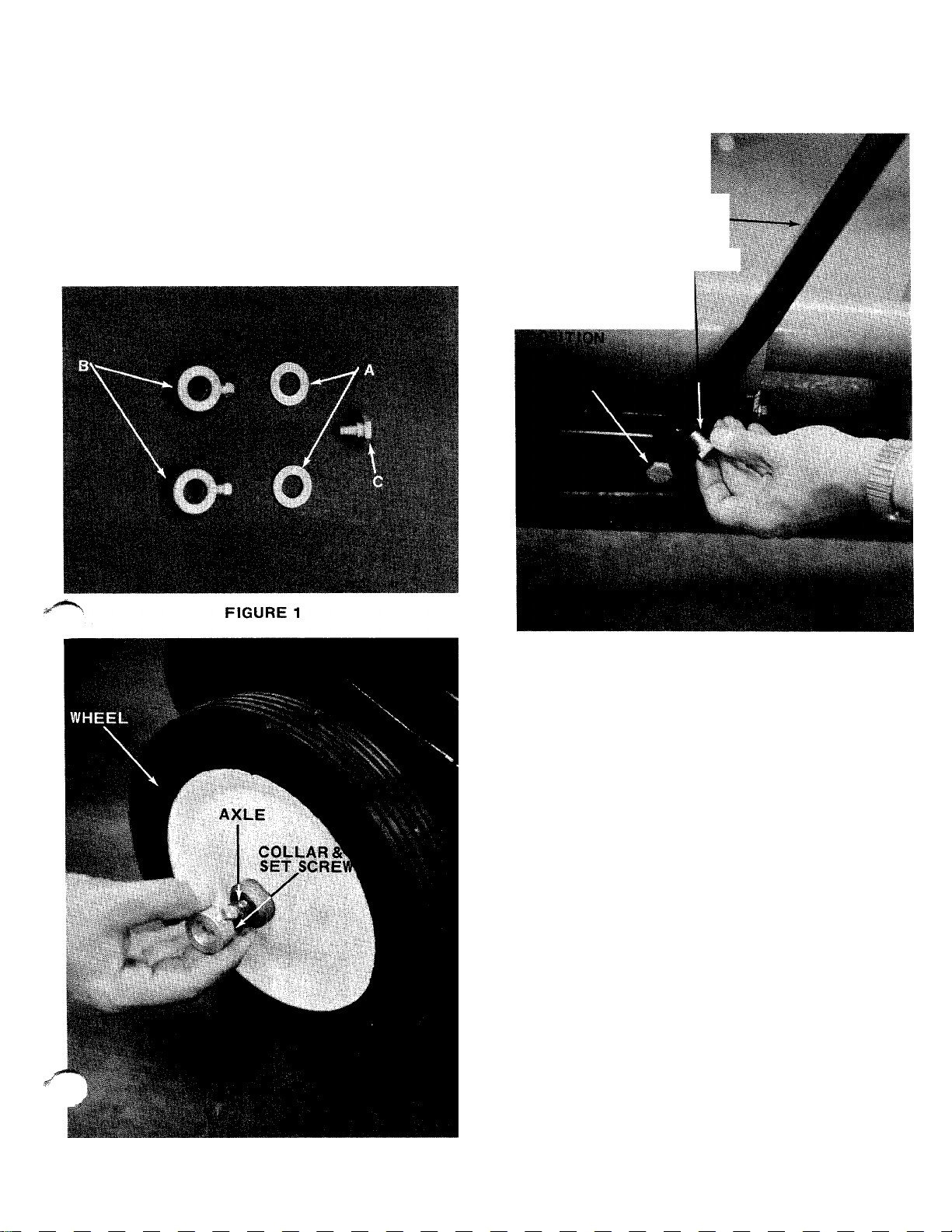
1. Service engine with gas and oil. See engine manual
packed with log splitter for complete instructions
for the care and maintenance of engine. READ
DIRECTIONS CAREFULLY.
CAUTION
A
You must not operate log splitter
without proper amount of oil in reser
voir tank.
FIGURE 2
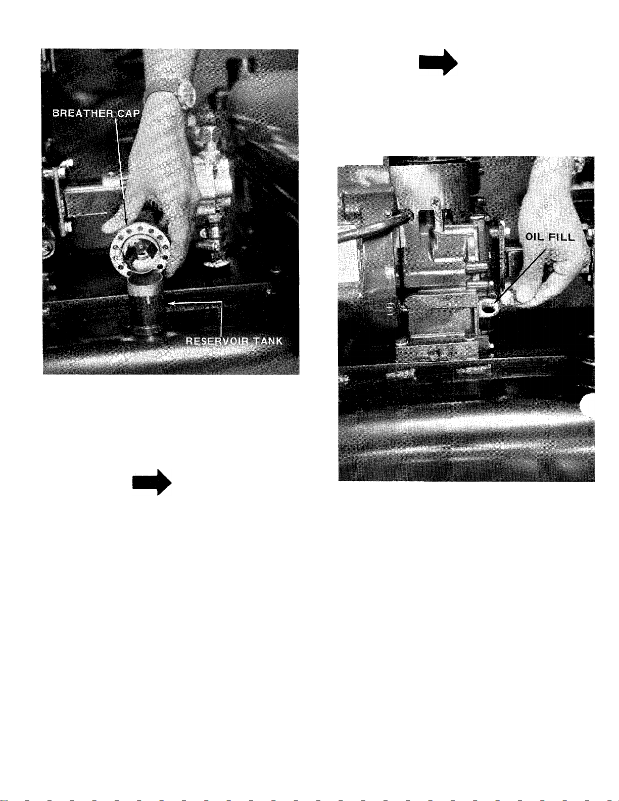
2. Remove the breather cap from reservoir tank.
See figure 4.
Page 4
NOTE
Carburetors are preset at the factory.
DO NOT attempt to make adjustments
at this time. See carburetor instructions
outlined under CARBURETOR AD
JUSTMENT.
FIGURE 4
3. The hydraulic system takes 4-1/2 gallons of
low 30 HD only detergent oil. Fill the reservoir
tank to the bottom of the fill tube.
NOTE
You can not get all the oil in the
system until after the engine is run.
Replace the breather cap.
BEFORE STARTING
During initial break-in period, oil level should be
watched closely. See ENGINE MAINTENANCE.
Use MS classification oil. Do not use oils marked
only MM or ML or unmarked.
Above 32° use SAE 30; below 32° use SAE 10W.
These recommendations must be followed for best
performance and long life.
Change oil first two (2) hours of operation and
check oil level every five (5) operating hours or
each time equipment is used.
Change oil every twenty-five (25) operating hours
or sooner if equipment is operated in extremely
dusty of dirty conditions. 4
FIGURE 5
TO START ENGINE
1. Place control lever (on engine) in run position.
See figure 6.
2. Move choke lever to CHOKE position. See
figure 7.
3. Rewind starter-use quick full arm stroke. Keep
firm grip on handle and return rope slowly.
TO STOP ENGINE
1. Move control levertoSTOP position. See figure 6.
2. Remove high tension wire from spark plug to
prevent accidental starting by children while
equipment is unattended.
Page 5

FIGURE 6
USING YOUR LOG SPLITTER
Your log splitter is designed for safe, efficient,
operation. CARE, OF COURSE, MUST BE EXER
CISED THAT HANDS ARE KEPT AWAY FROM ALL
MOVING PARTS.
A. Set throttle at maximum speed.
B. Engagement handle has three positions: Forward-
moves ram towards wedge. Neutral - ram stops
in place. Reverse - ram returns. See figure 8.
FIGURE 7
NOTE
After engine has been serviced,
finish filling oil reservoir. Start
engine and operate engagement handle
so the ram makes two complete strokes.
CAUTION
A
This is to purge the hydraulic system
of air.Continued operation will cause
permanent damage to pump and cyl
inder. Stop engine and finish filling
reservoir tank. It will take about 3
quarts of oil. See figure 4.
FIGURE 8
C. Maximum length that can be split is 23”
D. Place log on beam and hold in place with right
hand. See figure 9.
FIGURE 9
Page 6

E. Slowly move engagement handle forward until
ram rests against log. Release engagement
handle (Neutral).
F. Remove your hand from the log and step behind
the ram. See figure 10.
FIGURE 12
MAINTENANCE
FIGURE 10
G. Move engagement handle forward until log is
split.
NOTE
If you attempt to run the ram beyond
its normal stroke it will automatically
return the engagement handle to neutral.
H. Move the engagement handle to the rear to return
ram.
DANGER ^
Never attempt to cut a log in half
with the log splitter. See figure 11.
Never stand next to the ram when
operating. See figure 12. Always
stand behind the ram.
^^1^ ^ WARNING I
If ram takes longer than 30 seconds
to complete full forward cycle, check
strainer tube assembly.
A
Always stop engine and disconnect
spark plug wire before doing any
maintenance.
RAM OPERATION
If the ram does not move smoothly, run the ram its
full stroke several times to clear out air in the
system. If this does not correct the problem see
strainer tube assembly paragraph. (Page 7).
RETURN COLLAR
Adjust the return collar so it is 2 inches from the
front edge of the wedge.. See figure 13.
CAUTION
FIGURE 11 FIGURE 13
Page 7

HOSE CLAMPS
Check the hose clamps on the bottom of the pump
for proper tightness before each use. See figure 14.
lose clamps on the return hose should be checked
once a season. See figure 15.
BREATHER CAP
Clean breather cap when dirty. See figure 4.
A. Wash breather in detergent and water.
B. Air dry.
C. Lubricate with one tablespoon of 10W 30 oil.
STRAINER TUBE ASSEMBLY
If the ram does not move back and forth smoothly
the strainer tube assembly may be clogged.
To clean follow these steps.
A. Remove your engine bolts and lockwashers.
See figure 16.
HOSE
CLAMP
OIL RESERVOIR
FIGURE 14
FIGURE 15
FIGURE 16
B. Loosen hose clamps (either one) on the bottom
of the pump.
C. Lift engine and pump assembly and rotate to
one side. See figure 16.
D. With a wrench, remove strainer tube assembly.
See figure 17.
It is important to keep the oil clean in the reservoir
tank. Replace with 4-1/2 gallons of 10W 30 HD only
detergent oil if contaminated (e.g. water in tank).
FIGURE 17
Page 8

E. Clean and reassemble using a hydraulic sealant
on the threads.
ENGINE MAINTENANCE
To obtain long life and trouble-free service from
your engine, certain normal maintenance must be
performed as outlined below:
1. Change oil in crankcase after first two (2) hours
of operation. Then, follow instructions outlined
on page 4.
3. Cleaning engine-This is an aircooled engine
which operates most efficiently when the cooling
fins are clean.
Clean cylinder fins and underside of tank or housing_
thoroughly of all accumulated grass and debris
4. Air Cleaner. (See figure 19).
a.
Paper Type Element. Remove every 10 hours or
oftener if under dusty conditions. Tap to remove
loose dirt and/or blow from inside out with low
pressure air. Replace if torn or perforated or
when plugged to maintain proper carburetor setting
(50 hours). DO NOT WASH IN ANY LIQUID AND
DO NOT OIL.
Paper Element
FIGURE 18
A
Disconnect high tension wire at spark
plug to prevent accidental starting
of engine. Unscrew oil drain plug
located on side at bottom of engine
See figure 18.
Always tip engine towards oil drain
hole. Be sure oil drains completely.
Replace oil drain plug and refill with oil as directed
on page 4 or engine nameplate.
2. Check oil every five (5) operating hours or each
time equipment is used.
CAUTION
NOTE
Element
'Attaching Screw
FIGURE 19
CARBURETOR ADJUSTMENTS (See figure 20)
Do not make unnecessary adjustment. Factory settings
are correct for most application. If adjustments are
needed, proceed as follows:
1. Close power adjusting needle (figure 20) by
turning to right (clockwise). Close finger tight
only. Forcing will cause damage.
2. Open one turn (counterclockwise).
3. Close idle adjusting needle (figure 20) by turning
to right (clockwise). Close finger tight only.
Forcing will cause damage.
4. Open one and one-half (1 1/2) turns (counter
clockwise).
5. Start engine. Follow starting instructions page 4—
6. With throttle open (carburetor control at RUN
FAST position) adjust power adjusting needle
one-eighth (1/8) turn at a time forward or back
ward until engine runs smoothly. If engine tends
to stall under load enrich mixture slightly (counter
clockwise).
Page 9

Hold throttle lever closed or move carburetor
control to IDLE or SLOW position and adjust
idle adjusting needle until engine runs smoothly
proceeding in step six (6) above.
Allow several seconds between each adjust
ment when performing either step six (6) or
seven (7) to allow engine to react to new setting.
STORAGE
INSTRUCTIONS
In event engine is to be stored for any length of
time (30 days or more), prepare as foliows;
1. Drain gasoline by tipping or by syphon hose,
then run engine until remainder is used and tank
and carburetor are empty.
CAUTION
A
Drain into container outdoors away
from fire or flame.
Drain carburetor by running engine until it stops.
2.
Inside protection of engine for storage is per
3.
formed by removing spark plug and pouring one
ounce of SAE 30 oil through spark plug hole
into cylinder. Crank engine, without starting,
several times to spread oil over cylinder walls.
4. Never store outside without a waterproof cover.
FIGURE 20
Page 10

047-640^
24640'^
10
Page 11

LIST FOR LOG SPLITTER MODELS 247-640A and 24640-7
..ef.
No.
Part
No.
710-0331 HexScr. 3/8-24x2.25” Lg.* 25
1
13275
2
3 727-0203
4 737-0155
5
717-0364
6
736-0119
Color
Code
Description
New
Part
Cam Piate
High Pressure Hose Ass'y.
11.0” Lg.
Reducing Bushing N
Valve N
L.-Wash. 3/8” Scr.*
N
N
7 712-0241 Hex Nut 3/8-24 Thd.* 32
8
08118
9
737-0153
10 737-0154
732-0342
11
12
732-0341
13304
13
14
721-0159
15 13302
13314
7
726-0173
749-0251
18
19 13310
736-0119
20
Grip
Return Elbow N
Cylinder nipple .75”x4.5” Lg . N
Spring Clip N
Cylinder Return Spring
Cylinder Ass’y.
‘‘0”-Ring
Push Cylinder Ass’y.
Spring Hook Ass’y. N
Hose Clamp
Engagement Handle
Cylinder Holding Plate
L-Wash. 5/16” Scr.*
N
N
N
N
N
N
N
21 710-0528 Hex Scr. 5/16-18x1.25” Lg.
22
23
24
13305
13312
710-0494
”I”-Beam Ass’y. Comp.
Return Collar Ass’y.
Sq.Hd.SetScr.5/16-18x .38”
_________________________________________________________________________
N
N
Lg.
LL_
Ref.
No.
Part
No.
Color
Code
Description
13291 Engagement Lever Ass’y.
26 738-0258 Shoulder Scr. 3/8-16 Thd.
27
13280
Strainer Tube Ass’y.
28 727-0204 Return Hose
29
711-0169
30 734-0584
31 736-0237
13276
751-0224
33
34
727-0205
35
737-0151
717-0363
36
Coilar
Wheel Ass’y. Comp.
FI.-Wash. .656 I.D.x I.OOTh
Tank Ass’y. Complete
Breather Cap
Inlet Hose
Inlet Nipple
Pump - Complete(bJ£R.ST£i^)
37 737-0152 High Pressure Elbow
38
710-0376
39 712-0267
13295 Coupl ing Support Brkt. Ass’y
40
41
714-0114
42
710-0237
43 710-0528
44
717-0374 Flexible Coupling Comp.
45
46 714-0507
47 736-0142
48 711-0660
HexScr.5/16-18x 1.00” Lg
HexNut5/16-18 Thd.*
Sq. Key 1/4”x2.00” Lg.*
HexScr. 5/16-24X .62” Lg.*
Hex Scr. 5/16-18x1.25”Lg.
Engine
Cotter Pin 3/32” Dia.X .75”
Fl.-Wash. .28I.D.x.50”O.C
Clevis Pin
New
Part
N
N
N
d.
N
N
N
N
N
N
*
^ N
*
N
Lg.*
).
N
‘For faster service obtain standard nuts, bolts and washers locally. If these Items cannot be obtained locally, order by part
number and size as shown on parts list.
The engine is not under warranty by the log splitter manufacturer. If repairs or service is needed
on the engine, please contact your neorest authorized engine service outlet. Check the "Yellow
Pages” of your telephone book under "Engines — Gasoline.”
Find It Fast
InThs
Yellow Pages
11
Page 12

PARTS INFORMATION
POWER EQUIPMENT PARTS AND SERVICE
Parts and service for all MTD manufactured power
equipment are available through the authorized service
firms listed below. All orders should specify the model
number of your unit, ports numbers, description of parts
and the quantity of each part required.
ALABAMA BIRMINGHAM
Auto E lactric & Carburetor Co.. .2625 4th Ave. S.. 35233
ARKANSAS NORTH LITTLE ROCK
Sutton's Lawn Mower Shop .Rt. 4, Box 368
Mity Mite Motors, Inc;
CALIFORNIA SAN BERNARDINO
Lawn Mower Supply Co
J.W. Jewett Co
Luttig & Severson .................. 2030 28th St............... 95818
COLORADO DENVER
South Denver Lown Equip
CONNECTICUT SUFFIELD
The Jones & Ramsey Co
FLORIDA JACKSONVILLE
Rodeo Distributors
Moz-AII of Florida, Inc............ 365 Greco Ave
GEORGIA EAST POINT
East Point Cycle & Key
ILLINOIS LYONS
Keen Edge Co
INDIANA ELKHART
Ports & Soles Inc..................... 2101 Industrial Pkwy. ..46514
IOWA DUBUQUE
Power Lawn & Garden Equip. .2551 J.F. Kennedy —52001
KANSAS WICHITA
Hixon, Inc
LOUISIANA NEW ORLEANS
Suhren Engine Co.................... 8330 Eorhort Blvd
MARYLAND TAKOMA PARK
Center Supply Co
MASSACHUSETTS SPRINGFIELD
Morton B. Collins Co............... 300 Birnie Ave............01107
MICHIGAN MOUNT CLEMENS
Power Equipment Dist
Lorenz Service Co
MINNESOTA MINNETONKA
Hance Distributing Inc
MISSISSIPPI BILOXI
Biloxi Soles & Service, Inc. ....506 Caillovot St
MISSOURI KANSAS CITY
Automotive Equip. Service ..3117 Holmes St
Henzler, Inc
NEW YORK CARTHAGE
Gamble Dist., Inc...................... West End Ave
Kimber's, Inc
...................................
FORT SMITH
............
.........
SAN FRANCISCO
.........................
SACRAMENTO
....
.......
.................
CORAL GABLES
.......
..........................
.................
...........
LANSING
...................
............
ST. LOUIS
...............................
SYRACUSE
.............................
2515 Towson Ave
25608 E. Baseline .... 92410
981 Folsom St
527 West Evans
850 Thompsonvi He Rd. 06078
2403 Morket St
2834 Church St
8615 Ogden Ave
3030 Mascot
6867 NewHompshireAve. 20012
36463 South Uratiot... 48043
2500 S. Pennsylvonio .. 48900
11212 Woyzato Blvd. ..55343
2015 Lemoy Ferry Rd. 63125
115 N. Geddes St
..........
....
............
........
........
...........
.........
........
............
.......
..........
...........
.....
72117
72901
94107
80223
32206
33146
30344
60534
67204
....
70118
39533
64109
13619
13204
BRIGGS & STRATTON, TECUMSEH AND PEERLESS
PARTS AND SERVICE
Briggs & Stratton, Tecumseh and Peerless parts ;
service should be handled by your nearest authoriz
engine service firm. Check the yellow pages of your
telephone directory under the listing Engines ______________
Gasoline, Briggs & Stratton or Tecumseh Lauson
NORTH CAROLINA GREENSBORO
Dixie Sales Company
Smith Hardware Co
OHIO WADSWORTH
National Central ........................687 Seville Rd
Bleckrie, Inc
Stebe's Mid-State Mower Supply Box 366
Sunshine Wholesola Tire Outlet Route 224
McClure Lawn 8i Garden Supply...1 11 ^ Lexington Ave. , 44903
OKLAHOMA MUSKOGEE
Victory Motors, Inc...................605 S. Cherokee
Ado Auto Supply
OREGON PORTLAND
Kenton Supply Co
PENNSYLVANIA LANCASTER
Roub Supply Co
Bluomont Co
TENNESSEE KNOXVILLE
Master Repair Service
Memphis Cycle & Supply Co. 421 Monroe Ave
American Solos & Service, Inc. . 1922 Lynnbrook .381 lo
TEXAS DALLAS
Morr Brothers, Inc. ................ 423 E. Jefferson
Bullard Supply Co
Cotto 8. Putty, (nc
Woodson Solos Corp.............. 1702 N. Sylvanio
UTAH SALT LAKE CITY
A-1 Engine & Mower Co......... 437 E. 9th St..............84111
VERMONT BURLINGTON
Vermont Appliance Co
VIRGINIA RICHMOND
RBI Corp..................................... 963 Myers St
WASHINGTON SEATTLE
Bailey's Rebuild, Inc
WEST VIRGINIA CHARLESTON
Young's, Inc
WISCONSIN APPLETON
Automotive Supply Co............123 S. Linwood Ave. ..54911
..............................
............................
...............................
.............
GOLDSBORO
...................
CLEVELAND
CARROLL
WILLARD
MANSFIELD
ADA
.....................
.....................
......................
PITTSBURGH
..........
MEMPHIS
HOUSTON
..................
SAN ANTONIO
...................
FORT WORTH
...........
..............
327 Battleground Ave.. 27402
515 N. George St
7900 Lorain Ave
301 E. 12th St
8216 N. Denver Ave. . 97217
James & Mulberry Sts...17604
11 125 Frankstown Rd.. 15235
2423 Broodwoy, N.E...379’"“
2409 Commerce St
P.O. Box 2408
44 Lakeside Avo
1325 E. Madison St. ...98102
233 Virginia St., E. ...25301
__________
.......
.........
.......
................
.............
....
...........
.......
.....
...
..........
....
..........
............
27530
44281
44102
43112
44890
74401
74820
38 i
75203
77003
78206
76111
05401
23260
WARRANTY PARTS AND SERVICE POLICY
The purpose of worronty is to protect the customer from defects in workmonship ond materials, defects which ore NOT detected
at the time of moriufocture. It does not provide for the unlimited ond unrestricted replocement of parts. Use and mointonance ore
the responsibility of the customer. The manufacturer cannot assume responsibility for conditions over which it has no control.
Simply put, if it's the manufacturer's foult, it's the manufacturer's responsibility; if it's the customer's fault, it’s the customer’s
responsibility.
CLAIMS AGAINST THE MANUFACTURER S
WARRANTY INCLUDES
Replacement of Missing Ports on new equipment. 1. Model Number of unit involved.
Replacement of Defective Ports within the worronty period. 2. Dote unit was purchased or first pot into service,
nair of Defects within the warranty period. 3- Dote of failure.
PRODUCTS INC
5389 WEST 130th STREET • P. 0. BOX 2741 CLEVELAND OHIO 44111
Ait claims MUST be substantiated with the following
information:
4. Nature of failure.
 Loading...