

Page 1
OUTDOOR POWER EQUIPMENT
for all seasons
.75
3-1/2 H.P.
LOG SPUTTER
Important:
Read Safety Rules and Instructions Carefully
PRINTED IN U.S.A.
Model Numbers
245-638-000
24638S
Thank you for purchasing
an American-built product.
FORM NO. 770-3995
Page 2

INDEX
Safe Operation Practices............................................ 3
Assembly Instructions................................................. 5
Operation
Maintenance . . .
...................................................................
...
..................................................... 9
Instructions given with this symbol are for personal
A
safety. Be si re to follow them.
LIMITED WARRANTY
♦
♦
♦
♦
♦
♦
For one year from the date of orig
repair or replace, at its option, free (
part or parts found to be defective i
the movement of any power equipm
chaser. Transportation charges for j
ty must be paid by the purchaser un
This warranty will not apply to any part which has become inoperative due to misuse, ex
cessive use, accident, neglect, improper maintenance, alterations, or unless the unit has
been operated and maintained in ac cordance with the instructions furnished. This warran
ty does not apply tothe engine, mol or, battery, battery chargeror component parts thereof.
Please refer to the applicable man jfacturer’s warranty on these items.
inal retail purchase, MTD PRODUCTS INC will either
>f charge, F.O.B. factory or authorized service firm, any
T material or workmanship. Transportation charges for
ent unit or attachment are the responsibility of the puriny parts submitted for replacement under this warranless such return is requested by MTD PRODUCTS INC.
7
Off-Season Storage
Trouble Shooting Chart
Illustrated Parts
Repair Parts Lists.....................................13, 14
........................................
..................................
........................................
12, 14
10
11
♦
♦
♦
♦
♦
♦
♦
I
♦
♦
♦
♦
I
This unit is equipped with an internal conbustion engine and should not be used on or near any unim
proved forest-covered, brush-covered or gniss-covered land unless the engine's exhaust system is equipped
with a spark arrester meeting applicable lo ;al or state laws (if any). If a spark arrester is used, it should be
maintained in effective working order by ths operator.
This warranty will not apply where the unit has been used commercially.
Warranty service is available throu(|h your local authorized service dealer or distributor. If
you do not know the dealer or distri jutor in your area, please write tothe Customer Service
Department of MTD.
The return of a complete unit will r ot be accepted by the factory unless prior written per
mission has been extended by MTD.
This warranty gives you specific l< gal rights. You may also have other rights which vary
from state to state.
Ai
WARNING (
♦
♦
♦
♦
♦
♦
In the State of California the above is rec uired by law (Section 4442 of the California Public Resources
Code). Other states may have similar laws. Federal laws apply on federal lands. A spark arrester muffler is
available at your nearest engine authorized service center.
Page 3
IMPORTANT
A
It is suggested that this manual be read in its entirety before attempting to assemble or operate. Keep this manual
-*cka safe place for future reference and for ordering replacement parts.
.is unit is shipped WITHOUT GASOLINE or 01L. After assembly, see separate engine manual for proper fuel and
engine oil recommendations.
Your log splitter is a precision piece of power equipment, not a plaything. Therefore exercise extreme caution at
all times.
SAFE OPERATION PRACTICES FOR LOG SPLITTERS
TRAINING
1. Know the controls and how to stop quicklyREADTHIS OWNER'S MANUAL.
2. Do not allow children to operate. Do not allow
adults to operate it without proper instruction.
Only persons well acquainted with these rules of
safe operation should be allowed to use your log
splitter.
3. No one should operate this unit while intoxicated
or while taking medication that impairs the senses
or reactions.
4. Never use your splitter for any other purpose
than splitting wood. It is designed for this use
only and any other use may cause an injury.
5. Only the operator is to be near your log splitter
during use. Keep all others, including pets, a
minimum of 20 feet away from your work zone.
Flying wood can be hazardous.
6. Don't step over your splitter when engine is
running. You may trip or accidentally activate
ram if you step over, if you need to get to the
other side, walk around.
PREPARATION
1.
Do not wear loose fitting clothing that could get
caught on the moving parts.
Do not operate equipment when barefoot or
2.
wearing open sandals. Always wear safety shoes or
heavy boots. A dropped log can seriously injure
your foot.
Check the fuel before starting the engine. Do not
3.
fill the gasoline tank indoors, when the engine is
running, or while the engine is still hot. Wipe off
any spilled gasoline before starting the engine.
Use only in daylight or in good artificial light.
4.
Never operate your splitter on slippery, wet,
5.
muddy, or icy surfaces. Safe footing is essential in
preventing accidents. Never operate your splitter
while attached to a towing vehicle.
Always wear safety glasses or goggles while oper
ating your log splitter. A piece of splitting log
could fly off and hit your eyes.
Both ends of each log must be cut square. This
7.
will prevent the log from flying out of the splitter
while under pressure.
OPERATION
1. Do not change the engine governor settings or
overspeed the engine. Excessive engine speeds are
dangerous.
2. Never place hands or feet between log and split
ting wedge or between log and ram during forward
or reverse stroke. To do so may result in crushed
or amputated fingers or toes, or worse, you may
lose an arm or foot.
3. If the equipment should start to vibrate abnor
mally, stop the engine and check immediately for
the cause. Vibration is generally a warning of
trouble.
4. When cleaning, repairing or inspecting, make
certain all moving parts have stopped. Disconnect
the spark plug wire, and keep the wire away from
the plug to prevent accidental starting.
5. Handle gasoline with care. It is highly flammable.
A. Use approved gasoline container.
B. Never remove cap or add gasoline to a running
or hot engine or fill fuel tank indoors; Wipe
up spilled gasoline.
C. Don't run engine in an enclosed area. Ex
haust gases contain carbon monoxide. This
odorless gas can be deadly when inhaled.
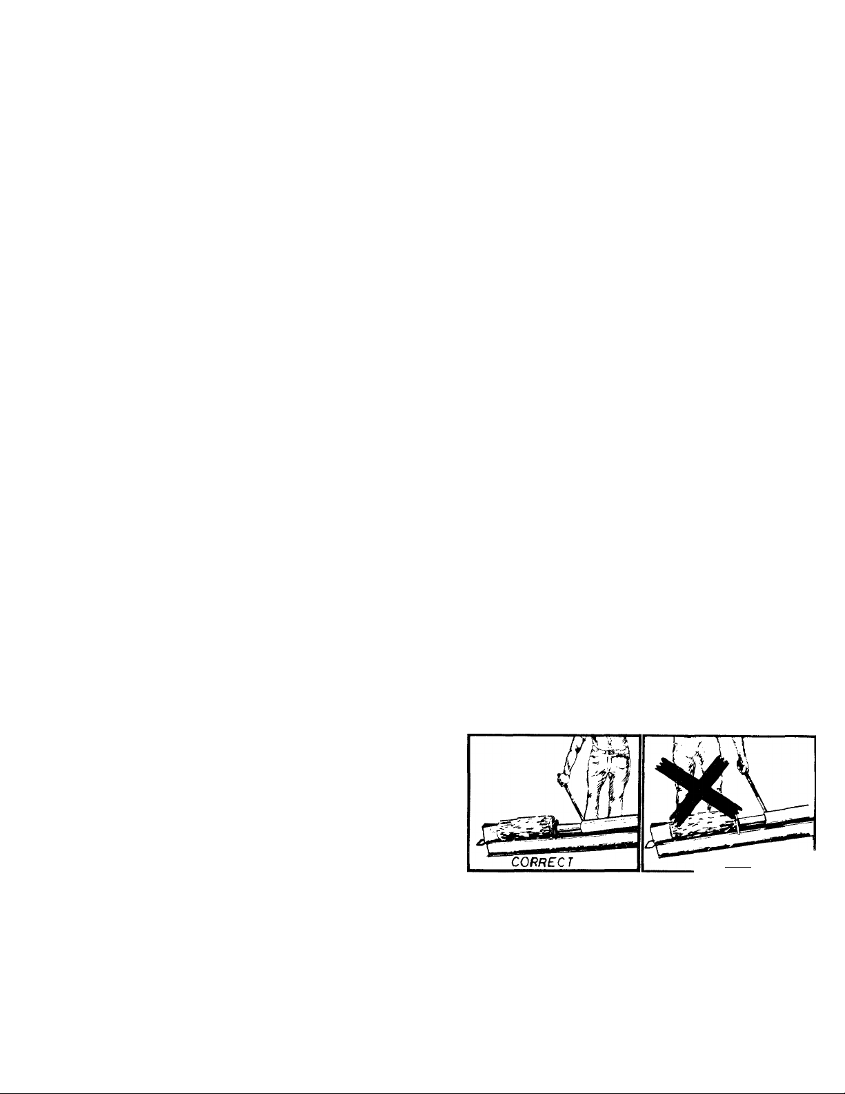
6. Stand behind the ram when operating. See draw
ings.
NEVEPf
7. Be careful not to touch the muffler after the
engine has been running. It is HOT.
8. Never try to split two logs on top of each other.
One may fly out and injure you.
9. When loading the log splitter, place your hands on
the sides of the log, not at the ends.
10. For logs that are not cut square, the longest
portion of the log should be rotated down and
the most square end placed against the ram.
Page 4

11. Never attempt to split wood across the. g ain.
Some types of wood may burst or fly out of
your splitter and result in injury to you ar a
bystander.
12. Never leave your log splitter unattended with the
engine running. Shut off the engine if you are
leaving your splitter, even for a short periof of
of time. Someone could accidentally activât« the
ram and be injured.
13. Only use your hand to operate the ram or control
lever. Never use your foot or a rope or any ether
extension device. This could result in your inabil
ity to stop your splitter quickly enough and
cause an injury.
14. Only operate your splitter on the level ground and
not on the side of a hill. It could tip, or ro ling
logs or poor footing could cause an accident.
This also prevents the spillage of gas from the
tank.
MAINTENANCE and STORAGE
1. Don't operate your splitter in poor mechenical
condition or when in need of repair.
2. Keep all nuts, bolts, screws, hose clampi and
hydraulic fittings tight to be sure equipment is
in safe working condition.
3. Replace all damaged or worn parts such a; hy
draulic hoses and fittings immediately with man
ufacturer approved replacement parts.
4.
Never store the equipment with gasoline in the
tank inside of a building where fumes may reach
an open flame or spark. Allow the engine to cool
before storing in any enclosure.
To reduce fire hazard keep engine free of gras
5.
leaves, wood chips, excessive grease and oil.
The hydraulic system of your log splitter re
quires the careful inspection along with the
mechanical parts. Be sure to replace frayed,
kinked, cracked or otherwise damaged hydraulic
components.
Fluid escaping from a very small hole can almost
7.
be invisible. Do not check for leaks with your
hand. Escaping fluid under pressure can have
sufficient force to penetrate skin, causing serious
personal injury. Leaks can be located by passing
a piece of cardboard or wood over the suspected
leak and look for discoloration.
Should it become necessary to loosen or remove
any hydraulic fitting or line, be sure to relieve
all pressure by shutting off the engine and moving
the control handle back and forth several times.
Don't remove the cap from the hydraulic tank or
9.
reservoir while your log splitter is running. Hot
oil under pressure could cause injury.
10. Never store outside without a waterproof cover.
Rain will cause rust on the inside of the cylinder
CAUTION
THIS UNIT SHOULD NOT BE TOWED ON ANY
STREET, HIGFWAY OR PUBLIC ROAD. ANY
LICENSING NEEDED TO COMPLY WITH THE
EXISTING FEE ERAL, LOCAL OR STATE VEH
ICLE REQUIREMENTS IS THE SOLE RESPONSI
BILITY OF THE PURCHASER.
Page 5
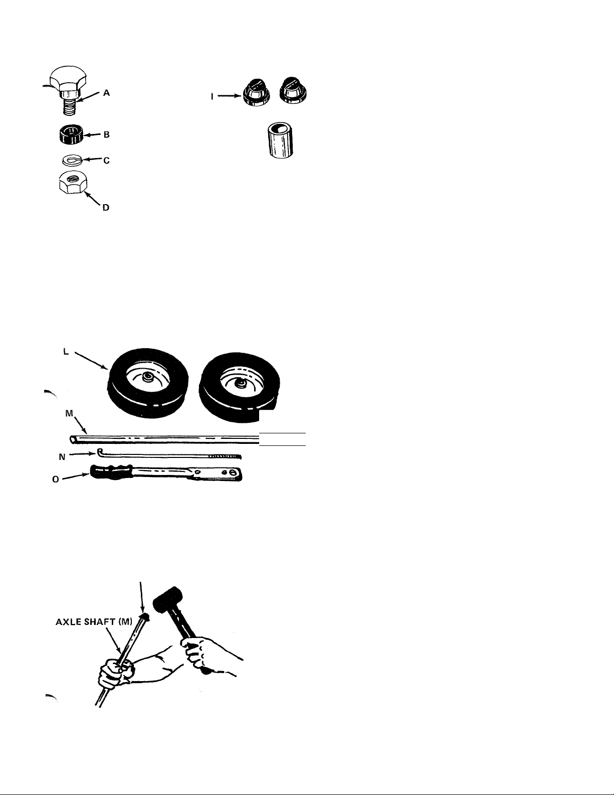
FIGURE 1
G-
H-
ASSEMBLY INSTRUCTIONS
TOOLS REQUIRED
(1) Raw Hide or Plastic Hammer
(1) 3/4" Wrench or Adjustable Wrench
(1) Pair of Pliers
OTHER MATERIALS NEEDED
One gallon of regular grade gasoline (for engine)
1-1/2 pints of SAE 30 or 10W30 oil (for engine).
Approximately 2 gallons of Dexron TL automatic
transmission fluid (may be obtained at any local
service station or auto parts store).
Funnel
CONTENTS OF HARDWARE PACK (See figure 1):
A
B
C
D
E
f
G (2)
H
1
J
Shoulder Bolt
(1)
Rubber Washer
(1)
Lock Washer
(1)
Hex Nut
(1)
Ferrule
(1)
Hairpin Cotter
(1)
Flat Washers
Cotter Pin
(1)
Axle Push Caps
(2)
Spacer
(1)
figure 2
AXLE PUSH CAP (I)
FIGURES
------
LOOSE PARTS IN CARTON (See figure 2):
L (2) Wheels
M
s
N
0
1. Remove log splitter and loose parts from carton.
2. Using a raw hide or plastic hammer, tap one axle
3. Slide one wheel onto the axle shaft.
4. Slide the axle through the frame from the right
Axle Shaft
(1)
Engagement Rod
(1)
Engagement Handle
(1)
Make certain all parts and literature have been
removed from the carton before the carton is
discarded.
push cap (I) on one end of axle shaft (M). See
figure 3.
hand side of the splitter (as viewed from standing
behind it).
Page 6

LEFT HAND SIDE
OF SPLITTER
FIGURE4
Slide spacer (J) onto axle shaft on the left hand
side of the splitter. Spacer should be on the engine
side of the splitter. See figure 4. Place the other
wheel on the axle.
FIGURE 5
6. Secure wheel to axle with push cap (I). See figure-
5.
PUSH CAP (I)
7. Hook the bent end of the engagement rod (N)
into the lever on top of the pump. See figure 6.
Next, place one flat washer (G) over the rod.
Insert the cotter pin (H) into the hole in the rod
and secure by bending the ends of the cotter pin
in opposite directions.
FIGURE 6
Page 7

9. Place the flattened end of the engagement handle
(0) down through the slotted bracket beside the
beam. Place shoulder bolt (A) through the bottom
hole in engagement handle. Place rubber washer
(B) on shoulder bolt. Secure to bracket with lock
washer (C) and hex nut (D). See figure 7.
LEVER ON
PUMP
FIGURES
ENGAGEMENT
HANDLE
NOTCH
OPERATION
BEFORE STARTING
1. Fill reservoir tank on log splitter with approxmately 2 gallons of Dexron II automatic trans
mission fluid as follows. Check oil level before
each use.
A. Block up front of log splitter so the beam is
level.
B. Remove the oil check plug from the back of
the log splitter. See figure 9. If oil starts to
come out of the hole, oil level is correct. If it
does not, remove the cap from the breather
tube and add oil until oil starts out of the
check hole.
C. Replace oil check plug. Replace cap on the
breather tube. Remove block from under
front of beam.
10. Place the engagement handle in the notch in the
slotted bracket (Reverse position). See figures 8
and 11. Thread the ferrule (E) onto the end of
engagement rod.
11. Push the lever on top of the pump as far toward
the rear of the unit as it will go as shown in figure
8. Hold it in this position and adjust the ferrule on
the engagement rod so the ferrule lines up with the
hole in the engagement handle.
12. Secure the ferrule to engagement handle with
flat washer (G) and hairpin cotter (F).
FUNNEL
FIGURES
Page 8

NOTE
DO NOT operate log splitter without
proper amount of oil in reservoir tank
(beam).
2. Fill sump with oil as instructed in the sepa'ate
engine manual packed with your unit.
3. Fill fuel tank, using clean, fresh, regular grade
automotive gasoline. Fill tank completely.
NOTE
Refer to engine manual packed with
log splitter for complete instructions
for the care and maintenance of en
gine. READ DIRECTIONS CARE
FULLY.
TO START ENGINE
1. Place throttle control lever (on engine) in CHC KE
position, towards the front of splitter. See fi jure
10.
NOTE
USING YOUR LOG SPLITTER
Your log splitter is designed for safe, efficient
operation. BE CAREFUL TO KEEP HANDS AND
FEET AWAY FROM MOVING PARTS.
Engagement handle has three positions: (See figure 11,
Forward - ram moves toward wedge.
Neutral - ram stops in place.
Reverse - ram returns.
ENGAGEMENT HANDLE
IN NEUTRAL POSITION.
ENGAGEMENT HANDLE
HELD IN FORWARD
POSITION.
A warm engine may not require
choking. Simply place lever in RUN
position.
2. Grasp starter handle, place one foot on wheel and
pull starter handle with a quick, full arm stroke.
Return rope slowly to the engine.
3. After engine starts, move throttle control lover
to RUN position.
TO STOP ENGINE
1. Move throttle control lever to STOP posit on.
2. Disconnect spafk plug wire from spark plu<i to
prevent accidental starting while equipment is
unattended.
ENGAGEMENT HANDLE
LOCKED IN REVERSE
POSITION.
FIGURE 11
Maximum length that can be split is 20".
TO OPERATE LOG SPLITTER:
1. Set throttle at maximum speed.
2. Place log on beam and hold in place with right
hand.
3. Slowly move engagement handle forward until
ram rests against log. Release engagement handle
(Neutral).
4. Remove your hand from the log and step behind
the ram.
5. Move engagement handle forward until log is split.
6. Move the engagement handle to the rear to return
ram.
The ram should take approximately 22 seconds to
make a complete cycle. This speed may vary de
pending on throttle setting and temperature of oil.
NOTE
If you lock the engagement handle in
the reverse slot, the ram will return
until it hits the engagement bracket,
which will throw the engagement
handle into neutral automatically.
Page 9

A
I WARNING J
Never attempt to cut a log in half with
the log splitter.
Never stand next to the ram when
operating. Always stand behind the
ram.
MAINTENANCE
Ac WARNING \
Always stop engine and disconnect
spark plug wire before performing any
maintenance or adjustments.
ENGINE OIL
Change oil first two (2) hours of operation. Check
oil level every five (5) operating hours or each time
equipment is used.
Change oil every twenty-five (25) operating hours or
sooner if equipment is operated in extremely dusty
or dirty conditions.
Refer to engine manual for quantity and type of oil.
LOG SPLITTER RESERVOIR OIL
Check oil
">efer to
ction.
Change the oil in the reservoir every 100 hours of
operation. Remove the six hex bolts, lock washers
and hex nuts which hold the end plate to the beam.
Remove the plate and drain the oil. Be prepared to
catch oil in a suitable container.
in log splitter reservoir before every use.
"Before Starting" under OPERATION
When the oil is drained from the reservoir, clean the
strainer tube assembly as follows.
1. Remove the hose clamp at the inlet hose (bottom
hose). See figure 12.
2.
Pull the inlet hose off the fitting at the beam.
Using an adjustable wrench, remove the fitting
from the beam.
Reach inside the end of the beam and pull out the
strainer tube assembly.
4.
Clean the strainer tube assembly and reassemble in
reverse order.
Reassemble the end plate. Refill oil reservoir with
approximately 2 gallons of Dexron II automatic
transmission fluid as instructed in "Before Starting"
under OPERATION section.
HOSE CLAMPS
Check the hose clamps on the bottom of the pump
for proper tightness before each use.
Hose clamps on the return hose should be checked
once a season.
CARBURETOR ADJUSTMENTS
A
If any adjustments are made to the
engine while the engine is running
(e.g. carburetor), keep clear of all
moving parts. Be careful of heated
surfaces and muffler.
Refer to engine manual packed with your unit for
carburetor adjustment information.
BELT ADJUSTMENT
{ WARNING {
Drain the oil and flush the reservoir
tank assembly and hoses each time
repair work is performed on the tank,
hydraulic pump or valve. Contaminants
in the oil will damage the hydraulic
components.
END
PLATE
-X BOLTS
LOCK WASHERS
HEX NUTS
FIGURE 12
NOTE
1. Disconnect the spark plug wire from the spark
plug and ground against the engine block.
2. Drain the gasoline from the fuel tank or place a
piece of plastic under the cap to prevent leakage.
3. Tip the splitter on one side.
4. Remove four self-tapping screws from the bottom
belt cover and frame. Refer to figure 13.
5. Loosen the three engine mounting bolts using a
1/2" wrench. Refer to figure 15.
6. Slide the engine outward to tighten the belt until
there is approximately 1/2" deflection. Tighten
engine mounting bolts securely.
BELT REPLACEMENT
1. Disconnect the spark plug wire from the spark
plug and ground against the engine block.
2. Drain the gasoline from the fuel tank or place a
piece of plastic under the cap to prevent leakage.
3. Tip the splitter on one side.
4. Remove four self-tapping screws from the bottom
belt cover and frame. See figure 13.
Page 10

FIGURE 13
FIGURE 15
5. Using a 9/16" wrench, remove the engine pu ley
by removing the hex bolt and lock washer. See
figure 14. Slip the pulley and belt off.
NOTE
Be careful not to lose the square key
on the crankshaft.
HEX BOLT
7. install the new belt and replace the engine pulley.
8. Slide the engine outward to tighten the new belt
until there is approximately 1/2" deflection.
Tighten engine mounting bolts securely.
OFF-SEASON STORAGE
In event engine is to be stored for any length of time
(30 days or more), prepare as follows:
1. Drain gasoline by tipping or by siphon hose, then
run engine until remainder is used and tank and
carburetor are empty.
CAUTION
A.
Drain gasoline into container outdoors,
away from fire or flame.
2. Drain carburetor by running engine until it stops
from lack of fuel.
3. Protect the inside of engine for storage by
removing spark plug and pouring one ounce of
SAE 30 oil through spark plug hole into cylinder.
Crank engine, without starting, several times to
spread oil over cylinder walls.
4. Never store outside without a waterproof cover.
FIGURE 14
6. Loosen the three engine mounting bolts us ng a
1/2" wrench. See figure 15.
NOTE
When storing any type of power equip
ment in an unventilated or metal
storage shed, care should be taken to
rustproof the equipment. Using a light
oil or silicone, coat the equipment,
especially the beam and all moving
parts.
10
Page 11

TROUBLE SHOOTING CHART
SYMPTOM
^ Engine fails to start
2. Hard starting or loss of
power
3. Engine overheats A. Carburetor not adjusted
4. Will not split logs
POSSIBLE CAUSE (S)
A. Check fuel tank for gas.
B. Spark plug lead wire
disconnected.
C. Faulty spark plug.
A. Spark plug wire loose.
B. Dirty air cleaner.
properly.
B. Air flow restricted.
C. Engine oil level low.
A. Reservoir oil level low.
B. Belt is slipping.
C. Pump setting incorrect.
SOLUTION
A. Fill tank if empty.
B. Connect lead wire.
C. Spark should jump gap between
control electrode and side electrode.
If spark does not jump, replace the
spark plug.
A. Connect and tighten spark plug wire.
B. Clean air cleaner as described in
engine manual.
A. Adjust carburetor. See engine manual.
B. Remove blower housing and clean as
described in the engine manual.
C. Fill crankcase with the proper oil.
A. Check and fill oil reservoir tank as
instructed in Operation Section.
B. Tighten belt or replace if worn. See
maintenance section.
C. Adjust pump setting to 3,000 p.s.i.*
5. Leaking cylinder A. Broken seals.
B. Scored cylinder.
fE: For repairs beyond minor adjustments, please contact your local service dealer.
'Should be performed by an authorized service dealer only.
A. Replace seals.*
B. Replace cylinder.*
11
Page 12

Model 638
IF YOU WRITE TO US ABOUT THIS AftllClE
OR IF YOU ORDER REPLACEMENT PARTS AL
WAYS MENTION THIS MODEL & SERIAL NO
MODEL
12
NOTE
This instruction manual covers various models
and all specifications shown do not necessari
ly apply to your model. Specifications subject
to change without notice or obligation.
NOTE: The engine is not under warranty by
the log splitter manufacturer... If repairs or
service is needed on the engine, please
contact your nearest author
ized engine service outlet.
Check the “Yellow Pages” of
your telephone book under
“Engines—Gasoline.”
Find If Fast
In The
Yellow Pages
Page 13

Model 638
PARTS LIST FOR MODEL 638 LOG SPLITTER
PART
i>lO.
1
IMO.
717-0816
2 720-0157 Grip 47
3
737-0196
4 719-0270 Pusher Plate
5 738-0601
6 749-0663 Engagement Handle
7 711-0628
8
712-0267 Hex Nut 5/16-18 Thd.* 54
9 736-0119
10 781-0021
11
12
13
781-0069 Oil Tank Ass'y. Comp N
781-0038 Wedge Ass'y. N 56 726-0132
710-0298 Hex Bolt 5/8-18 X 3.50" 57
COLOR
CODE
NEW
REF.
DESCRIPTION
2-1/2" Cylinder Ass'y. Comp
PARI
N 46
NO.
PART
NO.
741-0116
726-0214
90° Elbow Adapter
N
48
49
N
781-0071 Frame - Motor
714-0133
Shoulder Bolt 5/8" Dia.
X .660" Lg. 1/2-13 Thd. N 51 712-0267
52 736-0119
N
Adjustment Ferrule 53 727-0302 High Pressure Hose
737-0183 Adapter - or Boss to MJIC
L.-Wash. 5/16" I.D.*
Strainer Tube Ass'y- N 55 737-0182
737-0184 Adapter 1/2" Tube 9/16-18
Lg. (Grade 5)
14 736-0158 L.-Wash. 5/8" I.D. 58
15 712-0337
Hex Nut 5/8-18 Thd.*
59
N
717-0803
714-0507
16 712-0798 Hex Nut 3/8-16 Thd.*
17 736-0169 L.-Wash. 3/8" I.D.* 60 736-0264
18
19
735-0144
738-0143 Shoulder Bolt .498 x .340 61
20 781-0024
21 738-0140 Shoulder Bolt .437" Dia. 63
Lq2
732-0352 Extension Spring .50" O.D. 12 "0"-Ring
Rubber Wash.
727-0301
Engagement Brkt. 62
727-0300 Suction Hose .75" I.D.
726-0146 Hose Clamp 1/4" I.D.
X .180" Lg. 64 737-0191
X 4.25" Lg. 65 712-0267
29 Engine - B & S 66 736-0119
30
31
734-0736
Wheel Ass'y. Comp. 10.0"
X 2.75
750-0118 Sleeve .632" I.D. x .875"
67
736-0275 Fl.-Wash. .343" I.D. x .687"
N
68
710-0442 Hex Bolt 5/16-18 X 1.50"
O.D. X .90" Lg.
32 710-0599 Hex Wash. Hd. Self Tap.
Scr. 1/4-20 X .50" Lg. 70
33 756-0425
1/2" V-Pulley 7/8" I.D. x
7/8" I.D. X 3-1/4" O.D.
34 754-0278
"V"-Belt(4D 1/2" Vx 73 712-0203 Hex Nut 3/4" Thd.*
30" Lg.
35 781-0008
36
37
736-0119
710-0152 Hex Bolt 3/8-24 X 1.0" Lg.*
38 756-0426
Belt Cover
L.-Wash. 5/16" I.D.* 76 745-0174
1/2 (4L) "V"-Pulley 5/8" MJ-1/4-18 NP N
I.D. X 3-1/2" O.D.
69 710-0604
721-0205 Gasket N
71
72
781-0023 End Plate N ■
721-0203 Gasket N
74 736-0364
75
77
781-0036 Filler Tube Ass'y. N
737-0197 45° Male Adapter 7/16-20
78 721-0204
39 710-0938 Set Scr. 1/4-28 X .25" Lg.
40 736-0105
41
710-0649
Bell.-Wash..40" I.D. x .88"
O.D.
Hex Wash. Hd. TT-Tap Scr.
79 710-0920
80
712-0338 Hex Nut 11/16-12Thd.
81 710-0117
3/8-16 X .87" Lg.
42 712-0123
43 710-0376
44
736-0119 L.-Wash. 5/16" I.D."
747-0458 Axle Shaft 5/8" Dia. x 25.5" Lg.
45
Hex Nut 5/16-24 Thd.*
Hex Bolt 5/16-18 X 1.00" Lg.*
82
83
747-0493
736-0264
84 714-0104
_________________________1___
COLOR
CODE
DESCRIPTION
Flange Brg. w/Flats .631" l.[
Push Cap 5/8" Dia. Rod
Sq. Key 3/16" x3/16" x
1.50" Lg.*
Hex Nut 5/16-18 Thd.*
L.-Wash. 5/16" I.D.*
9/16-18 to 7/16-20
Adapter 3/4" Tubing to 3/4
-16 M-Boss
Hose Clamp 5/8" I.D.
or M-Boss
Valve Ass'y.
Cotter Pin 3/32" Dia. x .75"
Lg.*
Fl.-Wash. 344" I.D. x .62"
O.D. X .063
Return Hose .50" I.D.
Adapter 1.0" Tube 1-1/16-
Hex Nut 5/16-18 Thd.*
L.-Wash. 5/16" I.D.*
O.D. X .062
Lg.*
Hex Hd. Tap Scr. 5/16"
L.-Wash. 3/4." I.D.*
Oil Fill Cap
"0"-Ring .92" I.D. x 1.16"
O.D. X .116 Dia. N
Hex Bolt 3/4" X 4.0" Lg.
Hex Bolt 5/16-24 X 1.00" Lg.
(Grade 5)
Engagement Rod 16.75" Lg.
Fl.-Wash. .344" I.D. x .62"
O.D. X .063
Hair Pin Cotter 5/16" Dia.
NEW
PART
).
N
N
N
N
N
N
N
jr faster service obtain standard nuts, bolts and washers locallv- If these items cannot be obtained locally, order by part
number and size as shown on parts list.
13
Page 14

Model 638
1&2
2-1/2" DIA. CYLINDER
PARTS LIST FOR MODEL 638
REF.
NO.
PART NO. DESCRIPTION
1 717-0816
2 753-0392 2- /2" Cyi. Kit "0"-Ring Set N
C\ linder Ass'y- Comp.
NEW
PART
N
14
Page 15

Page 16

MTD PRODUCTS INC ..........................................................
P.O. BOX 3690D • CLEVELAND OHIO 44136
YSRO-MSN COMPANY
 Loading...