

Page 1
OLIVER’S
MANUAL
3 1/2 H.P.
LOG SPUTTERS
.75
Model Numbers
242-635A
24635A
Important:
Read Safety Rules and
Instructions Carefully
Thank you for purchasing an
American built product.
PRINTED IN U.S.A.
_____________________________________
FORM NO. 770-1814
Page 2

INDEX
Safe Operation Practices ..............................................3
Assembly Instructions ...................................................4
Operation
Adjustments
......................................................................
.....
............................................................
r
LIMITED WARRANTY
♦
♦
♦
♦
♦
♦
♦
♦
For one year from the date of original retail purchase, MTD PRODUCTS INC will either
repairer replace, at its option, free of charge, F.O.B. factory or authorized service firm, any
part or parts found to be defective in material or workmanship. Transportation charges for
the movement of any power equipment unit or attachment are the responsibility of the pur
chaser. Transportation charges for any parts submitted for replacement under this warran
ty must be paid by the purchaser Unless such return is requested by MTD PRODUCTS INC.
This warranty will not apply to any part which has becomejnoperative due to misuse, ex
cessive use, accident, neglect, improper maintenance, alterations, or unless the unit has
been operated and maintained in accordance with the instructions furnished. This warran
ty does not apply to the engine, motor, battery, battery chargeror component parts thereof.
Please refer to the applicable manufacturer’s warranty on these items.
Maintenance ..................................................................5
Off-Season Storage
4
5
Illustrated Parts
Repair Parts List
.............................
....................................................
.................................................
..........................
8
10, 12
11, 13
♦
♦
♦
♦
♦
♦
This warranty will not apply where the unit has been used commercially.
Warranty service is available through your local authorized service dealer or distributor. If
you do not know the dealer or distributor in your area, please write to the Customer Service
Department of MTD.
The return of a complete unit will not be accepted by the factory unless prior written per
mission has been extended by MTD.
This warranty gives you specific legal rights. You may also have other rights which vary
from state to state.
V
WARNING
TO PURCHASERS
OF INTERNAL COMBUSTION ENGINE EQUIPPED
MACHINERY OR DEVICES IN THE STATE OF CALIFORNIA
The equipment which you have just purchased does not have a spark arrester. If this equipment is used on
any forest covered land, brush covered land, or grass covered unimproved land in the State of California,
before using on such land, the California law requires that a spark arrester be provided. In addition, spark
arrester is required by law to be in effective working order. The spark arrester must be attached to the
exhaust system and comply with Section 4442 of the California Public Resources Code.
Page 3

IMPORTANT
It is suggested that this manual be read in its entirety before attempting to assemble or operate. Keep this
manual in a safe place for future reference and for ordering replacement parts.
This unit is shipped WITHOUT GASOLINE or OIL. After assembly, see operating section of this manual
for proper fuel-and engine oil recommendations.
Your log splitter is a precision piece of power equipment, not a plaything. Therefore exercise extreme caution
at all times.
SAFE OPERATION PRACTICES FOR LOG SPLITTERS
4.
TRAINING
1. Know the controls and how to stop quicklyREAD THE OWNER'S MANUAL
2. Do not allow children to operate. Do not allow
adults to operate it without proper instruction.
Only persons well acquainted with these rules of
safe operation should be allowed to use your log
splitter.
When cleaning, repairing or inspecting, make
certain all moving parts have stopped. Disconnect
the spark plug wire, and keep the wire away from
the plug to prevent accidental starting.
5.
Handle gasoline with care. It is highly flammable.
A. Use approved gasoline container.
B. Never remove cap or add gasoline to a running
or hot engine or fill fuel tank indoors. Wipe
up spilled gasoline.
C. Open doors if engine is run in garage-
exhaust fumes are dangerous. Do not run
engine indoors.
.^REPARATION
Do not wear loose fitting clothing that could get
1.
caught on the moving parts.
Do not operate equipment when barefoot or wear
2.
ing open Sandies. Always wear substantial foot
wear.
Check the fuel before starting the engine. Do not
3.
fill the gasoline tank indoors, when the engine is
running, or while the engine is still hot. Wipe off
any spilled gasoline before starting the engine.
Use only in daylight or in good artificial light.
4.
Never operate the equipment in the rain. Always
5.
be sure of your footing.
OPERATION
1. Do not change the engine governor settings or
overspeed the engine. Excessive engine speeds are
dangerous.
Do not put hands or feet near rotating or moving
parts.
3. If the equipment should start to vibrate abnor
mally, stop the engine and check immediately for
the cause. Vibration is generally a warning of
trouble.
6.
Always stand beside the controls when operating
the log splitter.
7.
Be careful not to touch the muffler after the
engine has been running. It is HOT.
MAINTENANCE and STORAGE
1. Keep all nuts, bolts and screws tight to be sure
equipment is in safe working condition.
2. Never store the equipment with gasoline in the
tank inside of a building where fumes may reach
an open flame of spark. Allow the engine to cool
before storing in any enclosure.
3. To reduce fire hazard keep engine free of grass,
leaves, wood chips, excessive grease and oil.
4. Do not change the engine governor settings or
overspeed the engine. Excessive engine speeds
are dangerous.
5. Never store outside without a waterproof cover.
Rain will cause rust on the unit.
Page 4
ASSEMBLY
USING YOUR LOG SPLITTER
NOTE
This unit shipped WITHOUT GASSOLI NE or OIL. After assembly, see
separate engine manual for proper fuel
and engine oil recommendations.
1. Remove the log splitter, loose parts, and literature
from the carton. Make certain all parts and
literature have been removed before the carton is
discarded.
2. Thread the engagement handle into the engage
ment handle bracket as shown in figure 1.
t\GACf N'lF NT HANDLE
NOTE
Reference to right or left hand side of
the unit is determined when standing
behind the unit, at the engine.
Your log splitter is designed for safe, efficient
operation. CARE, OF COURSE, MUST BE EXER
CISED THAT HANDS ARE KEPT AWAY FROM
MOVING PARTS.
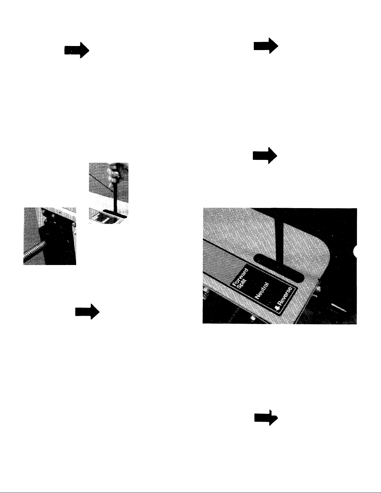
Engagement handle has three positions: (See figure 2)
Forward—Wedge moves toward engine.
Neutral—Wedge stops in place.
Reverse—Wedge returns.
NOTE
When the engagerrtent handle is
released, it will automatically return
to "NEUTRAL" position.
I
FIGURE 1
OPERATION
NOTE
Refer to engine manual packed with
log splitter for complete instructions
for the care and maintenance of
engine. READ DIRECTIONS CARE
FULLY.
Fill sump with oil as instructed in the separate
1.
engine manual.
Fill fuel tank, using clean, fresh, regular grade
2.
automotive gasoline. Fill tank completely.
Before operating log splitter for the first time,
lubricate the two large screws on the wedge and
screw assembly with engine oil. Screws must be
oiled at least every two operating hours or more
often if necessary.
Start engine as instructed in the separate engine
manual.
To stop engine, move throttle control lever to
5.
STOP position. Disconnect and ground the spark
plug wire to prevent accidental starting while
equipment is unattended.
FIGURE 2
Maximum length that can be split is 24".
1. Set throttle at maximum speed.
2. Place log on frame assembly.
3. Stand beside the engagement handle on the left
side of the unit.
4. Move engagement handle forward until log is split,
then release handle.
NOTE
After the log is split, do not keep the
engagement handle in the forward
position or the wedge assembly will be
jammed.
5. Move the engagement handle to the reverse
position to return ram.
Page 5
NOTE
If the wedge assembly becomes
jammed, turn the jack shaft spindle
assembly counterclockwise until the
wedge can be returned. See figure 3.
A large adjustable wrench is required.
JACK SHAFT SPINDLE
ASSEMBLY
FIGURE 4
MAINTENANCE
\ WARNING \
FIGURE 3
WARNING
Never attempt to cut a log in half
against the grain (cross ways). Never
stand next to the log when operating
the splitter.
ADJUSTMENTS
CARBURETOR ADJUSTMENTS
t warning!
If any adjustments are made to the
engine while the engine is running
(e.g. carburetor), disengage all clutches.
Keep clear of all moving parts. Be
careful of heated suVfaces and muffler.
Refer to engine manual packed with your unit for
carburetor adjustment information.
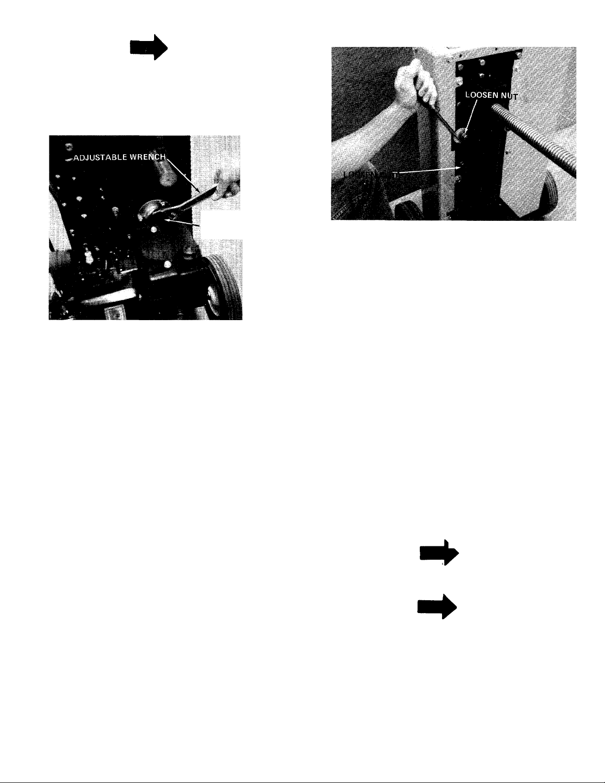
CHAIN ADJUSTMENT
The chain must be adjusted after the first hour of
/•^“^ial operation and every ten hours thereafter.
adjust the chain, loosen the two nuts shown in
figure 4. Place a screwdriver on the chain adjuster as
shown in figure 4. Pivot the chain adjuster by pulling
downward on the screwdriver to take the slack out of
the chain. Tighten the two nuts.
®
Always stop engine and disconnect
spark plug wire before performing any
maintenance or adjustments.
ENGINE OIL
Change oil first two (2) hours of operation and check
oil level every five (5) operating hours or each time
equipment is used.
Change oil every twenty-five (25) operating hours or
sooner if equipment is operated in extremely dusty or
dirty conditions.
Refer to engine manual for quantity and type of oil.
WEDGE AND SCREW ASSEMBLY
Lubricate the two screws on the wedge and screw
assembly with engine oil every two operating hours or
more often if necessary.
BELT REPLACEMENT
NOTE
If belt replacement is required, it is
advisable to replace both belts at the
same time,
NOTE
Reference to right or left hand side of
the unit is determined when standing
behind the unit, at the engine.
It is suggested that all instructions be read through
before beginning belt replacement.
1. Disconnect and ground the spark plug wire against
the engine block.
2. Using a 1/2" wrench, remove the top cover by
removing the five self tapping screws which secure
it to the side covers.
Page 6

.1 I'l •' ‘ .* ’•’ ■' ■,■'■ ■'
FIGURE 5
3. Block the frame of the unit on the left hand side.
Remove the left wheel by removing the cotter pin
and flat washer. Slide wheel off. See figure 6.
5. Remove the 5-1/2" bolt and spacer, located on the
left hand side of unit, which act as a belt keeper.
Two 9/16" wrenches are required. See. figure 8.
FIGURE 8
COTTER PIN
FIGURE 6
4. Using a 1/2" wrench, remove the right and left
hand side covers. See figure 7.
LEFTSIDE COVER^
^-------\—
6. Remove the two idler pulleys as shown in figure
9. Two 9/16" wrenches are required.
FIGURE 9
RIGHT SIDECOVER
FIGURE 7
,V- -
7. Hold the engagement lever in the forward positio.
(spark plug wire must be disconnected). Pull the
recoil starter rope to rotate the chain until the
master link can be located. Remove the master
link and chain. See figure 10.
Page 7

MASTER LINK
FIGURE 10
8. Remove the two belt keepers on the right hand
side of frame using two 7/16" wrenches. See
figure 11.
10. Block up the front of the frame as shown in figure
13. Remove the three bottom bolts, lock washers
and nuts. See figure 13.
FIGURE 13
FIGURE 11
9. Remove the top three bolts, lock washers and nuts
as shown in figure 12. Two 9/16" wrenches are
required.
THREE TOP BOL
11. Lift up on the rear frame so it will clear the
large sprocket. Pull back to separate front and
rear frames. See figure 14.
REAR FRAME
LARGE
SPROCKET
FRONT FRAME
FIGURE 14
FIGURE 12
12. Slip belts between jack shaft bearing and front
frame. See figure 15.
Page 8

UUihiiiiMmtíM
FIGURE 15
13. Reassemble with new belts, following instructions
in reverse order.
NOTE
When reassembling the frame halves, be
certain that the jackshaft bearing is
properly seated into the hole in the
front frame. Secure frame halves with
one top and bottom bolt, finger tight
only. Check position of bearing. Then
reassemble rest of bolts, tightening
securely.
‘NOTE
Belts and chain must be reassembled as
shown in illustration on page 10. If
assembled incorrectly, log splitter will
operate in reverse.
OFF-SEASON STORAGE
In event engine is to be stored for any length of time
(30 days or more), prepare as follows:
1. Drain gasoline by tipping or by siphon hose, then
run engine until remainder is used and tank and
carburetor are empty.
CAUTION
A
Drain into container outdoors away
from fire or flame.
Drain carburetor by running engine until it stops
from lack of fuel.
3.
Protect the inside of engine for storage by
removing spark plug and pouring one ounce of
SAE 30 oil through spark plug hole into cylinder.
Crank engine, without starting, several times to
spread oil over cylinder walls.
4.
Never store outside without a waterproof cover.
Page 9

Notes
Page 10

Model 635
IF YOU WRITE TO US ABOUT THIS ARTICLE
OR IF YOU ORDER REPLACEMENT PARTS AL
WAYS MENTION THIS MODEL & SERIAL NO
MODEL
10
Page 11

Model 635
PARTS LIST FOR MODEL 635 LOG SPLITTER
Ref.
•No.
1
2
PART
No.
____
710-0649
__
COLOR
CODE
DESCRIPTION
Engine
Hex. Wash. SF Tapp Scr. 36
3/8" X 7/8" Lg.
710-0693 Hex Bolt 3/8-16 X 4.5" Lg.
3
4
750-0537
Spacer 3/8 I.D. x 5/8 O.D. x 38
X 2-5/8 Lg.
5 14822
Spring Retainer Bracket
6 712-0798 Hex Nut 3/8-16 Thd.*
736-0169
7
732-0121
8
9 738-0147
747-0389 Engagement Handle
10
11 14823
12 14809
714-0105
13
14
756-0381
714-0104 Internal Cotter Pin 1/8" Dia. 48
15
738-0322 ShId. Bolt
16
14716 Engagement Handle Brkt.
17
L-Wash. 3/8 I.D.^
Spring
Shid. Bolt
Lever Return Bracket
Motor Mounting Plate Ass'ySq. Key 3/16 x 1.0 Lg.
Step Pulley
Ass'y-
710-0830
18
736-0169
19
756-0225
712-0798
756-0225
710-0344 Hex Bolt 3/8-16 X 1.5" Lg.* 55
23
714-0474
24
Hex Bolt 3/8-24 x 3.0 Lg.* 51
L-Wash. 3/8 I.D.*
Idler Pulley 2-3/4
Hex Nut 3/8-16 Thd.*
Idler Pulley 2-3/4
Cotter Pin 1/8" Dia. x 3/4"
Lg-*
25 14811
712-0798
26
736-0169
27
756-0382
28
738-0525
29
714-0139
30
713-0298
31
710-0600
32
Engagement Bracket Ass'y.
Hex Nut 3/8-16 Thd.*
L-Wash. 3/8" I.D.*
Engine Pulley
Jack Shaft Spindle
Sq. Key 3/16 x 2.0 Lg.*
Sprocket 12T #20 Chain
Hex. Wash. TT Tapp Scr.
3/8 X 1/2" Lg.
33 14721
34 710-0118
Belt Cover R.H.
Hex Bolt 5/16-18 X.75" Lg.
NEW
PARI
Ref.
PART
No.
35 08253
741-0919
No.
COLOR
CODE
DESCRIPTION
Small Bearing Housing
Ball Bearing .787 I.D. x
1.85 O.D.
738-0147 Shid. Bolt
37
750-0531 Spacer .38 I.D. x 62 O.D.
4.5 Lg.
N
39 736-0119
L-Wash. 5/16 I.D.*
40 736-0133 FI.-Wash. 3/8 I.D. x 1.25
O.D. x.10 Thd.
41 712-0798
42 711-0735
Hex Nut 3/8-16 Thd.*
Stud 1/4" X 2-7/8" Lg.
N 44 712-0267 Hex Nut 5/16-18 Thd.*
N
712-0287 Hex Nut 1/4-20 Thd.*
45
N 46 719-0258 Flywheel
47 750-0528 Spacer 3/8 I.D. x .50 O.D.
N
710-0649
X 18
Hex Wash. SF Tapp Scr.
3/8 X 7/8
N
749-0493
49
712-0267 Hex Nut 5/16-18 Thd.*
50
Engine Brace
736-0119 L-Wash. 5/16 I.D.*
52 736-0329
L-Wash. 1/4" I.D.*
53 710-0428 Hex Bolt 1/4-24X 1-1/4"
Lg.*
54
710-0237 Hex Bolt 5/16-24 X 5/8" Lg.
736-0119 L-Wash. 5/16 I.D.* 1
56 712-0375 Hex Cent. L.-Nut 3/8-16 Thd.
712-0267 Hex Nut 5/16-18 Thd.*
57
N
58 14700
59
710-0237 Hex Bolt 5/16-24 X 5/8"
Motor Mount Cup N
Lg.*
N
60
61
734-0736
736-0116
Wheel Ass'y. 10.0 x 2.75
Fl.-Wash. 5/8 I.D. x 93 O.D.
X .06
N
62
63
64 736-0119
N
65
66 736-0119
67
714-0115
720-0143 Control Grip
712-0267
712-0318
Cotter Pin 1/8" X 1.0" Lg.*
L-Wash. 5/16 I.D.*
Hex Nut 5/16-18 Thd.*
L-Wash. 5/16 I.D.*
Hex Jam Nut 5/8-18 Thd.
NEW
PART
N
N
N
N
*
*For faster service obtain standard nuts and bolts locally. If
these items cannot be obtained locally, order by part
number and size as shown on parts list.
11
Page 12

Model 635
/ /
12
Page 13

Model 635
PARTS LIST FOR MODEL 635 LOG SPLITTER
NEW
PART
No.
No.
754-0244 V-Belt 1/2x40" Lg.
1
COLOR
CODE
DESCRIPTION
Ref.
PART
No.
20 710-0649
(Reverse)
2 754-0235
V-Belt 1/2x35 Lg.
21
(Forward)
3 14719
4
14720
14722
5
711-0628
6
747-0388 Lever Rod
7
710-0118 Hex Bolt 5/16-18 X. 75" Lg.* 25 736-0169
8
9 14714
10
14707
736-0119 L-Wash. 5/16" I.D.*
11
End Cover
L.H. Belt Cover
Comp. Wedge & Screw Ass'yAdjustment Ferrule 24 736-0133 Fl.-Wash. 3/8 I.D. x 1.25
Sprocket Hub Ass'y-
Frame Weldment Ass'y.
N
22
N 3/8 X 1/2" Lg.
N
23 14715
N
N
26
N
27
28
12 712-0267 Hex Nut 5/16-18 Thd.*
13 710-0831 Hex Bolt 3/8-16x5.5" Lg.*
14 712-0798
736-0105
15
16
736-0258
17 06605
736-0105
18
Hex Nut 3/8-16 Thd.* 30
Bell Wash. 3/8" I.D.
FI. Wash. 3/8 I.D. x 1.0 O.D.
X 13 32
Chain Adjuster
Bell Wash. 3/8" I.D.
19 712-0798 Hex Nut 3/8-16 Thd.*
N
29 14709 Idler Bracket Ass'y. N
31 710-0412 Hex Bolt 1/4-24x3/4" Lg.
33 710-0650 Hex Wash. SF Tapp Scr.
34
PART
No.
COLOR
CODE
DESCRIPTION
Hex Wash. SF Tapp Scr.
3/8 X 7/8" Lg.
713-0302
131 Link Chain #.420
713-0154 Master Link #.420
710-0773 Hex Wash. TT Tapp Scr.
10 Tooth Sprocket Ass'y. N
O.D. X 10 Thd.
L-Wash. 3/8" I.D.*
710-0152 Hex Bolt 3/8-24 X 1.0" Lg.*
710-0344
Hex Bolt 3/8-16 X 1.5" Lg.*
741-0133 Ball Bearing .50 I.D. x 1.38
O.D. X .437
736-0463
Fl.-Wash. 1/4 I.D. x 5/8
O.D. X .06
741-0355
Ball Bearing N
5/16x7/8
710-0600
Hex Wash. SF Tapp Scr.
5/16 X-1/2
NEW
PART
N
13
Page 14

MTD PRODUCTS INC
P.O.BOX 36900 • CLEVELAND, OHIO 44136
.....................................................
YaRD-МЭН COMPANY
 Loading...