

Page 1

OWNER’S GUIDE
OUTDOOR POWER EQUIPMENT
for all seasons
Spring
3 H.P.
EDGER
1.00
Important:
Read Safety Rules and Instructions Carefully
Model Numbers
246-604-000
24604C
Thank you for purchasing
an Annerican-built product.
PRINTED IN U.S.A.
FORM NO. 770-5201A
Page 2

INDEX
Safe Operation Practices
Assembly Instructions
Controls .......................................................................... 7
Operation ........................................................................ 8
Lubrication
......................................................................
................................................
.....................................................
Ins
for
▲
the
3
4
9
ructions given with this symbol are
personal safety. Be sure to follow
m.
Maintenance
Off-Season Storage
Trouble Shooting Chart...................................................11
Illustrated Parts
Replacement Parts List...................................................13
.................................................................
........................................................
...............................................................
12
lU
t. .WARNING {
This unit is equipped with an internal comb ustion engine and should not be used on or near any unim
proved forest-covered, brush-covered or grass-covered land unless the engine's exhaust system is equipped
with a spark arrester meeting applicable local or state laws (if any). If a spark arrester is used, it should be
maintained in effective working order by the operator.
In the State of California the above is required by law (Section 4442 of the California Public Resources
Code). Other states may have similar laws. Federal laws apply on federal lands. A spark arrester muffler is
available at your nearest engine authorized service center.
Page 3

WARNING
A
To reduce the potential for any injury, comply with the following safety instructions. Failure to comply with the instructions may result in personal injury.
t
SAFE OPERATION PRACTICES FOR EDGERS
TRAINING
1. Read this owner's manual carefully in its en
tirety before attempting to assemble or operate
this machine. Be completely familiar with the
controls and the proper use of this machine be
fore operating it. Keep this manual in a safe place
for future and regular reference and for ordering
replacement parts.
2. Your edger is a precision piece of power equip
ment, not a plaything. Therefore, exercise extreme
caution at all times.
3. Never allow children to operate a power edger.
Only persons well acquainted with these rules of
safe operation should be allowed to use your
edger.
4. Keep the area of operation clear of all persons,
particularly small children and pets. Stop engine
when they are in the vicinity of your edger. Al
though the area of operation should be complete
ly cleared of foreign objects, an object may have
been overlooked and could be accidently thrown
by the edger in any direction and cause serious
personal injury to the operator or any others
allowed in the area.
5. No one should operate this unit while intoxicated
or while taking medication that impairs the senses
or reactions.
PREPARATION
1. Thoroughly inspect the area where the equip
ment is to be used. Remove all stones, sticks,
wire, bones and other foreign objects which
could be picked up and thrown by the edger in
any direction and cause serious personal injury to
the operator or any others allowed in the area.
2. Do not operate equipment when barefoot or wear
ing open sandals. Always wear substantial foot
wear.
3. Checkthefuel before starting the engine. Gasoline
is an extremely flammable fuel. Do not fill the
gasoline tank indoors, while the engine is running,
or while the engine is still hot. Wipe off any
spilled gasoline before starting the engine as it
may cause a fire or explosion.
4. Disengage the blade clutch on units so equipped
before starting the engine.
5. Never attempt to make a wheel adjustment while
the engine is running.
6. Never operate the equipment in wet grass. Always
be sure of your footing. A slip and fall can cause
serious personal injury. Keep a firm hold on the
handle and walk, never run.
OPERATION
1. Never operate this edger unless wearing safety
glasses or some other suitable eye protection at
all times the engine is running.
2. Do not change the engine governor settings or
overspeed the engine.
3. Do not put hands or feet near or under rotating
parts. Keep clear of the discharge opening at all
times as the rotating blade can cause injury.
4. Stop the blade when crossing gravel drives, walks
or roads.
5. After striking a foreign object, stop the engine,
remove the wire from the spark plug, and thor
oughly inspect the edger for any damage. Repair
the damage before restarting and operating the
edger.
6. If the equipment should start to vibrate abnor
mally, stop the engine and check immediately
for the cause. Vibration is generally a warning
of trouble.
7. Stop the engine whenever you leave the equip
ment, before cleaning the guard assembly, and
when making any repairs or inspections.
8. Before cleaning, repairing or inspecting, make
certain the blade and all moving parts have stop
ped. Disconnect the spark plug wire, and keep
the wire away from the spark plug to prevent
accidental starting.
9. Do not run the engine indoors.
10. Shut the engine off and wait until the blade
comes to a complete stop before unclogging
guard assembly.
11. Never operate edger without proper guards, plates
or other safety protective devices in place.
12. Always operate the edger so that the protective
guard guide is positioned between the walk and
the rotating blade. Never allow the rotating blade
to operate directly against concrete walk or drive.
MAINTENANCE AND STORAGE
1. Check the blade and engine mounting bolts at
frequent intervals for proper tightness.
2. Keep all nuts, bolts, and screws tight to be sure
the equipment is in safe working condition.
3. Never store the equipment with gasoline in the
tank inside of a building where fumes may reach
an open flame or spark. Allow the engine to
cool before storing in any enclosure.
4. To reduce fire hazard, keep the engine free of
grass, leaves, or excessive grease.
Page 4

NOTE
ASSEMBLY INSTRUCTIONS
This unit is shipped WITHOUT GAS
OLINE or OIL. After assembly, see
operating section of this manual for
proper fuel and engine oil recom
mendations.
FIGURE 1
NOTE
Any reference to right and left hand
will be determined from behind the
edger, in the operator's position.
Q
J
HOLE AND SLOT
IN FRAME
TOOLS REQUIRED:
A
B
n
D
E
F
CONTENTS OF HARDWARE PACK:
(See Figure 1)
A
B
C (2)
D
E
F (2)
G (2)
H
1 (2)
J (4)
K (4)
L (4)
M
N
0
P
Q (2)
R (4)
S
T (3)
u
Adjustable Wrench.
(1)
7/16" Open End or Box Wrench.
(1)
9/16" Open End or Box Wrench.
(1)
Pair of Pliers.
(1)
Hammer
(1)
Block of Wood.
(1)
Hair Pin Cotters
(2)
Rod Adjustment Link
(1)
Cotter Pins 1/8" Dia. x 1.00" Long
Spacer .50" I.D. x .62" O.D. x 1.62" Long
(1)
Push Caps
(2)
Shoulder Bolts (Rear Axles)
Lock Washers 3/8" I.D.
Hex Nuts 3/8-16 Thread
(2)
Cable Ties
Carriage Bolts 1/4-20 x 1.25" Long
Lock Washers 1/4" I.D.
Hex Nuts 1/4-20 Thread
Hex Bolt 5/16-18 X 1.75" Long
(1)
Compression Spring
(1)
Flat Washer
(1)
Hex Center Lock Nut 5/16-18 Thread
(1)
Hex Bolts 1/4-20 x 1.25" Long
Hex Center Lock Nuts 1/4-20 Thread
Hex Bolts 1/4-20 X 1.00" Long
(2)
Grips
Self-Tapping Screw
(1)
FIGURE 2
LOCK WASHER (G)
SHOULDE\
BOLT (F)
Remove the edger and all parts from the carton.
1.
Make certain that all loose parts and literature
are removed from carton before carton is dis
carded.
Line up holes in lower handle with holes in
2.
frame. Secure rear wheels (larger) and lower
handle to frame with shoulder bolts (F), lock
washers (G) and hex nuts (H). See figure 2.
Using a hammer, tap one push cap (E) onto the
3.
end of the front axle which has a hole closer to it.
See figure 3.
Page 5
HAIRPIN COTTERS (A)
FIGURE 4
HOLES IN
AXLE
FRONT AXLE
HAIR PIN
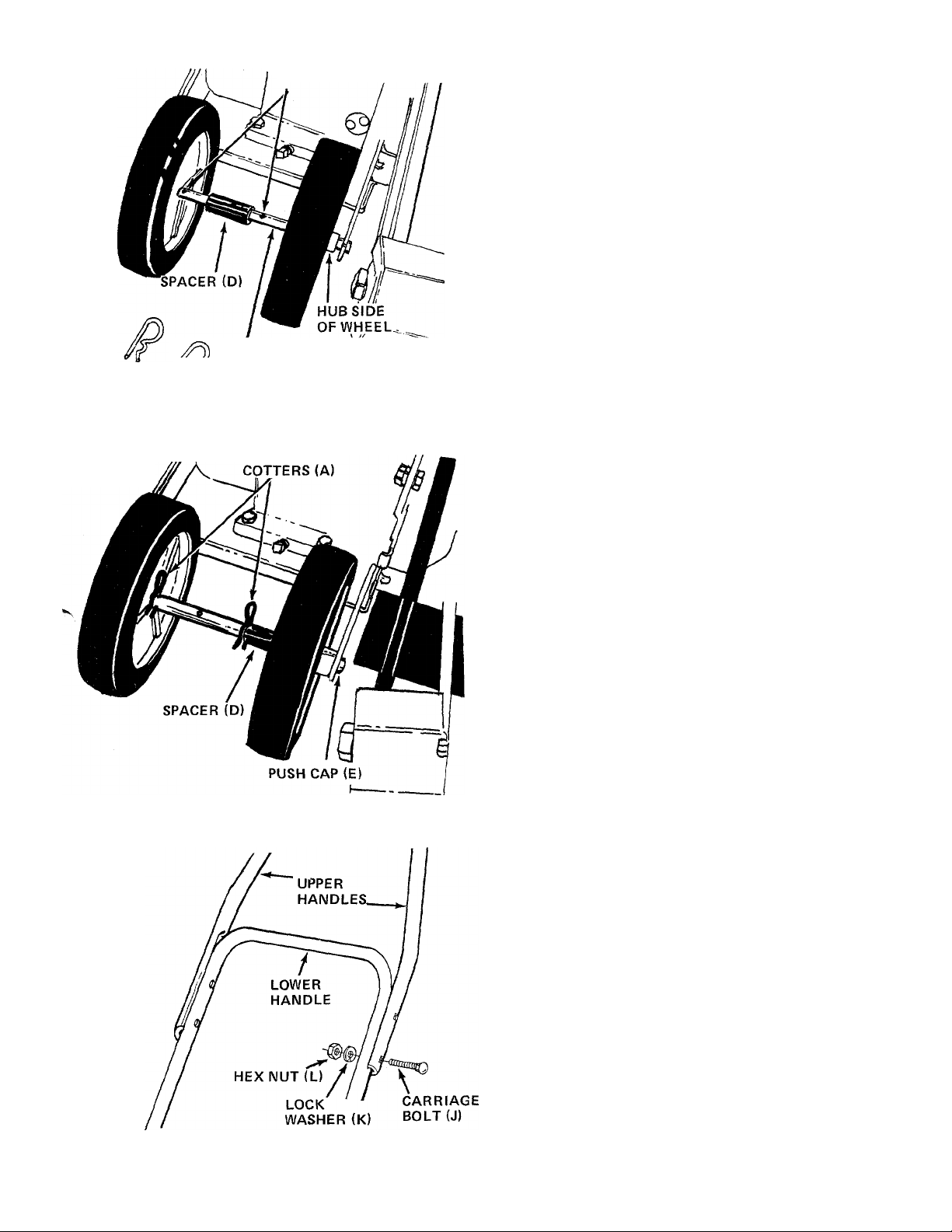
4.
Starting on the right side of the edger, place the
axle through the support arm on the frame. Then
place axle through one wheel so the hub of the
wheel is to the outside of the unit. Next place
axle through spacer (D), the other wheel (hub to
the outside of the unit) and through second
support arm. See figure 4. Secure with push cap
(E) by tapping it on with a hammer. See figure 5.
It is necessary to hold a block of wood or a
second hammer against the push cap on the other
side of the axle.
FIGURE 5
5. Secure the front wheels and axle in position
using two hairpin cotters (A). See figure 5.
Slip the three handle grips (T) on the upper
6.
handles and the engagement handle. They will slip
on more easily if you first soak them in warm,
soapy water.
7.
Assemble the two upper handles to the lower
handle with four carriage bolts (J), lock washers
(K) and hex nuts (L). Tighten only finger tight at
this time. See figure 6.
FIGURE 6
Page 6

FIGURE 7
HEX LOCK NUT (R)
8. Assemble the throttle control to the handle panel
as follows.
A. Hold the throttle control assembly beneath
the handle panel. Turn the control sideways
and insert the lever up through the wide
portion of the slot on the handle panel. See
figure 7A.
B. After the end of the lever is through the slot,
turn and then tip the control forward as shown
in figure 7B to slide it through the slot.
NOTE
The lever must be all the way to the
back of the control housing as shown
in figure 7B.
Push the control back into the slot in the
C.
handle panel and press in place. Be certain the
control is locked securely into the slot. See
figure 7C.
Secure the throttle control to the handle panel
D.
using self-tapping screw (U). See figure 7D.
Place the handle panel over the upper handles and
line up the holes. See figure 8.
FIGURE 8
Secure the right hand side of handle panel with
.10.
two one-inch long hex bolts (S) and hex lock nuts
(R). Do not tighten.
Secure the adjustment bracket to the left hand
11.
side of handle panel with 1-1/4 inch long hex
bolts (Q) and hex lock nuts (R). See figure 8.
12.
Now tighten securely all four bolts and nuts at
handle panel and four bolts and nuts at lower
handle.
13. Place hex bolt (M) through bottom hole in
engagement handle as shown in figure 9, then
through hole in adjustment bracket.
14. Secure hex bolt with compression spring (N), flat
washer (0) and hex lock nut (P) on the inside of
of the adjustment bracket.
15. Secure bent end of clutch rod half to engagement
handle with cotter pin (C). See figure 9.
Page 7

16. Thread rod adjustment link (B) onto the upper
clutch rod half, using about half of the threads.
See figure 10.
17. Thread the lower clutch rod half into the bottom
of the rod adjustment link. See figure 10.
COTTER PIN (C)
SLACK IN BELT
FIGURE 11
CLUTCH ROD
CONTROLS
THROTTLE CONTROL
The throttle control lever is located on the handle
panel. It regulates the engine speed and stops the
engine. See figure 12.
18. Pull the blade and guard assembly all the way back
by hand until there is slack in the belt. See figure
11.
19. Secure the end of the lower clutch rod half to the
arm extension on the pivot bracket with cotter pin
(C). See figure 11.
20. Secure the throttle control cable to handles with
two cable ties (I).
DEPTH CONTROL ADJUSTMENT
The engagement handle controls the clutching and
declutching of the belt. To declutch, the handle is
pulled back toward the operator. The farther forward
the handle is pushed, the deeper the cut. To move the
engagement handle, first move it to the left so the
the handle Is out of the notch. See figure 12.
NOTE
If belt slips when engagement handle
is in the engaged position, lengthen the
clutch rod by turning the rod adjust
ment link. Refer to figure 10.
FIGURE 12
Page 8

BLADE PLANE ADJUSTMENT
The cutting blade can be adjusted to eight positions
from vertical to horizontal. To adjust, release the
adjustment lever on the pivot bracket and rotate the
spindle housing. Place adjustment lever in nctch
desired. See figure 13.
When the blade is adjusted toward the horizontal
position, the front wheels must also be adjus ed.
Remove the two hairpin cotters and slide the specer
and wheel to the right as shown in figure 14. Rein sert
the hairpin cotters.
NOTE
If the wheels are not adjusted, the
blade will hit the left front wheel,
causing the belt to slip.
Become familiar with all the controls and adjustments
before operating the edger so you can adjust it easily
to a variety of cutting and trimming conditions. While
the engine is running, DO NOT ATTEMPT TO MAKE
ANY ADJUSTMENTS except with the throttle
control.
OPERATION
Fill the crankcase with oil using a high quality
detergent oil classified " For Service MS." Nothing
should be added to the recommended oil. SUM
MER - Use SAE 30. WINTER - (Below 40“ F.) Use
SAE 5W-20 or SAE 10W.
Place the engine level. Remove filler plug. FILL
THE OIL SUMP TO POINT OF OVERFLOW.
Pour slowly. See figure 15.
Fill the fuel tank with clean, fresh, lead-free, low-
2.
lead, or regular grade leaded gasoline. DO NOT
MIXOILWITH GASOLINE.
FIGURE 13
SPACER
FIGURE 14
ADJUSTMENT
LEVER
HAIR PIN COTTERS
3. Move the engagement handle (depth control) back
as far as it will go and place in the last notch. See
figure 12.
4. Set the throttle control in "START" position.
5. Pull the choke knob out.
NOTE
A warm engine may not require
choking.
6. Grasp the starter handle and pull out the cord
rapidly. Return it slowly to the engine. If the
engine does not start after two pulls, move the
throttle control to the "FAST" position.
7. After engine starts, push choke knob in gradually.
To stop engine, move throttle control to "STOP"
position. Disconnect spark plug wire and ground to
prevent accidental starting while equipment is un
attended.
Page 9

A
Rotating cutting blade may throw
objects causing personal injury. Always
wear safety glasses or some other
suitable eye protection at all times the
engine is running. Keep area clear of
bystanders and do not operate without
guards in place.
OPERATING THE EDGER
1. Set the adjustment lever (refer to figure 12) in the
second notch at the top to edge vertically. See
figure 16.
CAUTION
3. Move the front wheels all the way to the left when
using the edger on a curb. See figure 18.
FOR USE ON CURBS
FIGURE 18
4. To operate the unit as a trimmer, move the adjust
ment lever and rotate the cutting blade 90°. See
figure 19. Move the front wheels all the way to the
right, as described in the Control section.
FLAT DRIVE
FIGURE 16
2. Set the adjustment lever (refer to figure 13) in the
first notch at the top for trenching. See figure 17.
4>
TRENCHING
FIGURE 17
& c>
CAUTION
A
Do not adjust the blade guard with
the engine running.
r-im
1 1
b__
i-ü
UP TO FENCE, FOUNDATIONS, ETC.
FIGURE 19
'
V'
LUBRICATION
Wheels - The wheels are plastic and require no lubric-
cation.
Engine - Refer to engine manual for lubrication
instructions.
Cutting Head Bearings - The two ball bearings in the
cutting head are lubricated and sealed at the factory
and require no lubrication. Lubricate all other moving
parts with engine oil.
Shaft - Lubricate the two bearings and under the
compression spring on the shaft with light oil at least
once a season. See figure 20.
Page 10

MAINTENANCE
Ac
WARNING {
Disconnect the spark plug wire and
ground against the engine before per
forming any adjustment, repairs or
maintenance.
BLADE REMOVAL
Use a wrench on both sides of the blade when removing
it for replacement.
BELT REMOVAL
1. To remove the V-belt, remove the belt guard
assembly at the engine pulley. Remove the lex
nuts and lock washers. See figure 20.
2. Remove the belt guard at the spindle assembly by
removing two hex bolts, lock washers and hex n jts.
See figure 21.
3. Remove the old belt, and reassemble with a r ew
belt, part number 754-0142.
ENGINE OIL
Check oil level before starting engine and after every
5 hours of operation. Add oil as necessary to keep
level full to point of overflowing. Before removing
plug, clean area around plug to prevent dirt from
entering oil fill opening. Refer to figure 15.
Change oil after first 5 hours of operation. There
after, change every 25 hours. Change oil while engine
is warm. Oil may be drained thru oil drain plug.
Crankcase capacity - 1-1/4 pints.
Refer to engine manual for complete instructions
for care and maintenance of engine.
FIGURE 20
BELT GUARD
BEARINGS
HEX NUTS
AND
LOCK WASH I ;rs
OFF-SEASON STORAGE
The following steps should be taken to prepare unit
for storage.
1. Clean and lubricate unit thoroughly.
2. Refer to engine manual for correct engine storage
instructions.
3. Coat unit's cutting blade with chassis grease to
prevent rusting.
4. Store unit in a dry, clean area.
NOTE
When storing any type of power
equipment in an unventilated or metal
storage shed, care should be taken to
rustproof the equipment. Using a light
oil or silicone, coat the equipment,
especially springs and bearings.
10
Page 11

TROUBLE SHOOTING CHART
PROBLEM CAUSE (S)
1. Engine fails
to start.
2. Hard starting
or loss of power.
3. Engine over
heats.
4. Excessive
vibration at
blade.
5. Belt slips. A. Belt worn or stretched.
6. Blade guard
pivots forward,
throwing dirt on
operator.
A. Check fuel tank for gas.
B. Spark plug lead wire
disconnected.
C. Faulty spark plug.
A. Spark plug wire loose.
B. Dirty air cleaner.
A. Carburetor not adjusted
properly.
B. Air flow restricted.
C. Engine oil level low.
A. Spindle bent.
B. Ball bearings worn out.
B. Clutch handle will not
remain in clutch plate.
Cam lever and carriage
bolt at guard are loose.
CORRECTIVE ACTION(S)
A. Fill tank if empty.
B. Connect lead wire.
C. Spark should jump gap between control electrode and side electrode.
If spark does not jump, replace the spark plug.
A. Connect and tighten spark plug wire.
B. Clean air cleaner as described in engine manual.
A. Adjust carburetor. See engine manual.
B. Remove blower housing on engine and clean as described in the
engine manual.
C. Fill crankcase with the proper oil.
A. Replace spindle.
B. Replace ball bearings.
A. Adjust clutch rod or replace belt.
B. Readjust spring tension at clutch handle.
Readjust guard, tighten cam lever and carriage bolt.
NOTE: For repairs beyond the minor adjustments listed above, please contact your local authorized service dealer.
11
Page 12

Model 604
12
Page 13

Model 604
PARTS LIST FOR MODEL 604 EDGER
REF.
NO.
PART
NO.
COLOR
CODE
1 720-0120 Black Grip
712-0107
2
714-0115
3
4 710-0106
710-0380 Hex Bolt 5/16-18 X 1.75" Lg.*
5
749-0666 Engagement Handle
6
781-0081
7
732-0369
8
736-0264 Fl.-Wash. .344" l.D. x .62" O.D.
9
10 712-0158
747-0498
11
Hex L.-Nut 1/4-20 Thd.
Cotter Pin 1/8" Dia. x 1.00" Lg.*
Hex Bolt 1/4-20 X 1.25" Lg.*
Adjustment Bracket 51 781 -0078
Compression Spring .50" O.D. 52
X 1.38" Lg.
X .063
Hex Cent. L.-Nut 5/16-18 Thd. 56 754-0142 "V"-Belt 3/8" X 31.2" Lg.
Clutch Rod Half 3/8" Dia. x
DESCRIPTION
REF.
NEW
PART
PART
NO.
45 781-0076 Guard Ass'y.
46 781-0080
47
48
49 712-0287
50 736-0329 L.-Wash. 1/4" i.D.*
53
54
55 756-0449
57
NO.
COLOR
CODE
D£SCRIPTION
Edger Blade
712-0287 Hex Nut 1/4-20 Thd.*
736-0329 L.-Wash. 1/4" l.D.*
Hex Nut 1/4-20 Thd.*
Spindle Plate Ass'y.
15319 Bearing Housing 1-3/8" l.D.
741-0155
Ball Bearing .62" l.D. x 1.38" O.D.
710-0258 Hex Bolt 1/4-20 X.62" Lg.*
3/8" "V"-Pulley 2"x 5/8" l.D.
710-0929 Hex Bolt 5/8-18x4.50" Lg.*
18.25" Lg. 58 710-0289 Hex Bolt 1/4-20 x .50" Lg.*
710-0111 Carriage Bolt 1/4-20 x 1.25" Lg.* 59 781-0086
12
13 750-0628
Rod Adjustment Link 60
750-0118 Sleeve ,632" l.D. x .875" O.D.
Beit Guard
14 712-0287 Hex Nut 1/4-20 Thd.* X .90" Lg.
736-0329
15
09955 Lower Handle 62
16
L.-Wash. 1/4" I.D.* 61
712-0267 Hex Nut 5/16-18 Thd.*
736-0242 Bell.-Wash. .345" l.D. x .88" O.D.
17 714-0122 Sq. Key 3/16" x 3/16" x .75" Lg. 63 714-0121 Spring Pin Spir. 1/4" Dia. x 2.00"
18 712-0798 Hex Nut 3/8-16 Thd.*
19 736-0169
L.-Wash. 3/8" I.D.*
20 756-0327 Engine Pulley
750-0212
21
Spacer .75" l.D. 66
22 736-0258 Fl.-Wash. .385" l.D. x 1.0" O.D.
23 710-0152
Hex Bolt 3/8-24 x 1.0" Lg.*
24 734-0841 Rear Wheel Ass'y. 8x1.75
25 738-0108 Shoulder Bolt .498" Dia. x 1.45" Lg. 70
26 13960
Belt Guard Ass'y27 732-0187 Compression Spring
28
711-0379
Bushing
29 712-0267 Hex Nut 5/16-18 Thd.*
30 736-0119 L.-Wash. 5/16" l.D.*
31
715-0247 Spring Pin Spir. 3/16" Dia. x 1.00" 74
Lg.
32
712-0287 Hex Nut 1/4-20 Thd.*
33
736-0112 Bell.-Wash. .535" l.D. x 1.50"O.D.
34
714-0115 Cotter Pin 1/8" Dia. x 1.00" Lg. 77
35
712-0114
36
736-0329 L.-Wash. 1/4" l.D.*
37 781-0087
Hex Slotted Nut 1/2-20 Thd.
Flap Bracket 80 710-0597
38 736-0342 Fl.-Wash. .25"!.D. x .75" O.D. x 81
.030 82
39
710-0289 Hex Bolt 1/4-20 x .50" Lg.* 83 746-0421
40
731-0725 Flap 84 726-0221
41
710-0402
42
750-0229 Spacer .635" l.D. x .88" l.D. x
Hex Bolt 5/16-18x4.5" Lg.*
1.030" Lg.
43
736-0317 Bell.-Wash. .630" i.D. x 1.25" O.D.
44
[ 712-0221
!
_____
Hex Ins. L.-Nut 5/8-18 Thd. 88.
1
64 781-0090
Pivot Bracket Ass'y.
65 710-0600 Hex Wash. Hd. Self Tap Set.
5/16-24 X .50" Lg.
67
781-0075
781-0093 Adjustment Lever Ass'y.
Arm Extension
68 732-0188 Torsion Spring
69 712-0267
736-0119
71
750-0622 Spacer .50"I.D. x.62"O.D. X
Hex Nut5/16-18Thd.*
L.-Wash. 5/16" l.D.*
1.62" Lg.
72 738-0613
Axle .50" Dia. x 8.75" Lg.
(Front)
73 781-0083
Base Ass'y.
714-0101 Hair Pin Cotter 1/2" Dia.
75 710-0442 Hex Bolt 5/16-18 X 1.50"
Lg.*
76
734-0840 Front Wheel Ass'y. 7 x 1.50
Engine
78 726-0192 Cable Tie
79 749-0667 Upper Handle
Hex Bolt 1/4-20 x 1,00" Lg.*
781-0092 Handle Support Plate
831-0692
Throttle Control Box Ass'y.
Throttle Control Wire 30" Lg.
Push Cap 1/2" Dia.
85 711-0386 Spacer .386" l.D. x .510" O.D. x
3.765" Lg.
86
87
89
781-0095
710-0118 Hex Bolt 5/16-18 X .75" Lg. Spec.
711-0699
710-0779
Debris Deflector: .25" Lg.
Stud 1/4-20 X 2.12" Lg.
Self-Tap Scr. #10 x .50" Lg.
NEW
PART
Lg.
*For faster service order standard nuts, bolts, and washers locally. If these items cannot be obtained locally, order by
part number and size as shown on parts list.
(615-Red)
When ordering parts, if color or finish is important, use the appropriate color code shown at left,
(e.g. Red 10112 (615).)
NOTE
This instruction manual covers various models
and all specifications shown do not necessari
ly apply to your model. Specifications subject
to change without notice or obligation.
13
NOTE; The engine is not under warranty by
the edger manufacturer ... if repairs or
service is needed on the engine, please
contact your nearest author- ^^—
ized engine service outlet. Find II Fast
Check the “Yellow Pages” of In The
your telephone book under Yellow Pages
"Engines—Gasoline."
-------------------
---------
Page 14

MTD PRODUCTS INC
...........................................................
P.O. BOX 36900 • CLEVELAND OHIO 44136
VaRD-MaN COMPANY
 Loading...