

Page 1

OWIUERS
MANUAL
.75
tUUtK
ASSEMBLY
OPERATION
MAINTENANCE
PARTS LIST
Important:
Read Safety Rules and
Instructions Carefully
PRINTED IN U.S.A.
Model Numbers
244-595-000
24596L
Thank you for purchasing an
American built product.
FORM NO. 770-3187
Page 2

INDEX
Safe Operation Practices
Assembly Instructions
Operation
Adjustments
Lubrication.................................................................... 8
......................................................................
..................................................................
..............................................
...................................................
4
♦
♦
♦
♦
♦
♦
♦
♦
For one year from the date of original retail purchase, MTD PRODUCTS INC will either
repair or replace, at its option, free Df charge, F.O.B. factory or authorized service firm, any
part or parts found to be defective n material or workmanship. Transportation charges for
the movement of any power equipn ent unit or attachment are the responsibility of the pur
chaser. Transportation charges for any parts submitted for replacement under this warran
ty must be paid by the purchaser ur less such return is requested by MTD PRODUCTS INC.
This warranty will not apply to any part which has become inoperative due to misuse, ex
cessive use, accident, neglect, improper maintenance, alterations, or unless the unit has
been operated and maintained in accordance with the instructions furnished. This warran
ty does not apply to the engine, mo :or, battery, battery chargeror component parts thereof.
Please refer to the applicable man jfacturer’s warranty on these items.
limite;d warranty
3
4
7
7
Maintenance................................................................. 8,
Off-Season Storage ..................................................... ''
Trouble Shooting Chart
Illustrated Parts ...........................................................10
Parts List
.....................................................................
................................................
\
11
4
♦
♦
♦
♦
♦
4
t
♦
♦
♦
♦
This warranty will not apply where the unit has been used commercially.
Warranty service is available throu ih your local authorized service dealer or distributor. If
you do not know the dealer or distributor in your area, please write to the Customer Service
Department of MTD.
The return of a complete unit will not be accepted by the factory unless prior written per
mission has been extended by MTD.
♦
♦
This warranty gives you specific Ingal rights. You may also have other rights which vary
from state to state.
V
WARNING
TO PURCHASERS
OF INTERNAL COMBUSTION ENGINE EQUIPPED
MACHINERY OR DEVICES IN THE STATE OF CALIFORNIA
The equipment which you have just purchesed does not have a spark arrester. If this equipment is used on
any forest covered land, brush covered land, or grass covered unimproved land in the State of California,
before using on such land, the California law requires that a spark arrester be provided. In addition, spark
arrester is required by law to be in effective working order. The spark arrester must be attached to the
exhaust system and comply with Séction 4142 of the California Public Resources Code.
4
4
4
4
4
4
4
Page 3

WARNING
®Tp reduce the potential for any injury, comply with the following safety instructions. Failure to comply with the
structions may result in personal injury.
SAFE OPERATION PRACTICES FOR EDGERS
TRAINING
1. Read this owner's manual carefully in its en
tirety before attempting to assemble or operate
this machine. Be completely familiar with the
controls and the proper use of this machine be
fore operating it. Keep this manual in a safe place
for future and regular reference and for ordering
replacement parts.
2. Your edger is a precision piece of power equip
ment, not a plaything. Therefore, exercise extreme
caution at all times.
3. Never allow children to operate a power edger.
Only persons well acquainted with these rules of
safe operation should be allowed to use your
edger.
4. Keep the area of operation clear of all persons,
particularly small children and pets. Stop engine
when they are in the vicinity of your edger. Al
though the area of operation should be complete
ly cleared of foreign objects, an object may have
been overlooked and could be accidently thrown
by the edger in any direction and cause serious
personal injury to the operator or any others
allowed in the area.
PREPARATION
1. Thoroughly inspect the area where the equip
ment is to be used. Remove all stones, sticks,
wire, bones and other foreign objects which
could be picked up and thrown by the edger in
any direction and cause serious personal injury to
the operator or any others allowed in the area.
2. Do not operate equipment when barefoot or wear
ing open sandals. Always wear substantial foot
wear.
3. Checkthe fuel before starting the engine. Gasoline
is an extremely flammable fuel. Do not fill the
gasoline tank indoors, while the engine is running,
or while the engine is still hot. Wipe off any
spilled gasoline before starting the engine as it
may cause a fire or explosion.
4. Disengage the blade clutch on units so equipped
before starting the engine.
Never attempt to make a wheel adjustment while
the engine is running.
d. Never operate the equipment in wet grass. Always
be sure of your footing. A slip and fall can cause
serious personal injury. Keep a firm hold on the
handle and walk, never run.
OPERATION
1. Never operate this edger unless wearing safety
glasses or some other suitable eye protection at
all times the engine is running.
2. Do not change the engine governor settings or
overspeed the engine.
3. Do not put hands or feet near or under rotating
parts. Keep clear of the discharge opening at all
times as the rotating blade can cause injury.
4. Stop the blade when crossing gravel drives, walks
or roads.
5. After striking a foreign object, stop the engine,
remove the wire from the spark plug, and thor
oughly inspect the edger for any damage. Repair
the damage before restarting and operating the
edger.
6. If the equipment should start to vibrate abnor
mally, stop the engine and check immediately
for the cause. Vibration is generally a warning
of trouble.
7. Stop the engine whenever you leave the equip
ment, before cleaning the guard assembly, and
when making any repairs or inspections.
8. Before cleaning, repairing or inspecting, make
certain the blade and all moving parts have stop
ped. Disconnect the spark plug wire, and keep
the wire away from the spark plug to prevent
accidental starting.
9. Do not run the engine indoors.
10. Shut the engine off and wait until the blade
comes to a complete stop before unclogging
guard assembly.
11. Never operate edger without proper guards, plates
or other safety protective devices in place.
12. Always operate the edger so that the protective
guard guide is positioned between the walk and
the rotating blade. Never allow the rotating blade
to operate directly against concrete walk or drive.
MAINTENANCE AND STORAGE
1. Check the blade and engine mounting bolts at
frequent intervals for proper tightness.
2. Keep all nuts, bolts, and screws tight to be sure
the equipment is in safe working condition.
3. Never store the equipment with gasoline in the
tank inside of a building where fumes may reach
an open flame or spark. Allow the engine to
cool before storing in any enclosure.
4. To reduce fire hazard, keep the engine free of
grass, leaves, or excessive grease.
Page 4
ASSEMBLY
NOTE
.1;
B-
c-
. ^
D-
FIGURE 1
■;> r;
if u
V ■
F-
G-
F-
G-
■im
This unit is shipped WITHOUT GAS
OLINE or OIL. After assembly, see
operating section of this manual for
proper fuel and engine oil recom
mendations.
TOOLS REQUIRED
(1) Adjustable wrench or 3/4" open end or box
wrench
7/16 " open end or box wrench
(2)
" open end or box wrench
9/16
(1)
CONTENTS OF HARDWARE PACK
(See figure 1)
A (3)
Shoulder Bolts 3/8-16 Thread
B (3) Belleville Washers
C (3) Lock Washers
D (3) Hex Nuts 3/8-16 Thread
E
(2) Hex Bolts 1/4-20 x 1 1/4" Long
F
(6) Lock Washers 1/4" I.D.
G (6) Hex Nuts 1/4-20 Thread
H
1
Compression Spring
(1)
(4) Carriage Bolts 1/4-20x 1 1/4" Long
J (2) Cotter Pins
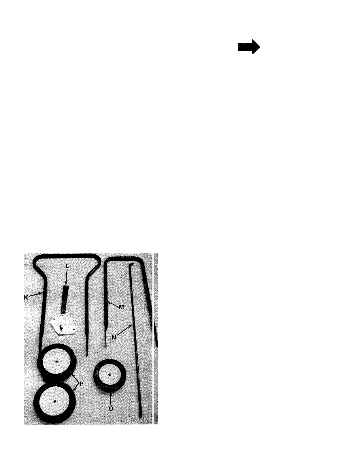
FIGURE 2
»ARTS IN CARTON
— LOO
ISE F
(Seefigure 2)
K
L
M
N
0
P (2)
Upper Handle
(1)
Preassembled Clutch Plate Assembly
(1)
Lower Handle
(1)
Clutch Rod
(1)
Front Wheel 6" Dia.
(1)
Rear Wheels 7" Dia.
Your new edger is shipped preassembled with the_
exception of the handle, rear wheels and front whe
1. Remove the edger and all parts from the carton.
Make certain that all loose parts and literature
are removed from carton before carton is dis
carded.
Page 5

'll
SHOULDER
BOLT (A)
BELLEVILLE
WASHER (B)
FIGURE 3.
1
2. Place lower handle into the slots in the rear
frame. See figure 3.
3. Line up holes in handle with holes in frame.
See figure 3.
LOCKWASHER
(C)\
\ ^
HEX NUT
(D)
4. Secure rear wheels (P) and lower handle (M) to
frame with shoulder bolts (A), belleville washers
(B), lock washers (C) and hex nuts (D). See
figure 3.
FIGURE 4.
LOWER
HANDLE
LOCK WASHER (C)
BELLEVILLE
WASHER (B)
-HEX NUT (D)
Assemble the front wheel (0) as shown in figure
4. Place shoulder bolt (A) through wheel, then
belleville washer (B) (between wheel and frame).
Secure with lock washer tC) and hex nut (D).
See figure 4.
6. Assemble the upper handle (K) to lower handle.
Place the head of carriage bolts (I) to the outside
of handle. Secure with lock washers (F) and
and hex nuts (G). See figure 5.
FIGURES.
Page 6

CLUTCH ROD {h )
NOTE
Right and left hand side is determined
from behind the edger, in the opera
tor's position.
7. Place preassembled clutch plate assembly (L)
on the left hand side of upper handle. Secure
in place with hex bolts (E), lock washers (F)
and hex nuts (G). See figure 6.
FIGURE?.
COMPRESSION
SPRING (H)
SPINDI ^
brack“-
ASSEMBLY
COTTER
PIN(J)
a.
COTTER
PIN IJ)
CLUTCH
LEVER
8. Place compression spring (H) over straight end
of clutch rod (N). Place end of rod in spindle
bracket assembly and secure with cotter pin (J).
See figure 7.
9. Place hook end of clutch rod (N) in clutch
lever. Secure with cotter pin (J). See figure 8.
FIGURES.
CLUTCH
ROD (N)
Page 7

OPERATION
1. Fill the crankcase with oil using a high quality
detergent oil classified "For Service MS". Use
SAE 30 oil. Nothing should be added to the
recommended oil.
Place the engine level. Remove oil fill cap. FILL
THE OIL SUMP TO POINT OF OVERFLOW. Pour
slowly. See figure 9.
CAUTION
A
Never operate this edger unless wear
ing safety glasses or some other suit
able eye protection at all times the
engine is running.
To stop the edger engine, push the grounding clip
against the spark plug. See figure 11.
FIGURE 9.
"X
. Fill the fuel tank with clean, fresh, lead-free,
low-lead or regular grade leaded gasoline. DO
NOT MIX OIL WITH GASOLINE.
3. Pull the choke control out to "choke" position
if necessary. See figure 10.
PULL OUT TO CHOKE
FIGURE 11.
Depth Control Adjustment - The clutching and
declutching of the belt is accomplished by moving
the clutch lever. To declutch, pull the clutch lever
towards you as you operate the edger. The farther
you push the clutch lever forward, the deeper the
cut.
ADJUSTMENTS
WARNING
t
®C
Disconnect the spark plug wire and
ground against the engine before per
forming any adjustments, repairs or
maintenance.
FIGURE 10.
. Grasp the starter handle and pull out the cord
rapidly. Return it slowly to the engine.
5. After engine starts, push choke control in grad
ually.
Front Wheel Adjustment
The front wheel may be raised or lowered to give
added cutting depth.
Loosen the second bolt on the front wheel support
bracket. Pivot the bracket up or down to desired
height. Retighten bolt. See figure 12.
Page 8

SECOND BOLT
FIGURE 12.
WHEEL SUPPORT
BRACKET
LUBRICATION
Engine - Refer to separate engine manual for lu )rica-
tion instructions.
Wheels - The wheels require no lubrication.
Spindle Bearing - The ball bearing in the spindle is
lubricated and sealed at the factory and requires no
lubrication. Lubricate all other moving parts with
engine oil.
%. *
FIGURE 13.
Belt Removal - Remove the spark plug wire and
ground. Remove the gasoline.
1. Tip the edger back so that it rests on the handle.
2. Remove the cotter pin securing the castle nut
on the bottom of belt cover. See figure 14.
MAINTENANCE
\ WARNING
Disconnect the spark plug wire and
ground against the engine before per
forming any adjustments, repairs or
maintenance.
Blade Removal - Hold head of spindle bolt with
a 3/4" or adjustable wrench and remove spindl j nut.
See figure 13.
Engine Oil - Check oil level before starting engine
and after every 5 hours of operation. Add jil as
necessary to keep level full to point of overflowing.
Before removing plug, clean area around plug tj pre
vent dirt from entering oil fill opening.
Change oil after first 5 hours of operation. There
after, change every 25 hours. Change oil while engine
is warm. Oil may be drained thru oil drain plug.
See figure 9. Crankcase capacity - 1 1/4 pints.
COTTER PIN'
BELT COVER'
FIGURE 14.
3. Lift off the hex castle nut, belleville washer and
belt cover. See figure 15.
4. Remove the old belt and replace with new belt.
NOTE
While the belt cover is removed, it is
a good idea to apply a little grease to
the pivot point on belt cover. See
figure 15.
Reassemble thes belt cover, making sure the new
5.
belt is over the engine pulley.
When tightening the castle nut, only tight
6.
enough to line up hole in bolt for cotter pin. DO
NOT OVER TIGHTEN. Belt cover must pivot
freely. See figure 15.
8
Page 9

MOUNTING
BOLT
Set edger back on its wheels. Replace spark plug
wire.
OFF-SEASON STORAGE
The following steps should be taken to prepare unit
for storage.
COTTER PIN
CASTLE NUT
BELLEVILLE
WASHER
FIGURE 15.
1. Clean and lubricate unit thoroughly.
2. Refer to engine manual for correct engine storage
instructions.
3. Coat unit's cutting blade with chassis grease to
prevent rusting.
4. Store unit in a dry, clean area.
When storing any type of power
equipment in an unventilated or metal
storage shed, care should be taken to
rust proof the equipment. Using a
light oil or silicone, coat the equip
ment, especially springs and bearings.
TROUBLE SHOOTING CHART
CAUTION
A
PROBLEM
1. Engine Fails
to start.
2. Hard Starting
or loss of power.
3. Engine Over
heats.
4. Excessive
vibration at
blade.
• 5. Belt Slips.
_____________________
NOTE; For repairs beyond the minor adjustments listed above, please contact your local service dealer.
A. Check fuel tank for gas.
B. Spark plug lead wire,
C. Faulty spark plug.
A. Spark plug wire loose.
B. Dirty air cleaner.
A. Carburetor not adjusted
B. Air flow restricted.
C. Engine oil level low.
A. Spindle bolt bent.
B. Ball bearing worn out.
A. Belt worn or stretched.
B. Cl^utch handle will not
CAUSE
disconnected.
properly.
remain in clutch plate.
REMEDY
A. Fill tank if empty,
B. Connect lead wire.
C. Spark should jump gap between control electrode and side
electrode. If spark does not jump, replace the spark plug.
A. Connect and tighten spark plug wire.
B. Clean air cleaner as described in engine manual.
A. Adjust carburetor. See engine manual.
B. Remove blower housing on engine and clean as described in the
engine manual.
C. Fill crankcase with the proper oil.
A. Replace spindlebelt .
B. Replace ball bearing.
A. Replace bolt.
B. Readjust spring tension at clutch handle.
Page 10

Models 595 and 596
IF YOU WRITE TO US ABOUT THIS ARTICLE
OR IF YOU ORDER REPLACEMENT PARTS AL
WAYS MENTION THIS MODEL & SERIAL NO
MODEL
46
47 4:>
A 3 ^
4J 46
10
Page 11

Models 595 and 596
PARTS LIST FOR MODELS 595 and 596 EDGERS
Ref.
No.
Part
No.
Color
Code
Description
New
Part
Ref.
No.
Part
No.
1 712-0107 Hex Cent. L.-Nut 1/4-20 thd. 37 736-0112
09950
2
3 710-0106 Hex Bolt 1/4-20 X 1.25" Lg.*
4
714-0115
Clutch Plate
Cotter Pin 1/8" Dia. x 1.0"
38 710-0515
39 738-0108
Lg.* 1.450
720-0142 Grip
5
6 09948
7
747-0358
8 732-0171
Clutch Handle Ass'y- X 1.50
Clutch Rod
Compression Spring .50"
O.D. X 1.40" Lg.
736-0264
9
Fl.-Wash. .34" I.D. x .62" 44
O.D. X .063
10 712-0158 Hex Cent. L-Nut 5/16-18 Thd.
11
12 714-0105
13 710-0938
14
710-0442
711-0421 Engine Pulley
15
08253
16
736-0242
17
Engine
Sq.Key 3/16 x 1.0" Lg.*
SetScr. 1/4-28 x 1/4" Lg.
Hex Bolt 5/16-18 X 1.50'^' Lg.*
Bearing Housing
Bell.-Wash. .34'^ I.D. x 88"
O.D. X .060
710-0528
18
09954
19
20 736-0112
Hex Bolt 5/16-18 X 1.25" Lg.*
Blade
Bell.-Wash. .535" I.D. x 1.50"
40
734-0840 Wheel Ass'y. Comp. 6" Dia.
41
736-0169
42
712-0267
43 736-0119
712-0798
45 13332
46
736-0105 Bell.-Wash. .400" I.D. x 88"
710-0623
47
48
738-0108 Shoulder Bolt .498" Dia. x
49
734-0839 Wheel Ass'y. Comp. 7" Dia.
736-0105
50
749-0453
51
710-0111
52
O.D. X .052
21 712-0239
22 736-0112
Hex Cent. L.-Nut 1/2-20 Thd.
Bell.-Wash. .535" I.D. x 1.50"
O.D. X .052
23
24
711-0564
732-0330
Spacer
Compression Spring .57"
0 D. X 1.92" Lg.
25
736-0112
Bell.-Wash. .535" I.D. x
1.50" O.D. X .052
26
27
28
29
30
712-0114
711-0716
726-0111
09952
748-0298
Hex Castle Nut 1/2-20 Thd.
Shoulder Spacer
Push Cap
Guide
Spacer .354" I.D. x .635"
O.D. X .510" Lg.
14341 - 497 Blade Guard Ass'y.
31
32
33
34
35
36
741-0919
13333 - 497
736-0119
712-0267
756-0361
Ball Bearing .IQT' I.D.
X 1.85" O.D. X .551
Spindle Bracket Ass'y-
L-Wash. 5/16" I.D.* O.D. X.060
Hex Nut 5/16-18 Thd.
Pulley
53 749-0452
54 736-0329
712-0287
55
736-0169
56
712-0798
57
13330 - 497
58
714-0115
59
754-0142
60
712-0267
61
62 736-0119
718-0144
63
64 14427
711-0720
65
731-0532
66
710-0380
67
736-0272
69
710-0116
70
Color
Code
Description
Bell.-Wash. .535" I.D. x 1.50"
O.D. X .052
Hex Bolt 1/2-20x3.50" Lg.*
Shoulder Bolt .498" Dia. x
L-Wash. 3/8" I.D.*
Hex Nut 5/16-18 Thd.*
L-Wash. 5/16" I.D.*
Hex Nut 3/8-16 Thd.*
Front Wheel Support
O.D. X .060
Hex Wash. Hd. Self Tap Scr.
3/8-16 X .75" Lg.
1.450
X 1.50
Bell.-Wash. .400" I.D. x 88"
O.D.
Lower Handle
Carriage Bolt 1/4-20 x 1.25"
Lg.*
Upper Handle
L-Wash. 1/4" I.D. *
Hex Nut 1/4-20 Thd.*
L-Wash. 3/8" I.D.*
Hex Nut 3/8-16 Thd.*
Base Ass'y.
Cotter Pin 1/8" Dia. x 1.0"
Lg-*
3V-Belt31.2" Lg.
Hex Nut 5/16-18 Thd.*
L-Wash. 5/16" I.D.*
Grip (Optional)
Flap Bracket
Hinge Pin
Debris Deflector
Hex Bolt 5/16-18 X 1.75"
Lg.*
Fl.-Wash. .51 I.D. x 1.00
Hex Bolt 5/16-18x2.00"
Lg.*
New
Part
*For faster service obtain standard nuts,
size as shown or parts list.
The engine is not under warranty by the edger manufacturer. If repairs or service is needed on the
engine, please contact your nearest authorized engine service outlet. Check the “Yellow Pages" of
your telephone book under “Engines — Gasoline.”
bolts and washers locally. If these items cannot be obtained localjy, order by part number and
Find It Fast
In The
Yellow Pages
11
Page 12

PARTS; INFORMATION
POWER EQUIPMENT PARTS AND SERVICE
Parts and service are available through the authorized sjrvice
firms listed below. All orders should specify the model numoerof
your unit, part numbers, description of parts and the quan ity of
each part required.
NOTE: If any parts are found to be missing or cefective upon assembly of this unit, write to advise the factory so
that immediate replacement can be mac e.
ALABAMA BiRMiNGHAM
Auto Electric & Carburetor Co. . . . 2625 4th Ave. S
...........
ARKANSAS NORTH LiTTLE ROCK
Sutton’s Lawn Mower Shop
...........
5301 Roundtop Drive
Box 368, Rt. 4
............
CALiFORNiA PORTERVILLE
Billious
..................
........................
75 North D Street ....
COLORADO DENVER
Spitzer Industrial Products Co. .. . 6601 N.
Washington St............
FLORIDA JACKSONVILLE
Radco Distributors.......................... 4909 Victor St.
Box 5459 ...................
OPA LOCKA
Small Eng. Dist
..............................
2351 N.W. 147th St. ..
GEORGIA EAST POINT
East Point Cycle & Key
.................
2834 Church St
............
ILLINOIS LYONS
Keen Edge Co
.......................................
8615 Ogden Ave.........
INDIANA ELKHART
Parts & Sales Inc
........................
2101 Industrial Pkwy..
IOWA DUBUQUE
Power Lawn & Garden Equip
........
2551 J.F. Kennedy ...
LOUISIANA MONROE
Mid-South Power
...........................
1500 Arkansas St. ...
NEW ORLEANS
Suhren Engine Co
MARYLAND TAKOMA PARK
Center Supply Co
................................
...........................
6867 New Hampshire
8330 Earhart Blvd. .. .
Ave
.............................
MASSACHUSETTS SPRINGFIELD
Morton B. Collins Co
...................
300 Birnie Ave
...............
MICHIGAN LANSING
Lorenz Service Co
......................
2500 S. Pennsylvania .
MOUNT CLEMENS
Power Equipment Dist
...................
340 Hubbard
...............
MINNESOTA HOPKINS
Hance Distributing Inc
.................
420 Excelsior Ave. W.
MISSISSIPPI BILOXI
Biloxi Sales & Service, Inc
.............
506 Caillavet St
..........
MISSOURI KANSAS CITY
Automotive Equip. Service
.............
3117 Hoimes St
..........
ST. JOSEPH
Ross-Frazier Suppiy Co
................
8th and Monterey
ST. LOUIS
Henzier, Inc.................................2015 Lemay Ferry Rd.
NEW JERSEY BELLMAWR
Lawnmower Parts Inc
....................
717 Creek Rd
................
NEW MEXICO ALBUQUERQUE
Spitzer Eng. & Parts
......................
1023 Third Ave. N.W. .
NEW YORK CARTHAGE
Gamble Dist., Inc
Red Fox Parts Dist
.........................
........................
West End Ave
SCHOHARIE
..............
Rt. 30 P.O. Box 527 .. ..
35233 Smith Hardware Co.............................515 N. George St
72117 OHIO CARROLL
93257 CLEVELAND
80229 National Central
32207 Box 929
33054 Victory Motors, Inc
30344, Kenton Supply Co
60534 EECOInc
46516 Thompson Rubber Co
52001 BluemontCo..........................................11125 Frankstown Rd.. 15235
71201 Frank Roberts & Sons ........................R.D. 2..............................15767
70118 Scranton Auto Ignition Co
20912 MEMPHIS
01107 TEXAS DALLAS
48910 FORT WORTH
48043 HOUSTON
55343 SAN ANTONIO
39533 P.O. Box 17867
64109 A-1 Engine & Mower Co....................... 439E.900So
64503 RBI Corp...............................................101 Cedar Run Dr
..........
63125 Bailey’s Inc
08030 Automotive Supply Co..........................123 S. Linwood Ave.
87103 CHILTON
13619
12157
BRIGGS AND STRATTON, TECUMSEH AND PEERLESS PARTS
AND SERVICE
Briggs & Stratton, Tecumseh and Peerless parts and servic'
should be handled by your nearest authorized engine service firri
Check the yellow pages of your telephone directory under the
listing Engines—Gasoline, Briggs & Stratton or Tecumseh
Lauson.
NORTH CAROLINA GOLDSBORO
Dixie Sales Company
Stebe’s Mid-State Mower Supply . Box 366, 71 High St... .43112
Bleckrie, Inc....................................... 7900 Lorain Ave
Burton Supply Co
OKLAHOMA MUSKOGEE
OREGON PORTLAND
PENNSYLVANIA HARRISBURG
..............................................
TENNESSEE KNOXVILLE
Master Repair Service
American Sales & Service, Inc. ... 3035-43 Bellbrook ....38116
Marr Brothers, Inc............................... 423 E. Jefferson
Woodson Sales Corp
Bullard Supply Co
Engine House Inc
UTAH SALT LAKE CITY
VIRGINIA ASHLAND
WASHINGTON SEATTLE
...........................................
WISCONSIN APPLETON
Horst. Dist........................................... 444 N. Madison
........................
..................................
..............................
...............................
...............................
..........................
....................
......................
.........................
.............................
...............................
GREENSBORO
335 N. Green
WADSWORTH
687 Seville Rd
YOUNGSTOWN
1301 Logan Ave.
605 S. Cherokee
8216 N. Denver Ave. .. .97217
4021 N.6thSt
PHILADELPHIA
5222-24 N. Fifth St
PITTSBURGH
PUNXSUTAWNEY
SCRANTON
1133-35 Wyoming Ave. 18509
2000 Western Ave
1702 N. Sylvania
2409 Commerce St. ... 77003
8610 Botts Lane
1414 14th Ave
P.O. Box 798
.................
...............
.........................
................
.................
...............
................
...........
..............
..........
.......
........
...........
..........
...........
.........
............
27530
27402
44102
44281
44501
74401
17110
19120
379,'
75203
76111
78217
84111
23005
98122
54911
53014
WARRANT' PARTS AND SERVICE POLICY
(0483)
The purpose of warranty is to protect the customer fror defects in workmanship and materials, defects which are NOT detected at the
time of manufacture. It does not provide for the unlimitiid and unrestricted replacement of parts. Use and maintenance are the respon
sibility of the customer. The manufacturer cannot assu ne responsibility for conditions over which it has no control. Simply put, if it’s
the manufacturer’s fault, it’s the manufacturer’s respons ibility; if it’s the customer’s fauit, it’s the customers’s responsibility.
CLAIMS AGAINST THE MANUFACTURER’S WARRANT’'
INCLUDES:
1. Replacement of Missing Parts on new equipment.
2. Replacement of Defective Parts within the warranty jeriod.
3. Repair of Defects within the warranty period.
All claims MUST be substantiated with the following
information:
1. Model Number of unit involved.
2. Date unit was purchased or first put into service.
3. Date of failure.
4. Nature of failure.
MTD PRODUCTS INC
P.O. BOX 36900
CLEVELAND, OHIO 44136
 Loading...