

Page 1
OWNErS GUIDE
OUTDOOR POWER EQUIPMENT
for all seasons
2 H.R
EDGER
$1.00
Model Numbers
248-596-000
24596-8
IMPORTANT:
Read Safety Rules and Instructions Carefully
PRINTED IN U.S.A. FORM NO. 770-5200C
Thank you for purchasing
an American-built product.
Page 2

NDEX
Safe Operation Practices
Assembly Instructions
Operation ......................................
Adjustments ..................................
Lubrication.....................................
..............
...................
..............................
.......................... . 4
..................... 7
...................... . . 7
...................
i
. 8 Renlacement Parts List
Instructions given with this symbol are
for personal safety. Be sure to follow
them.
Maintenance
3
Off-Season Storage
Troube Shooting Chart
1 llustrated Parts
.......................................
.............................
........................
.................................
.......................
.................... 8
.................... 9
.................... 9
....................10
....................11
AC WARNING {
This unit is equipped with an internal combust on engine and should not be used on or near any unimproved
forest-covered, brush-covered or grass-covered land unless the engine's exhaust system is equipped with a
spark arrester meeting applicable local or state aws (if any). If a spark arrester is used, it should be maintained
in effective working order by the operator.
In the State of California the above is required by law (Section 4442 of the California Public Resources Code).
Other states may have similar laws. Federal la\i/s apply on federal lands. A spark arrester muffler is available
through your nearest engine authorized service center.
Page 3

WARNING
A
t
To reduce the potential for any injury, comply with the following safety instructions. Failure to comply with the
/•“^structions may result in personal injury.
t
SAFE OPERATION PRACTICES FOR EDGERS
TRAINING
1. Read this owner's manual carefully in its en
tirety before attempting to assemble or operate
this machine. Be completely familiar with the
controls and the proper use of this machine be
fore operating it. Keep this manual in a safe place
for future and regular reference and for ordering
replacement parts.
2. Your edger is a precision piece of power equip
ment, not a plaything. Therefore, exercise extreme
caution at all times.
3. Never allow children to operate a power edger.
Only persons well acquainted with these rules of
safe operation should be allowed to use your
edger.
4. Keep the area of operation clear of all persons,
particularly small children and pets. Stop engine
when they are in the vicinity of your edger. Al
though the area of operation should be complete
ly cleared of foreign objects, an object may have
been overlooked and could be accidently thrown
by the edger in any direction and cause serious
personal injury to the operator or any others
allowed in the area.
. No one should operate this unit while intoxicated
or while taking medication that impairs the senses
or reactions.
PREPARATION
1. Thoroughly inspect the area where the equip
ment is to be used. Remove all stones, sticks,
wire, bones and other foreign objects which
could be picked up and thrown by the edger in
any direction and cause serious personal injury to
the operator or any others allowed in the area.
2. Do not operate equipment when barefoot or wear
ing open sandals. Always wear substantial foot
wear.
3. Check the fuel before starting the engine. Gasoline
is an extremely flammable fuel. Do not fill the
gasoline tank indoors, while the engine is running,
or while the engine is still hot. Wipe off any
spilled gasoline before starting the engine as it
may cause a fire or explosion.
4. Disengage the blade clutch on units so equipped
before starting the engine.
Never attempt to make a wheel adjustment while
the engine is running.
d. Never operate the equipment in wet grass. Always
be sure of your footing. A slip and fall can cause
serious personal injury. Keep a firm hold on the
handle and walk, never run.
OPERATION
1. Never operate this edger unless wearing safety
glasses or some other suitable eye protection at
all times the engine is running.
2. Do not change the engine governor settings or
overspeed the engine.
3. Do not put hands or feet near or under rotating
parts. Keep clear of the discharge opening at all
times as the rotating blade can cause injury.
4. Stop the blade when crossing gravel drives, walks
or roads.
5. After striking a foreign object, stop the engine,
remove the wire from the spark plug, and thor
oughly inspect the edger for any damage. Repair
the damage before restarting and operating the
edger.
6. If the equipment should start to vibrate abnor
mally, stop the engine and check immediately
for the cause. Vibration is generally a warning
of trouble.
7. Stop the engine whenever you leave the equip
ment, before cleaning the guard assembly, and
when making any repairs or inspections.
8. Before cleaning, repairing or inspecting, make
certain the blade and all moving parts have stop
ped. Disconnect the spark plug wire, and keep
the wire away from the spark plug to prevent
accidental starting.
9. Do not run the engine indoors.
10. Shut the engine off and wait until the blade
comes to a complete stop before unclogging
guard assembly.
11. Never operate edger without proper guards, plates
or other safety protective devices in place.
12. Always operate the edger so that the protective
guard guide is positioned between the walk and
the rotating blade. Never allow the rotating blade
to operate directly against concrete walk or drive.
MAINTENANCE AND STORAGE
1. Check the blade and engine mounting bolts at
frequent intervals for proper tightness.
2. Keep all nuts, bolts, and screws tight to be sure
the equipment is in safe working condition.
3. Never store the equipment with gasoline in the
tank inside of a building where fumes may reach
an open flame or spark. Allow the engine to
cool before storing in any enclosure.
4. To reduce fire hazard, keep the engine free of
grass, leaves, or excessive grease.
Page 4
NOTE
ASSEMBLY
This unit is shipped WITHOUT GAS
OLINE or OIL. After- assembly, see
operating section of this manual for
proper fuel and engine oil recom
mendations.
o o o
FIGURE 1
^—•
K-
LM-
NOTE
Right and left hand side is determined
from behind the edger, in the opera
tor's position.
TOOLS REQUIRED
(1) Adjustable wrench or 3/4" open end or box
wrench
(2) 7/16" open end or box wrench
(1) 9/16" open end or box wrench
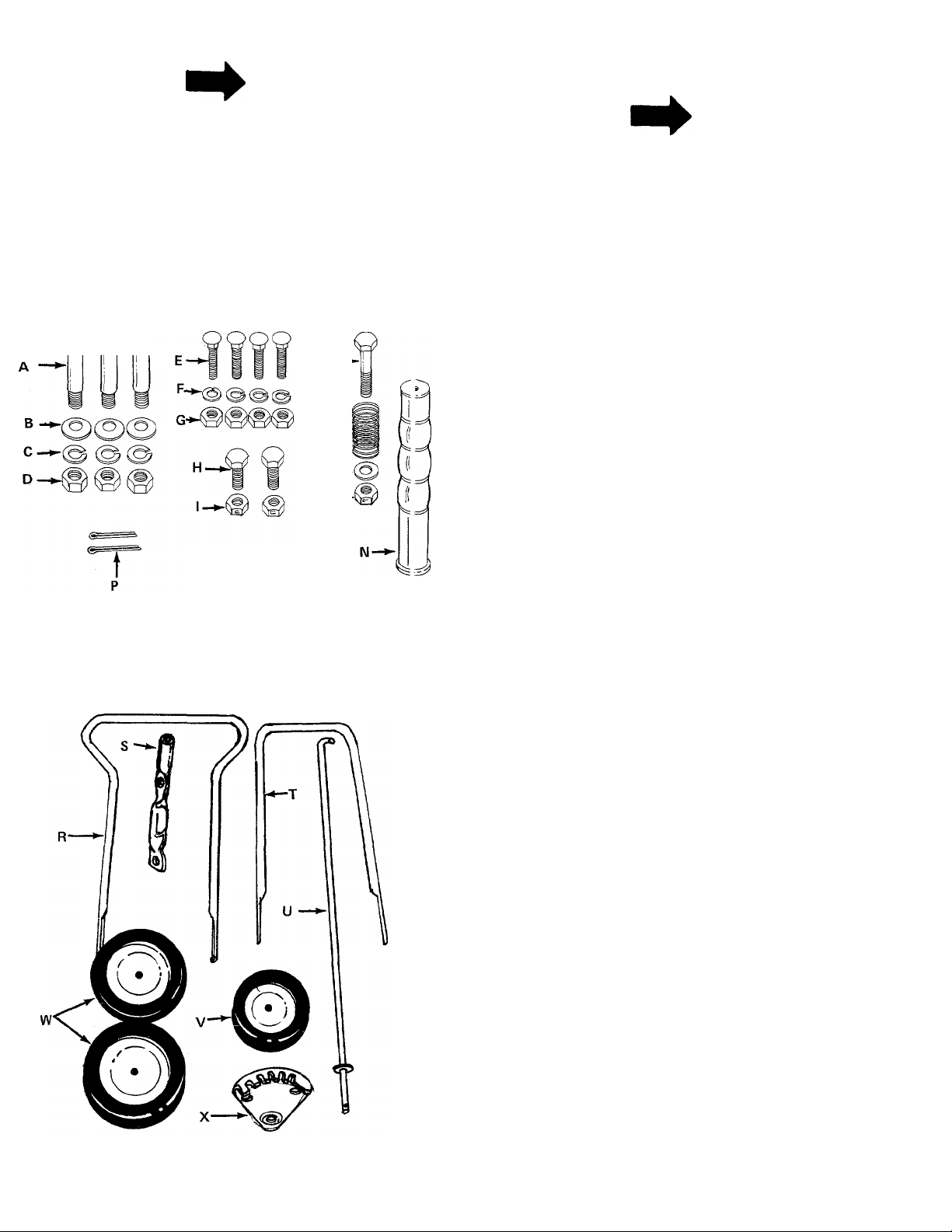
CONTENTS OF HARDWARE PACK
■> (See figure 1)
A
B
C
D
E
F
G
H
1
J
K
L
M
N
0
P
Shoulder Bolts 3/8-16 Thread
(3)
Belleville Washers 3/8" I.D.
(3)
Lock Washers 3/8" I.D.
(3)
Hex Nuts 3/8-16 Thread
(3)
Carriage Bolts 1/4-20 x 1 1/4" Long
(4)
Lock Washers 1/4" I.D.
(4)
Hex Nuts 1/4-20 Thread
(4)
Hex Bolts 1/4-20 X 1 1/4" Long
(2)
Hex Lock Nuts 1/4-20 Thread
(2)
Hex Bolt 5/16-18 X 1 3/4" Long
(1)
Compression Spring 1 3/8" Long
(1)
Flat Washer 5/16" I.D.
(1)
Hex Lock Nut 5/16-18 Thread
(1)
Grip
(1)
Compression Spring 2" Long
(1)
Cotter Pins
(2)
FIGURE 2
LOOSE PARTS IN CARTON
(Seefigure 2)
R
S
T
u
V
w
X
Your new edger is shipped preassembled with the
exception of the handle, rear wheels and front whe "“
1. Remove the edger and all parts from the carto.
Upper Handle
(1)
Clutch Handle
(1)
Lower Handle
(1)
Clutch Rod
(1)
Front Wheel 6" Dia.
(1)
Rear Wheels 7" Dia.
(2)
Clutch Plate
(1)
Make certain that all loose parts and literature
are removed from carton before carton is dis
carded.
Page 5

..aNDLE through
SLOT IN FRAME
SHOULDER
BOLT (A)
BELLEVILLE
WASHER (B)
FIGURES.
HEX NUT (D)
+
LOCK
WASHER (C)
BELLEVILLE
WASHER (B)
2. Place lower handle into the slots in the rear
frame. See figure 3.
3. Line up holes in handle with holes in frame.
See figure 3.
4. Secure rear wheels (W) and lower handle (T) to
frame with shoulder bolts (A), belleville washers
(B) (cupped side of washer against the frame),
lock washers (C) and hex nuts (D). See figure 3.
FRONT
WHEEL
5. Assemble the front wheel (O) toward the inside
of the unit as shown in figure 4. Place shoulder
bolt (A) through wheel, then belleville washer (B)
(between wheel and frame, cupped side against
the frame). Secure with lock washer (C) and hex
nut (D). See figure 4.
FIGURE 4.
LOCK WASHER (C)
HEX NUT,
(D)
6. Assemble the upper handle (R) to lower handle.
Place the head of carriage bolts (E)to the outside
of handle. Secure with lock washers (F) and
and hex nuts (G). See figure 5.
Page 6

HEX LOCK-T
NUT (M)
FIGURE?
7. Place clutch plate (X) on the left hand side of the
upper handle as shown in figure 6. Secure in
place with hex bolts (H) and hex lock nuts (I).
CLL TCH
ROD (U)
8. Place hex bolt (J) through bottom hole in clutch
handle as shown in figure 7, then through hole in
adjustment bracket.
9. Secure hex bolt with compression spring (K),
fiat washer (L) and hex lock nut (M) on the inside
of the adjiistment bracket.
HEX BOLT U)
COMPRESSION
SPRING (K)
10. Place compression spring (0) over straight end
of clutch rod (U). Place end of rod in spindle
bracket assembly and secure with cotter pin (P).
See figure 8.
11. Secure bent end of clutch rod to clutch handle
with cotter pin (P). See figure 7.
12. Slip the handle grip (N) on the end of the clutch
handle. It will slip on more easily if it is firs
soaked in warm, soapy water.
Page 7

OPERATION
Fill the crankcase with oil using a high quality
detergent oil classified "For Service MS". Use
SAE 30 oil. Nothing should be added to the
recommended oil.
Place the engine level. Remove oil fill cap. FILL
THE OIL SUMP TO POINT OF OVERFLOW. Pour
slowly. See figure 9.
A
Rotating cutting blade may throw
objects causing personal injury. Always
wear safety glasses or some other
suitable eye protection at ail times the
engine is running. Keep area clear of
bystanders and do not operate without
guards in place.
To stop the edger engine, push the grounding clip
against the spark plug. See figure 11.
CAUTION
Fill the fuel tank with clean, fresh, lead-free,
low-lead or regular grade leaded gasoline. DO
NOT MIX OIL WITH GASOLINE.
3. Pull the choke control out to CHOKE position if
necessary. See figure 10.
FIGURE 10
Grasp the starter handle and pull out the cord
rapidly. Return it slowly to the engine.
5. After engine starts, push choke control in grad
ually.
FIGURE 11
Depth Control Adjustment - The clutch handle
controls the clutching and declutching of the belt. To
declutch, the handle is pulled back toward the
operator. To move the clutch handle, first move it to
the left so the handle is out of the notch.
NOTE
The full range of depth positions for the
edger may not be available until the belt
has stretched with use.
ADJUSTMENTS
WARNING
A(
Disconnect the spark plug wire and
ground against the engine before per
forming any adjustments, repairs or
maintenance.
Front Wheel Adjustment
The front wheel may be raised or lowered to give
added cutting depth.
Loosen the second bolt on the front wheel support
bracket. Pivot the bracket up or down to desired
height. Retighten bolt. See figure 12.
t
Page 8

SECOND
BOLT
WHEEL
SUPPORT
BRACKET
FIGURE 12
LUBRICATION
Engine - Refer to separate engine manual for lubiication instructions.
Wheels - The wheels require no lubrication.
Spindle Bearing - The ball bearing in the spind e is
lubricated and sealed at the factory and require: no
lubrication. Lubricate all other moving parts v/ith
engine oil.
MAINTENANCE
A |*WARN*NG
FIGURE 13
Belt Removal - Remove the spark plug wire and
ground. Remove the gasoline.
1. Tip the edger back so that it rests on the handle.
2. Remove the cotter pin securing the castle nut
on the bottom of belt cover. See figure 14.
Disconnect the spark plug wire and
ground against the engine before per
forming any adjustments, repairs or
maintenance.
Blade Removal - Hold head of spindle bolt \/ith
a 3/4" or adjustable wrench and remove spindle iut.
See figure 13.
Engine Oil - Check oil level before starting enjine
and after every 5 hours of operation. Add oi as
necessary to keep level full to point of overflowing.
Before removing plug, clean area around plug to pre
vent dirt from entering oil fill opening.
Change oil after first 5 hours of operation. There
after, change every 25 hours. Change oil while engine
is warm. Oil may be drained thru oil drain plug.
See figure 9. Crankcase capacity - 1 1/4 pints.
FIGURE 14
3. Lift off the hex castle nut, belleville washer and
belt cover. See figure 15.
4. Remove the old belt and replace with new belt.
NOTE
While the belt cover is removed, it is
a good idea to apply a little grease to
the pivot point on belt cover. See
figure 15.
5. Reassemble the belt cover, making sure the new
belt is over the engine pulley.
6. When tightening the castle nut, only tightt.,
enough to line up hole in bolt for cotter pin. DO
NOT OVERTIGHTEN. Belt cover must pivot
freely. See figure 15.
Page 9

7. Set edger back on its wheels. Replace spark plug
wire.
OFF-SEASON STORAGE
The following steps should be taken to prepare unit
for storage.
1. Clean and lubricate unit thoroughly.
2. Refer to engine manual for correct engine storage
instructions.
3. Coat unit's cutting blade with chassis grease to
prevent rusting.
4. Store unit in a dry, clean area.
NOTE
When storing any type of power
equipment in an unventilated or metal
storage shed, care should be taken to
rustproof the equipment. Using a
light oil or silicone, coat the equip
ment, especially springs and bearings.
FIGURE 15
PROBLEM CAUSE
Engine fails
1.
to start.
Hard starting
2.
or loss of power.
3.
Engine over
heats.
4. Excessive
vibration at
blade.
B. Spark plug lead wire
C. Faulty spark plug.
B. Dirty air cleaner. B. Clean air cleaner as described in engine manual.
A. Carburetor not adjusted
B. Air flow restricted.
C. Engine oil level low.
A. Spindle bolt bent.
B. Ball bearing worn out.
TROUBLE SHOOTING CHART
A. Check fuel tank for gas. A. Fill tank if empty.
B. Connect lead wire.
disconnected.
C. Clean, adjust gap or replace.
A. Spark plug wire loose.
properly.
A. Connect and tighten spark plug wire.
A. Adjust carburetor. See engine manual.
B. Remove blower housing on engine and clean as described in the
engine manual.
C. Fill crankcase with the proper oil.
A. Replace spindle belt.
B. Replace ball bearing.
REMEDY
Belt slips.
L_
__
NOTE: For repairs beyond the minor adjustments listed above, please contact your local service dealer.
A. Belt worn or stretched. A. Replace belt.
B. Clutch handle will not
remain in clutch plate.
B. Readjust spring tension at clutch handle.
Page 10

H
^96
^43
9q
To
^ J
Page 11

Models 596 and 24596
PARTS LIST FOR MODEL 596 EDGER
PART
COLOR
NO.
1 712-0107
781-0081
2
3 710-0106
4
714-0115
5 720-0120
6 749-0666
7 747-0358
8
732-0369
CODE
DESCRIPTION
NEW
’ART
PART
NO.
REF.
Hex Cent. L.-Nut 1/4-20Thd. 37 736-0112 Bell.-Wash. .535" I.D. x 1.50"
Clutch Plate O.D. X .052
Hex Bolt 1/4-20 x 1.25" Lg.* 38 710-0515 Hex Bolt 1/2-20 X 3.50" Lg.*
Cotter Pin 1/8" Dia. x 1.0" 39 738-0108 Shoulder Bolt .498" Dia. x
Lg.*
Grip 40 734-1175 Wheel Ass'y. Comp. 6" Dia.
Clutch Handle
Clutch Rod
41
736-0169 L.-Wash. 3/8" I.D.*
Compression Spring .50" 42 712-0267
NO.
COLOR
CODE
DESCRIPTION
1.450
x 1.50
Hex Nut 5/16-18 Thd.*
O.D. X 1.38" Lg. 43 736-0119 L-Wash. 5/16" I.D.*
736-0264 Fl.-Wash. .34” I.D. x .62” 44 712-0798
9
10
712-0158
O.D. X .063
Hex Cent. L.-Nut 5/16-18 Thd. 46
45 13332 Front Wheel Support
736-0105 Bell.-Wash. .400" I.D. x 88"
11 Engine
12
714-0105
13 710-0938
14
710-0442
711-0421
15
16 08253
736-0242
17
710-0528
18
09954 Blade
19
736-0112
20
Sq.Key 3/16 x 1.0” Lg.* 47
SetScr. 1/4-28 x 1/4" Lg.
Hex Bolt 5/16-18 X 1.50'^' Lg.*
Engine Pulley
Bearing Housing
Bell.-Wash. .34" I.D. x 88"
O.D. X .060
Hex Bolt 5/16-18 X 1.25" Lg.*
Bell.-Wash. .535" I.D. x 1.50"
710-0623
48
738-0108
49
734-1176 Wheel Ass'y. Comp. 7" Dia.
50 736-0105
749-0453
51
710-0111
52
O.D. X .052
21 712-0239
736-0112
Hex Cent. L.-Nut 1/2-20 Thd.
Bell.-Wash. .535" I.D. x 1.50"
O.D. x .052
23 711-0564
732-0330
24
Spacer
Compression Spring .57"
0 D X 1 92" Lq.
25
736-0112
Bell.-Wash. .535" I.D. x
1.50" O.D. X .052
26
27
28
29
30
712-0114
711-0716
796-0111
П9952
748-0298
Hex Castle Nut 1/2-20 Thd.
Shoulder Spacer
Push Cap
Guide
Spacer .354" I.D. x .635"
O.D. X .510" Lg.
14341 -638 Blade Guard Ass'y.
31
741-0919
32
13333
33
34 736-0119
712-0267
35
756-0361
36
■‘For faster service order standard nuts, bolts, and washers locally. If these items cannot be obtained locally, order by part number and
size as shown on parts list.
638-MTD Red
621—Brilliant Firemist (24596)
Ball Bearing .787" I.D.
X 1.85" O.D. X.551
Spindle Bracket Ass'y-
L-Wash. 5/16" I.D.* O.D. X .060
Hex Nut 5/16-18 Thd. 70
Pulley
When ordering parts, if color or finish is important, use the appropriate color code shown at left,
[i.e. (part no.) - 638 for MTD Red finish].
53 749-0452
54 736-0329
712-0287
55
736-0169
56
57 712-0798
1333U
58
59
60
61
62
63
64
65
66
67
69
714-0115
754-0142
712-0267
736-0119
718-0144
14427
711-0720
731-0532
710-0380
736-0272
- 638'
710-0116
Hex Nut 3/8-16 Thd.*
O.D. X .060
Hex Wash. Hd. Self Tap Scr.
3/8-16 X .75" Lg.
Shoulder Bolt .498" Dia. x
1.450
X 1.50
Bell.-Wash. .400" I.D. x 88"
O.D.
Lower Handle
Carriage Bolt 1/4-20 x 1.25"
Lg.*
Upper Handle
L-Wash. 1/4" I.D. *
Hex Nut 1/4-20 Thd.*
L-Wash. 3/8" I.D.*
Hex Nut 3/8-16 Thd.*
Base Ass y.
Cotter Pin 1/8" Dia. x 1.0"
Lg.*
3V-Belt31.2" Lg.
Hex Nut 5/16-18 Thd.*
L-Wash. 5/16" I.D.*
Grip (Optional)
Flap Bracket
Hinge Pin
Debris Deflector
Hex Bolt 5/16-18 X 1.75"
Lg.*
Fl.-Wash. .51 I.D. x 1.00
Hex Bolt 5/16-18x2.00"
Lg.*
NEW
PART
The engine is not under warranty by theedger manufacturer. If repairs or service is needed on the
engine, please contactyour nearest authorized engine service outlet. Check the "Yellow Pages" of
your telephone book under "Engines — Gasoline."
11
Find It Fast
In The
Yellow Pages
Page 12

REPLACEMENT PARTS • P.O. JOX 36900 • CLEVELAND, OHIO 44136
 Loading...