

Page 1
OUTDOOR POWER EQUIPMENT
for all seasons
.75
POWER
VACUUM
Important:
Read Safety Rules and
Instructions Carefully
PRINTED IN U.S.A.
Model Numbers
245-660-000
24665S
Thank you for purchasing
an American-built product.
J
FORM NO. 770-3976
Page 2

INDEX
Safe Operation Practices.............................................. 3
Assembly Instructions .................................................. 4
Operation
Adjustments .... ...............................................
...
............................................................. 7
8
Instri ctions given with this symbol are
for p( rsonal safety. Be sure you follow
A
them,
LIMITED WARRANTY
For one year from the date of original retail purchase, MTD PRODUCTS INC will either
repair or replace, at its option, free of charge, F.O.B. factory or authorized service firm, any
part or parts found to be defective i n material or workmanship. Transportation charges for
the movement of any power equipment unit or attachment are the responsibility of the pur
chaser. Transportation charges for any parts submitted for replacement under this warran
ty must be paid by the purchaser un ess such return is requested by MTD PRODUCTS INC.
This warranty will not apply to any oart which has become inoperative due to misuse, ex
cessive use, accident, neglect, improper maintenance, alterations, or unless the unit has
been operated and maintained in ac cordance with the instructions furnished. This warran
ty does not apply to the engine, mot or, battery, battery chargeror component parts thereof.
Please refer to the applicable manufacturer’s warranty on these items.
Maintenance
Illustrated Parts
Replacement Parts List
.................
..............
8
1C
11
This warranty will not apply where the unit has been used commercially.
Warranty service is available throuc h your local authorized service dealer or distributor. If
you do not know the dealer or distril>utor in your area, please write to the Customer Service
Department of MTD.
The return of a complete unit will not be accepted by the factory unless prior written per
mission has been extended by MTD.
This warranty gives you specific legal rights. You may also have other rights which vary
from state to state.
I WARNING I
This unit is equipped with an internal combustion engine and should not be used on or near any unimproved forestcovered, brush-covered or grass-covered land ur less the engine's exhaust system is equipped with a spark arrester
meeting applicable local or state laws (if any). If < spark arrester is used, it should be maintained in effective workin"
order by the operator.
In the State of California the above is required by law (Section 4442 of the California Public Resources Code).
Other states may have similar laws. Federal laws apply on federal lands. A spark arrester muffler is available at
your nearest engine authorized service center.
2
Page 3

A
It is suggested that this manual be read in its entirety before attempting to assemble or operate. Keep this manual
in a safe place for future reference and for ordering replacement parts.
This unit is shipped WITHOUT GASOLINE or OIL. After assembly, see separate engine manual for proper fuel
and engine oil recommendations.
IMPORTANT
SAFE OPERATION PRACTICES FOR POWER VACUUMS
1. Read this operating and service instructing manual
carefully. Be thoroughly familiar with the controls
and proper use of the power vacuum.
2. Never allow children to operate this power
vacuum.
3. Keep the area of operation clear of all persons,
particularly small children and pets.
4. No one should operate this unit while intoxicated
V or while taking medication that impairs the senses
or reactions.
5. Check fuel before starting engine. Do not fill fuel
tank indoors, when engine is running, or while
engine is hot. Wipe off any spilled fuel before
starting engine.
6. Do not change engine governor settings.
7. Do not put hands near rotating parts for any
reason.
8. If the power vacuum should start to vibrate
abnormally, stop the engine and check immedi
ately for the cause. Vibration is generally a
vyarning of trouble.
9. Before cleaning, repairing or inspecting, make
certain all moving parts have come to a complete
stop. Disconnect spark plug wire and keep wire
away from plug to prevent accidental starting.
Also keep throttle control lever in the stop
position.
10. If the power vacuum should become blocked with
debris at any point, shut engine off and wait
until the impeller comes to a complete stop
before attempting to remove the obstruction.
Disconnect spark plug wire to prevent accidental
starting.
11. Check all bolts for tightness at frequent periods.
12. Never store this power vacuum with fuel in the
tank. Allow engine to cool before storing in any
enclosure.
13. Never operate this power vacuum unless air duct
and vacuum bag are properly affixed in their
place. Large zippered end of bag must be closed
when operating to prevent objects from being
blown out.
13. Keep bag and equipment free of debris when not
in use.
15. Never empty vacuum bag when engine is running.
16. Never change auxiliary hose attachment when
engine is running.
17. The manufacturer recommends that the operator
wear safety glasses or some other suitable eye
protection when operating this machine.
18. Check the vacuum bag frequently for wear and
replace when necessary.
Page 4
ASSEMBLY INSTRUCTIONS
TOOLS REQUIRED:
(2) 9/16" Wrenches
(2) 7/16" Wrenches
(1) Hammer or Rubber Mallet
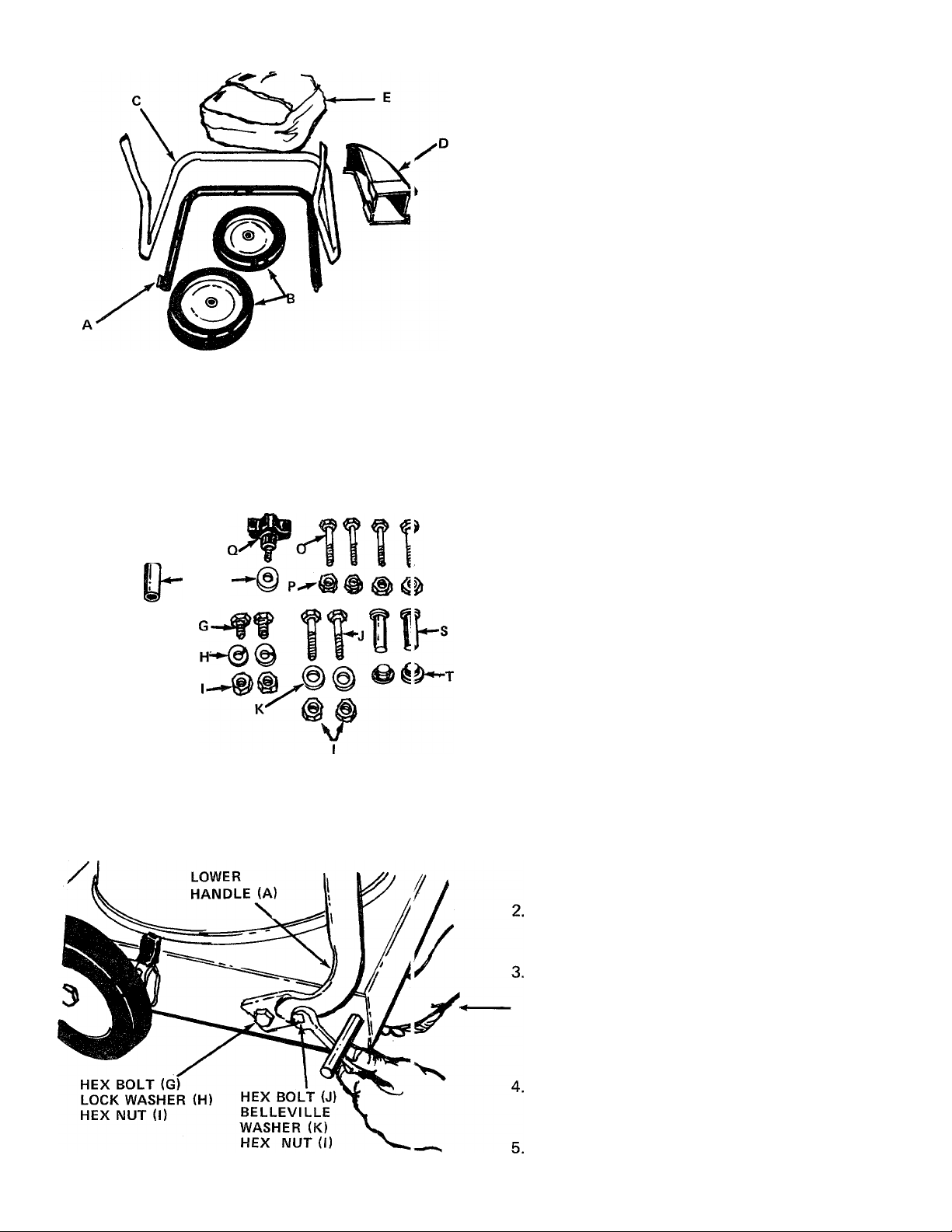
LOOSE PARTS IN CARTON (See figure 1):
FIGURE 1
# t>-'
V
W1
L R
A
B (2)
C
D
E
CONTENTS OF HARDWARE PACK (See figure 2):
G (2) Hex Bolts 3/8-16 x 3/4" Long
H (2) Lock Washers 3/8" I.D.
I (4) Hex Nuts 3/8-16 Thread
J (2) Hex Bolts 3/8-16 X 1-1/2" Long
-K (2) Belleville Washers 3/8" I.D. X 1-1/8" O.D.
L (2) Spacers 1/2" I.D. x 15/16" Long
M (4) Flat Washers 1/2" I.D. X 1" O.D.
N (2) Black Push Caps
O (4) Hex Bolts 1/4-20 x 1-3/4" Long
P (4) Hex Lock Nuts 1/4-20 Thread
Q (1) Thumb Screw 5/16-18 Thread
R (1) Belleville Washer 5/16" I.D. X 7/8" O.D.
S (2) Stud Pins
T (2) Push-On Speed Nuts
Lower Handle
(1)
Rear Wheels
Upper Handle
(1)
Air Duct Assembly
(1)
Bag
(1)
FIGURE 2
FIGURE 3
1.
Remove the vacuum, loose parts, hardware pack
and literature from the carton. Make certain all
parts and literature have been removed before
the carton is discarded.
Raise the back of the unit off the floor approxi
mately 3 inches and block it so that the lower
handle and rear wheels may be assembled.
Place lower handle (A) in position on the vacuum,
lining up the holes in the handle with the holes
on the frame. See figure 3. Place hex bolts (G)
(3/4" long) through lower hole in handle and
frame. Secure with lock washers (H) and hex
nuts (I) on the inside of frame, finger tight only.
Place hex bolts (J) through upper hole in hand'
and frame. Secure with belleville washers (K
(cupped side against the frame) and hex nuts (I).
Tighten all four nuts and bolts using two 9/16"
wrenches.
Page 5

SPACER (L)
FIGURE 4
AXLE
SHAFT
Slide spacers (L) onto the axle shafts. Place one
flat washer (M) on each shaft next to the spacers.
See figure 4.
FLAT
WASHER (M)
Place rear wheels in position on the shafts, then
another flat washer (M). Secure with black push
cap (N) by placing the push cap in position and
tapping on with hammer or rubber mallet. See
figure 5.
FIGURE 5
FIGURE 6
PUSH
CAP (N)
UPPER HANDLE
Place the upper handle (C) in position over lower
handle. Fasten with four hex bolts (0) and hex
lock nuts (P) provided. See figure 6. Two
7/16" wrenches are required.
LOWER
HANDLE
Page 6

9. Place the stud pins (S) in holes in upper handle
(head of pins go to the inside of handle). Secure
pins with push-on speed nuts (T) by holding
speed nut with box wrench and tapping pin with
hammer. See figure 7.
10. Place the tabs on the air duct assembly (D) into
the slots in the frame as shown in figure 8. Raise
the air duct into position.
FIGURES
THUMB
SCREW (Q)
11. Secure air duct with thumb screw (Q) and belleville washers (R). Cupped side of washer must be
against the air duct. See figure 9.
Page 7

12. Assemble the bag (E) by slipping the top straps
on the bag over upper handle. Hook the two
small straps over the stud pins on handle. See
figure 10.
13. Slip the elastic opening of the bag over the ak
duct assembly, making certain the elastic opening
is secured behind the flanges on all four sides of
on the air duct. See figure 11.
FLANGE ON’
AIR DUCT ASSEMBLY
FIGURE 11
OPERATION
BEFORE STARTING
Service engine with gas and oil. See engine manual
packed with vacuum for complete instructions for
care and maintenance of engine. READ DIREC
TIONS CAREFULLY.
CAUTION
A
Revolving Blades - Keep hands and
feet away from all openings.
TO START ENGINE
After the engine has been properly fueled and oiled
(refer to engine operating and maintenance instruc
tions), start engine as follows.
1. Move throttle control lever on engine to START
position.
2. Crank engine. Pull recoil with quick firm pull.
Do not pull out so far the rope stops with a jerk
as this will cause rope failure. Do not allow rope
and handle to snap back into place.
3. After two or three full firm pulls on recoil (or as
soon as engine fires), move speed control to RUN
position.
TO STOP ENGINE
1. move throttle control lever to
To stop engine,
STOP position.
2. Disconnect spark plug wire and ground to prevent
accidental starting while equipment is unattended.
Operate a new engine at intermediate speeds and light
load for the first few hours as you would a new
automotive engine.
Page 8

The bag may be emptied using the large zipper as
shown in figure 12. Be certain the zipper is closed
when operating the unit.
FIGURE 12.
CARBURETOR ADJUSTMENT
^ WARNING )
A
If any adjustments are made to the
engine while the engine is running
(e.g. carburetor), disengage all clutch
es. Keep clear of all moving parts. Be
careful of heated surfaces and muffler.
If carburetor needs adjustment to start or for operatidn, see "Carburetor Adjustment" section of engine
manual.
MAINTENANCE
ADJUSTMENTS
CAUTION
Ai
Do not at any time make any adjust
ment to the unit without first stopping
engine and disconnecting spark plug
wire.
HEIGHT ADJUSTMENT
An adjusting plate and thumb lever at both Tont
wheels provide height adjustment for the vacjum.
See figure 13. Each adjusting plate has nine posilions.
Height will be changed when the thumb lever is
moved from one position to another. Simply dearess
thumb lever towards wheel and move wheel and lever
assembly to desired position. Both wheels mu ;t be
placed in the same relative position. Lower the 'ront
of the unit to obtain more suction.
A |*VarnÎng*J
Disconnect spark plug wire and ground
it against the engine before performing
any repairs or maintenance.
BAG
Under normal usage the bag is subject to wear, anc
should be checked periodically. Be sure any re
placement complies with the manufacturer's recom
mendation. Wash bag periodically with water.
Allow to dry thoroughly in the shade. Do not use
heat.
ENGINE
Refer to engine manual for proper maintenance
procedures. Follow instructions carefully.
OFF-SEASON STORAGE
The following steps should be taken to prepare the
vacuum for storage.
1. Clean the engine and the entire unit thoroughly.
2. Refer to engine manual for correct engine storage
instructions.
3. Store in a clean, dry area.
NOTE
When storing any type of power
equipment in an unventilated or metal
storage shed, care should be taken to
rust proof the equipment. Using a
light oil or silicone, coat the equip
ment especially all moving parts.
Page 9

TROUBLE SHOOTING CHART
PROBLEM
1. Engine fails to
to start.
2. Hard starting or
loss of power.
3. Engine over
heats.
4. Excessive
vibration.
NOTE: For repairs beyond the minor adjustments listed above, please contact your local authorized service dealer.
A. Check fuel tank for gas.
B. Spark plug lead wire
C. Faulty spark plug.
A. Spark plug wire loose.
B. Dirty air cleaner.
A. Carburetor not adjusted
B. Air flow restricted.
C. Engine oil level low.
A. Bent crankshaft.
B. Impeller assembly out
CAUSE REMEDY
A. Fill tank if empty.
disconnected.
properly.
of balance.
B. Connect lead wire.
C. Spark should jump gap between control electrode and side
electrode. If spark does not jump, replace the spark plug.
A. Connect and tighten spark plug wire.
B. Clean air cleaner as described in engine manual.
A. Adjust carburetor. See engine manual.
B. Remove blower housing on engine and clean as described in the
engine manual.
C. Fill crankcase with the proper oil.
A. Replace crankshaft {should be done by an authorized service
dealer).
B. Replace impeller assembly.
Hose Attachment Kit Model 295-210-000 and Blower Conversion Kit Model 295-211-000
are available as optional equipment.
Page 10

Model 660 and 24665
IF YOU WRITE TO US ABOUT THIS ARTICLE
OR IF YOU ORDER REPLACEMENT PARTS AL
WAYS MENTION THIS MODEL & SERIAL NO
MODEL
10
Page 11

Model 660 and 24665
PARTS LIST FOR MODEL 660 POWER VACUUM
^Ref.
No.
1 749-0664
749-0480
2
710-0260
3
Part
No.
Color
Code
Description
Upper Handle (Painted!
Upper Handle (Chrome)
Engine
Carriage Bolt 5/16-18 x .62" Lg.!^
4 15784 -- 488 Blower Housing Ass'y.
5
6
7
8
710-0654
15786
736-0217
710-0591
Hex Tap Scr. 3/8-16 x 1.00" Lg.,
Impeller Ass'y.
L.-Wash. 3/8" I.D.*
Hex Bolt 3/8-24 X 1.0" Lg. 32
w/Patch
g
723-0137
P.V.C. Foam Strip (4-Pcs. 12"
Lg.)
15780 -488
10
15796
11
12 15788
15790
13
14 728-0123
735-0222
15
712-0267
16
736-0242
17
738-0102
18
Vacuum Deck Ass'y.
Front Baffle Ass'y. 36
Lower Baffle Ass'y.
Wiper Retaining Strip
Pop Rivet .188" Dia.
Nozzle Wiper Rear 40
Hex Nut 5/16-18 Thd.*
Bell.-Wash..34"I.D. x.87"O.D.
ShId. Bolt 1/2" Dia. x 1.45"
Lg. (3/8-16)
. 19
734-1139
Wheel Ass'y. Comp. 8 x 1.75"
- Front
20
736-0331
Bell.-Wash. .39" I.D. x 1.12"
O.D.
21
22
23
15262
¿15261
736-0331
Wheel Pivot Bar
Index Plate
Bell.-Wash. .39" I.D. x 1.12"
O.D.
24
25
26
712-0798
14832
738-0507
Hex Nut 3/8-16 Thd.*
Spring Lever Ass'y. w/Knob
Shoulder Bolt .500" x 7/16"
Lg. (3/8-16)
27 726-0128
Push Cap .50" Rod (Black)
New
Part
N
Ref.
No.
736-0272
28
734-1140 Wheel Ass'y. Comp. 10 x 1.75"
29
Part
No.
Color
Code
Description
Fl.-Wash. 1/2" I.D. x 1.0" O.D.
X .06
- Rear
736-0272
30
750-0588 Wheel Spacer 1/2" I.D. x 15/16'
31
Fl.-Wash. 1/2" I.D. x 1.0" O.D.
X .06
Lg.
736-0331
Bell.-Wash. .39" I.D. x 1.12"
O.D.
33
34
35
712-0798
15779
710-0201
Hex Nut 3/8-16 Thd.*
Air Duct Ass'y.
Hex Bolt 3/8-16 X .75" Lg.*
710-0344 Hex Bolt 3/8-16 X 1.50" Lg.*
37 736-0242
720-0170
38
712-0107
39
712-0113
41
710-0136
764-0208 Vacuum Bag (6.6 Bushel)
42
749-0592
43
749-0665
Bell.-Wash. .34" I.D. x.87" O.D.
Thumb Scr. 5/16-18 x .75" Lg.
Hex Cent. L.-Nut 1/4-20 Thd.
Wing Nut 1/4-20 (Plastic)
Hex Bolt 1/4-20X 1.75" Lg.*
Lower Handle (Painted)
Lower Handle (Chrome)
44 14578 Height Adjuster Ass'y. Comp. -
R.H.
14579 Height Adjuster Ass'y. Comp -
L.H. (Not Shown)
45 1539-019 Push Speed Nut .25" Dia.
711-0737
46
47 714-0105
735-0221 Nozzle Wiper Side
48
Stud Pin .250" Dia. X 1.75" Lg.
Sq. Key 3/16 x 3/16 x 1.00" Lg.
49 15789 Wiper Retaining Strip
710-0302
50
Hex Wash. Hd. ”F" Tap Scr.
#10
51 736-0169
L-Wash. 3/8" I.D.*
New
Part
N
*For faster service obtain standard nuts, bolts and washers
locally. If these items cannot be obtained locally, order by
part number and size as shown on parts list.
(488 - Mack Truck Yellow)
(615- Red)
When ordering parts, if color or finish is important use the
appropriate color code shown above, (e.g. Mack Truck
Finish - 14542 (488).)
NOTE: The engine is not under warranty by the vacuum manufacturer ... If repairs or service is needed
on the engine, please contact your nearest authorized engine service outlet. Check the "Yellow Pages" of
your telephone book under "Engines - Gasoline."
This instruction manual covers various models and
all specifications shown do not necessarily apply
to your model. Specifications subject to change
without notice or obligation.
NOTE
11
Find II Fast
■ In The
Yellow Pages
Page 12

MTD PRODUCTS INC
................
............................
VaRD-Man COMPANY
P.O. BOX 3690C
CLEVELAND OHIO 44136
 Loading...