

Page 1
YaRD-MaN
OUTDOOR POWER EQUIPMENT
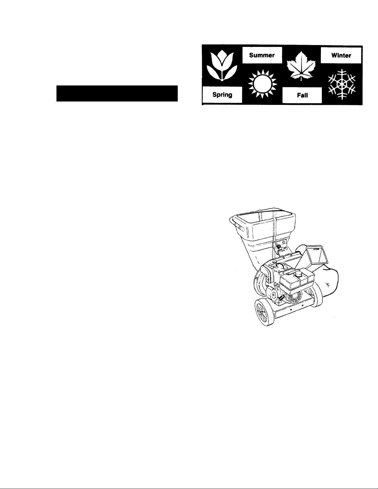
for all seasons
Owner’s
8H.P.
SHREDDER
Manual
ASSEMBLY
OPERATION
MAINTENANCE
IMPORTANT:
Read Safety Rules and
Thank you for purchasing an American-built product.
Model Number
Instructions Carefully
WARNING: This unit is equipped with an internai combustion engine and shouid not be used on or near any unimproved for
est-covered, brush-covered or grass-covered iand uniess the engine’s exhaust system is equipped with a spark arrester
meeting appiicable iocai or state iaws (if any). If a spark arrester is used, it should be mairitained in effective working order
by the operator.
In the State of California the above is required by law (Section 4442 of the California Public Resources Code). Other states
may have similar laws. Federal laws apply on federal lands. A spark arrester for the muffler is available through your nearest
engine authorized service dealer or contact sen/ice department, P.O. Box 368022, Cleveland, Ohio 44136-9722.
PRINTED IN U.S.A.
244-648D401
FORM NO. 770-8607J
Page 2

A
S>VFETY RULES
WARNING: TO REDUCE THE POTENTIAL FOR ANY INJURY, COMPLY WITH THE FOLLOWING
SAFETY INSTRUCTIONS. FAILURE TO COMPLY WITH THE INSTRUCTIONS MAY RESULT IN
PERSONAL INJURY.
TRAINING
• Read this owner’s manual carefully in its entir« ty before
attempting to assemble or operate this machine Be com
pletely familiar with the controls and the propsr use of
this machine before operating it. Keep this me nual in a
safe place for future and regular reference and for order
ing replacement parts.
• Children must never be allowed to operate tf is equip
ment.
• No one should operate this unit while intoxicated or while
taking medication that impairs the senses or rea Dtions.
• This equipment should never be operated in tt le vicinity
of children, pets or other persons.
• Never run your machine in an enclosed area as the
exhaust from the engine contains carbon monoxi de, which
is an odorless, tasteless and deadly poisonous g as.
• Never place your hands or any part of your bod;' or cloth
ing inside the feeding chamber, discharge chut i, or near
any moving part while the machine or engine is unning.
• If it is necessary for any reason to inspect or epair the
feeding chamber or any part of the machine whe re a mov
ing part can come in contact with your body oi clothing,
stop the machine, allow it to cool, disconnect :he spark
plug wire from the spark plug and move it awa^ from the
spark plug before attempting such inspection or repair.
PREPARATION
• Wear safety glasses provided with your unit whi e operat
ing the shredder to prevent injury from any mate rial which
may be ejected out of the openings.
• Wear proper apparel. Avoid wearing loose fittinc clothing.
Wear gloves when handling material.
• HANDLE GASOLINE WITH CARE as it is an extremely
flammable fuel.
• Check the fuel before starting the engine. Do t lot fill the
fuel tank indoors, while the engine is running, or while the
engine is still hot. Turn the unit off and let the er gine cool
before refueling.
• Fuel your shredder in a clean area. Do not smoh e while
refueling.
• Fuel tank cap must be secure at all times excepi during
refueling.
• Avoid spilling gasoline or oil. Wipe the unit clean of any
spilled fuel or oil.
• Store fuel and oil in approved containers, away 1 rom heat
or open flame, and out of reach of children.
• This machine should be operated only upon a le /el sur
face.
• Assure that all screws, nuts and bolts and other ;asteners
are properly secured.
OPERATION
• When feeding shreddable material into this e(|uipment,
be extremely careful that pieces of metal, rock;, bottles,
cans or other foreign objects are not included. Personal
injury or damage to the machine could result.
• If the cutting mechanism strikes any foreign object or if
your machine should start making an unusual noise or
vibration, immediately stop the engine, disconnect the
spark plug wire from the spark plug and move it away
from the spark plug. Allow the machine to stop and take
the following steps:
Inspect for damage.
Replace or repair any damaged parts.
Check for any loose parts and tighten to assure continued
safe operation.
• The engine must be kept clean of debris and other accu
mulations.
• Do not allow an accumulation of processed material to
build up in the discharge area as this will prevent proper
discharge and can result in kick-back from feed opening.
• Never place your hands or any other part of your body or
clothing inside the feeding chamber, discharge chute or
near any moving part while the engine is running.
• Keep all guards and deflectors in place and in good work
ing condition to assure continued safe operation.
• Always stand clear of the discharge area when operating
this machine.
• Keep your face and body back from the feed opening to
avoid accidental bounce back of any material.
• Do not over-reach. Keep proper balance and footing at all
times.
• The engine governor settings on your machine must not
be altered, changed, or tampered with. The governor
controls the maximum safe operating speeds and pro
tects the engine and all moving parts from damage
caused by overspeed.
• Do not transport machine while engine is running.
• Do not operate engine if air cleaner or cover directly over
carburetor air intake is removed, except for adjustment.
Removal of such parts could create a fire hazard.
MAINTENANCE AND STORAGE
• When this equipment is stopped for servicing, inspection,
storage or to change an accessory, make sure the spark
plug wire is disconnected from the spark plug and moved
away from the spark plug. The machine should be
allowed to cool down before making such inspection,
adjustments, service, etc. Maintain your machine with
care and keep it clean for the best and continued safe
operation.
• Do not use flammable solutions to clean the air filter.
• When not in use, your machine should be stored out of
the reach of children. Keep where gasoline fumes will not
reach an open flame or spark. For long periods of stor
age, refer to the “Off-Season Storage” section of this
manual.
Page 3
ASSEMBLY INSTRUCTIONS
N
IMPORTANT: This unit is shipped WITHOUT GASO
LINE or OIL. After assembly, see operation section of
this manual for proper fuel and engine oil recommen
dations.
NOTE: To determine right and left hand sides of your
chipper-shredder, stand behind and face the hopper
(engine is at the front of the unit).
Your chipper-shredder has been completely assem
bled at the factory, except for the chute deflector and
the catcher bag. A pair of safety glasses are also
included in the carton.
TO REMOVE CHIPPER-SHREDDER FROM CARTON
Cut the corners of the carton. Remove all packing
inserts. Roll chipper-shredder out of the carton. Make
certain all parts, literature and the safety glasses have
been removed before the carton is discarded.
TOOLS REQUIRED FOR ASSEMBLY
(2) 7/16" or Adjustable Wrenches
Spacers
(Inside^
Hinge)'
FIGURE 1.
Hex Bolt
Chute
Deflector
HOW TO SET-UP YOUR CHIPPER-SHREDDER
WARNING: Make certain the spark plug
wire is disconnected and moved away
A
from the spark plug before assembling
the chipper-shredder.
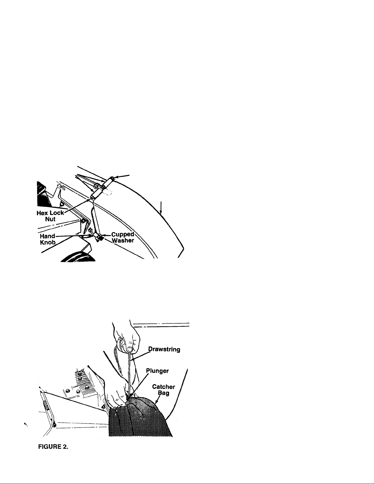
AHACHING THE CHUTE DEFLECTOR
1. Remove the hand knobs and cupped washers
from each side of the discharge opening on the
left side of the shredder.
2. Remove the hex lock nut, two spacers and hex
bolt from inside the hinge on top of the discharge
opening. Do not remove one spacer from the hex
bolt.
3. Place the chute deflector in position on the dis
charge opening. Insert bolt through hinge on chute
deflector and housing (spacer fits inside hinge).
4. Place second spacer over the hex bolt, inside the
other part of hinge. Secure with hex lock nut.
Tighten securely.
5. Secure both sides of the chute deflector to the
housing using hand knobs and cupped washers
(cupped side of washers go against chute deflec
tor).
AHACHING THE CATCHER BAG
Your chipper-shredder is equipped with a catcher bag
to catch the shredded material.
To attach bag, place bag opening over the chute
deflector so it completely covers chute opening.
Depress plunger on drawstring, pull on drawstring
until bag is tight around chute opening. Release
plunger to lock it into position. See figure 2.
Page 4
I I
OPERATION
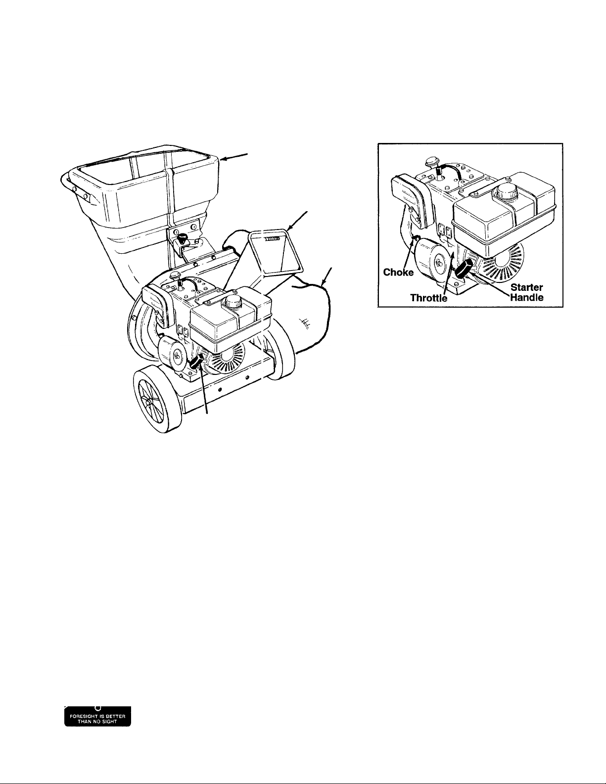
KNOW YOUR SHREODER
READ THIS OWNER’S MANUAL AND SAFliTY RULES BEFORE OPERATING YOUR SHREDDER. Compare
the illustrations with your shredder to familiarize yourself with the location of various controls and adjustments.
Save this manual for future reference.
Ho pper
Chipper
Chute
Catcher
Bag
Starter
Handle
FIGURE 3.
OPERATING CONTROLS (See figure 3 and 1)
RELEASE HANDLE—Used to release the hopper
when lowering to the ground.
CHOKE LEVER—Used to enrich the fuel n ixture in
the carburetor when starting a cold engine.
STARTER HANDLE—Used to manually start the
engine.
THROTTLE CONTROL—Controls engine sp eed and
stops the engine.
The operation of any shredder can result in for
eign objects being thrown into the eyeri, which
can result in severe eye damage.
Always wear safety glasses or eye
shields. We recommend wide
^ ' vision safety mask for ovei specta
cles or standard safety glasses.
FIGURE 4.
BEFORE STARTING
1. Place the shredder on a firm, level surface.
2. Attach spark plug wire to spark plug.
3. Service engine with gasoline and oil as instructed
in the separate engine manual packed with your
shredder.
4. Open fuel shut-off valve (if so equipped).
NOTE: Check the fuel level periodically to avoid run
ning out of gasoline while operating the chippershredder. If the unit runs out of gas as it is shredding
or chipping, it may be necessary to unclog the unit
before it can be restarted. Refer to “Removing the
Flail Screen” on page 7.
TO START ENGINE
WARNING: Be sure no one other than the
operator is standing near the shredder
A
while starting or operating.
Page 5

Place the throttle control lever in FAST position.
1.
See figure 4.
N
Move choke lever to CHOKE position (a warm
2.
engine may not require choking).
Grasp starter handle (see figure 4) and pull rope
out slowly until engine reaches start of compres
sion cycle (rope will pull slightly harder at this
point). Let the rope rewind slowly.
Pull rope with a rapid, continuous, full arm stroke.
4.
Keep a firm grip on starter handle. Let rope
rewind slowly. Do not let starter handle snap back
against starter.
Repeat preceding instructions 3 and 4 until
5.
engine fires. When engine starts, move choke
lever on engine halfway between CHOKE and
RUN.
Move throttle control to IDLE position for a few
6.
minutes warm-up. Move choke lever to RUN posi
tion as engine warms up.
NOTE: In order to idle smoothly, a new engine may
require 3 to 5 minutes running above slow idle speed.
Idle speed has been adjusted to be correct after this
break-in period.
A
WARNING: Do not put material larger than
1/2" in diameter into the hopper. Material
up to a maximum of 3" in diameter materi
al may be fed into the chipper chute. Do
not attempt to shred or chip any material
larger than 3" in diameter. Personal injury
or damage to the machine could result.
TO STOP ENGINE
1. Move throttle control lever to STOP position.
2. Disconnect spark plug wire and move away from
spark plug to prevent accidental starting while
equipment is unattended.
3. Close fuel shut-off valve (if so equipped) when
unit is not in use to prevent fuel leakage.
HOW TO USE YOUR SHREOOER
Do not attempt to shred or chip any material other
than vegetation found in a normal yard (i.e., branches,
leaves, twigs, etc.).
WARNING: The shredder discharges
material with considerable velocity. Keep
A
The shredder is designed for three different methods
of operation.
1. Leaves and small branches up to 1/2" diameter
away from the area around the chute
deflector. Always stop the engine and dis
connect the spark plug wire when remov
ing or attaching the bag, when changing
containers or when removing the shred
ded materiai, wear safety giasses and
gioves whenever using your shredder.
can be fed into the hopper when it is in the raised
position. See figure 5. If it becomes necessary to
push material into the shredder, use a small diam
eter stick—NOT YOUR HANDS. The stick cannot
exceed 1/2“ in diameter so it will be ground up if it
gets into the impeller assembly.
FIGURE 5.
2. Leaves and small twigs can be raked into the
shredder when the hopper assembly is lowered to
the ground. See figure 6.
To lower the hopper assembly to the ground, use
one hand to grasp the top of the hopper assem
bly. Push down on the release handle, and pivot
the hopper assembly to the right. See figure 7.
FIGURE 6.
Page 6

3. Bulky material, such as stalks or heavy branches,
up to 3" in diameter should be fed into tie chip
per chute. See figure 8.
WARNING: Make certain the chipper
▲
chute door is closed when not in i se.
I i
FIGURE 8.
IMPORTANT: There is a flail screen located inside
the housing in the discharge area. If the flail screen
becomes clogged, remove and clean as instructed in
the Maintenance section below.
For best performance, it is important to keep the
shredding blade and the chipper blades sharp. Refer
to Maintenance section, page 7. If the composition of
the material being discharged changes (becomes
stringy, etc.) or if the rate at which the material is dis
charged slows down considerably, it is likely that the
shredding blade and/or chipper blades are dull and
need to be sharpened or replaced.
Mi\INTENANCE
WARNING: Always stop engine end dis
connect spark plug wire before cleaning,
A
LUBRICATION
Lubricate the pivot points on the release hanc le, hop
per assembly, chute deflector and chipper chute once
a season using a light oil.
ENGINE
Refer to the separate engine manual for engir e main
tenance instructions.
Maintain engine oil as instructed in the ssparate
engine manual packed with your unit. Read ard follow
instructions carefully.
Service air cleaner every 25 hours under nornal con
ditions. Clean every few hours under extremely dusty
conditions. Poor engine performance and Hooding
usually indicates that the air cleaner should be ser
viced. To service the air cleaner, refer to the separate
engine manual packed with your unit.
lubricating or performing any repairs or
maintenance.
The spark plug should be cleaned and the gap reset
once a season. Spark plug replacement is recom
mended at the start of each season; check engine
manual for correct plug type and gap specifications.
Clean the engine regularly with a cloth or brush.
Keep the cooling system (blower housing area) clean
to permit proper air circulation which is essential to
engine performance and life. Be certain to remove all
dirt and combustible debris from muffler area.
CLEANING
The shredder may be cleaned by running water from
a hose through the hopper assembly and chipper
chute with the engine running. Allow the shredder to
dry thoroughly.
Wash the bag periodically with water. Allow to dry
thoroughly in the shade. Do not use heat.
REMOVING THE FLAIL SCREEN
If the discharge area becomes clogged, remove the
flail screen and clean area as follows.
Page 7

1. Stop the engine, make certain the shredder has
come to a complete stop and disconnect spark
plug wire from the spark plug before unclogging
the chute.
2. Loosen the two hand knobs on each side of the
chute deflector. Lift the chute deflector up, and tie
it out of the way.
3. Remove two hairpin clips from the clevis pins
which extend through the housing. Remove the
clevis pins. Lift the flail screen from inside the
housing. See figure 9.
4. Clean the screen by scraping or washing with
water. Reinstall the screen.
NOTE: Be certain to reassemble the flail screen with
the curved side down as shown in figure 9.
Chute Deflector
4. Rotate the impeller assembly by hand until you
locate one of the chipper blades in the chipper
chute opening. Remove the blade, using a 3/16"
alien wrench on the outside of the blade and 1/2"
wrench on the impeller assembly (inside the
housing). See figure 10.
5. Remove the other blade in the same manner.
Hand Knobs
FIGURE 9.
SHARPENING OR REPLACING CHIPPER BLADES
1. Disconnect spark plug wire and move it away
from spark plug.
2. Remove the flail screen as instructed in previous
section.
3. Remove the chipper chute by removing three hex
nuts and washers. A 1/2" wrench is required. See
N
figure 9.
NOTE: When reassembling, the cupped washer goes
on the bottom of the chipper chute with the cupped
side against the chute.
FIGURE 10.
Replace or sharpen blades, if sharpening, make cer
tain to remove an equal amount from each blade.
Reassemble in reverse order.
Make certain blades are reassembled with the sharp
edge facing the direction shown in figure 10 (sharp
edge is assembled toward the slotted opening in the
impeller assembly).
SHARPENING OR REPLACING SHREDDING BLADE
The shredding blade may be removed for sharpening
or replacement as follows.
1. Disconnect spark plug wire and move it away
from spark plug.
2. Lower the hopper assembly. Block up the hopper.
See figure 11.
3. Remove the six hex lock nuts and flat washers
from the housing weld bolts using a 1/2" wrench.
Remove the hopper assembly.
4. Remove the back-up plate.
NOTE: When reassembling the back-up plate, make
certain the single tab is at the top of the back-up
plate, and the two tabs are at the bottom. Also, make
certain the tabs go toward the blade.
Page 8

FIGURE 11.
Torque
Wrench
Allen
= crews
r
Blade
I i
When reassembling the blade, tighten to between 550
and 650 inch pounds, or lacking torque wrench, tight
en securely.
FLAILS
The flails, located inside the housing, may be
reversed when they become dull. It is suggested that
this procedure be performed by your nearest author
ized dealer.
CARBURETOR ADJUSTMENT
WARNING: If any adjustments are made
to the engine while the engine is running
A
(e.g. carburetor), keep clear of all moving
parts. Be careful of heated surfaces and
muffler.
5. Loosen the two hand knobs and cupped v /ashers
which secure the chute deflector, and riiise the
chute deflector.
6. Insert a 1/2" or 3/4“ diameter pipe through the flail
screen into the impeller assembly to keef it from
turning, or remove the flail screen, and nsert a
piece of wood (2 x 4) into the chute openir g.
7. Remove the two outside screws on the blade,
using a 3/16" alien wrench and a 1/2" wrench.
8. Remove the blade by removing the cen er bolt,
lock washer and flat washer.
NOTE: Use caution when removing the blade to avoid
contacting the weld bolts on the housing.
When sharpening the blade, follow the original angle
of grind as a guide. It is extremely important tf at each
cutting edge receives an equal amount of grinding to
prevent an unbalanced blade. An unbalanced blade
will cause excessive vibration when rotating at high
speeds and may cause damage to the unit.
The blade can be tested for balance by bak ncing it
on a round shaft screwdriver or nail. Remove metal
from the heavy side until it is balanced evenly. See
figure 12.
Minor carburetor adjustment may be required to com
pensate for differences in fuel, temperature, altitude
or load.
NOTE: A DIRTY AIR CLEANER WILL CAUSE
ENGINE TO RUN ROUGH. BE CERTAIN AIR
CLEANER IS CLEAN AND ATTACHED TO THE
CARBURETOR BEFORE ADJUSTING CARBURE
TOR.
Do not make unnecessary adjustments. Factory set
tings are satisfactory for most applications and condi
tions. If adjustment is needed, refer to the separate
engine manual packed with your shredder.
OFF-SEASON STORAGE
The following steps should be taken to prepare your
shredder for storage.
1. Clean and lubricate the shredder thoroughly as
described in the lubrication instructions.
2. Refer to engine manual for correct engine storage
instructions.
3. If storing in an unventilated or metal storage
shed, coat metal parts with a light oil or silicone to
prevent rust.
4. Store in a dry, clean area. Do not store next to
corrosive materials, such as fertilizer.
Page 9

OPTIONAL EQUIPMENT
A vacuum hose kit (model 290-002-000) and a tow
hitch kit (model 290-003-000) are available as option
al equipment for the shredder shown in this owner’s
guide.
TROUBLE SHOOTING
PROBLEM
Engine fails to start 1. Spark plug wire disconnected.
Loss of power;
operation erratic
Engine overheats
Too much vibration Loose parts or damaged
Unit does not
discharge
POSSIBLE CAUSE(S)
2. Fuel tank empty, or stale fuel.
3. Fuel shut-off valve closed
(if so equipped).
4. Faulty spark plug.
1. Spark plug wire loose.
2. Unit running on CHOKE.
3. Blocked fuel line or stale fuel.
4. Water or dirt in fuel system.
5. Carburetor out of adjustment.
6. Dirty air cleaner.
1. Carburetor not adjusted
properly.
2. Engine oil level low.
impeller.
1. Discharge chute clogged.
2. Foreign object lodged in impeller.
CORRECTIVE ACTION
1. Connect wire to spark plug.
2. Fill tank with clean, fresh fuel.
3. Open fuel shut-off valve.
4. Clean, adjust gap or replace.
1. Connect and tighten spark plug wire.
2. Move choke lever to OFF position.
3. Clean fuel line; fill tank with clean
fresh gasoline.
4. Disconnect fuel line at carburetor to drain fuel
tank. Refill with fresh fuel.
5. Adjust carburetor.f
6. Service air cleaner.f
1
. Adjust carburetor.f
2. Fill crankcase with proper oil.
Stop engine immediately and disconnect
spark plug wire. Tighten all bolts and nuts.
Make all necessary repairs. If vibration continues,
have unit serviced by an authorized sen/ice
dealer.
1. Stop engine immediately and disconnect
spark plug wire. Clean flail screen and inside
of housing. See Maintenance section of this
manual.
2. Stop engine immediately and disconnect
spark plug wire. Remove lodged object.
Rate of discharge
slows considerably or
composition of
discharged material
changes
s
tRefer to the engine manual packed with your unit.
NOTE: For repairs beyond the minor adjustments listed above, please contact your nearest authorized sen/ice dealer.
Shredding blade and/or chipper
blades dull.
Sharpen or replace shredding and chipper
blades.
Page 10

I I
Page 11

TWO YEAR LIMITED WARRANTY
For TWO YEARS from the date of retail purchase within the United States of America, its possessions
and territories, YSRO-MaN will, at its option, repair or replace, for the original purchaser, free of
charge, any part or parts found to be defective in material or workmanship. This warranty covers units
which have been operated and maintained in accordance with the owner’s instructions furnished with
the unit, and which have not been subject to misuse, abuse, commercial use, neglect, accident,
improper maintenance or alteration.
Normal wear parts or components thereof are subject to separate terms as noted below in the “No
Fault Ninety Day Consumer Warranty” clause.
Two year consumer warranty on normal wear parts with ninety day no fault protection. All normal wear
part failures will be covered on this product for a period of 90 days regardless of cause. After 90 days
but within the two year warranty period, normal wear parts failures will be covered if caused by defects
in material or workmanship or other component parts. Normal wear parts are defined as batteries,
belts, blades, blade adapters, grass bags, rider deck wheels, and seats.
How to obtain service: Warranty service is available, with proof of purchase, through your local
authorized service dealer. To locate the dealer in your area, please check the yellow pages or contact
the Customer Service Department of YRRD-MaN, P.O. Box 361131, Cleveland, Ohio 44136-0019.
Phone 1 (800) YaRD-MaN. The return of a complete unit will not be accepted by the factory unless
prior written permission has been extended by the service department of YaRD-MaN.
Transportation charges: Transportation charges for the movement of any power equipment unit or
attachment are the responsibility of the purchaser.
Units exported out of the United States: YaRD-MaN does not extend any warranty for products
sold or exported outside of the United States of America, its possessions and territories, except those
sold through YaRD-MaN’S authorized channels of export distribution.
OTHER WARRANTIES:
1. The engine or component parts thereof carry separate warranties from their manufacturers. Please
refer to the applicable manufacturer’s warranty on these items.
2. Log splitter pumps, valves and cylinders or component parts thereof are covered by a one year
warranty.
3. All other warranties, express or implied, including any implied warranty of merchantability or fitness
for a particular purpose, are hereby expressly disclaimed in their entirety.
4. The provisions as set forth in this warranty provide the sole and exclusive remedy of
YRRD-MaN’S obligations arising from the sales of its products. YaRD-MaN will not be liable for
incidental or consequential loss or damage.
How state law relates to this warranty: This limited warranty gives you specific legal rights, and you
may also have other rights which vary from state to state. Certain disclaimers are not allowed in some
states and therefore they may not apply to you under all circumstances.
NOTE: This warranty does not cover routine maintenance items such as lubricants, filters, blade sharp
ening and tune-ups, or adjustments such as brake adjustments, clutch adjustments or deck adjust
ments. Nor does this warranty cover normal deterioration of the exterior finish due to use or exposure.
"N
Page 12

I I
VISA
MC
DISC
For ParÉs» Accessories or Service liiformotiony
CAUL NOW!
1
(
800
9:00 AM to Midi night Monday through Friday
9:00 AIMi to 8:00 PM Saturday
Eastern Tim<^ (winter hours may vary)
The only way to ins
is to use original
which are designe<
cations. When yoi
quaiity, reliability, s
equipment parts—i
)
800-7310
ure the performance of your product
equipment parts and accessories,
I and engineered to exacting specifiI substitute, you take a chance on
afety and performance. Use original
»ee your local service dealer.
 Loading...