

Page 1
lOtfc
Model No.
POWER SHREDDER
243-650
WARRANTY
For one year from date of purchase, MTD Products Inc will replace for the original purchaser, free of charge,
F.O.B. factory or authorized service firm, any part or parts found to be defective in material or workmanship. All
transportation charges on parts submitted for replacement under this warranty must be paid by the purchaser.
This warranty does not include replacement of parts which become inoperative through misuse, excessive use,
accident, neglect, improper maintenance or alterations by unauthorized persons. This warranty does not include
the engine, motor, battery, battery charger or any component parts thereof. For service on these units refer to
the applicable manufacturer's warranty.
The above warranty will apply only to the original owner and will be effective only if the warranty card has
been properly processed. It will not apply where the unit has been used commercially.
Warranty service is available through your local authorized service dealer or distributor. UNDER NO CIRCUM
STANCES WILL THE RETURN OF A COMPLETE UNIT BE ACCEPTED BY THE FACTORY UNLESS
PRIOR WRITTEN PERMISSION HAS BEEN EXTENDED.
0»»00000»c»000»g00»«0000»0000>0000»00000g0000<
MTQ PRODUCTS INC •
5389 WEST 130th STREET • P. 0. BOX 2741 CLEVELAND OHIO 44111
>80000000
FORM NO. 770-4713
Page 2
IMPORTANT
SAFE OPERATION PRACTICES
1. Read the Operating and Service Instruction Manual
carefully. Be thoroughly familiar with the controls
and proper use of equipment.
2. Never allow children to operate a power shredder.
3. Keep the area of operation clear of all persons,
particularly small children and pets.
4. Check fuel before starting engine. Do not fill gas
oline tank indoors, when engine is running, or
while engine is still hot. Wipe off any spilled gas
oline before starting engine.
5. Do not change engine governor settings or over
speed engine.
6. Do not put hands near rotating parts. Keep clear
of discharge opening at all times.
7. If the equipment should start to vibrate abnor
mally, stop the engine (motor) and check imme
diately for the cause. Vibration is generally a
warning of trouble.
8. When cleaning,, repairing or inspecting, make cer
tain blade and all moving parts have stopped. Dis
connect spark plug wire and keep wire away from
plug to prevent accidental starting.
9. Shut engine (motor) off and wait until blade comes
to a complete stop before unclogging chute.
10. Check blade and engine mounting bolts at fre
quent intervals for proper tightness.
11. Keep ail nuts, bolts, and screws tight to be sure
equipment is in safe working condition.
12. Never store equipment with gasoline in the tank
inside of a building where fumes may reach an
open flame or spark. Allow engine to cool before
storing in any enclosure.
13. To reduce fire hazard keep free of grass, leaves or
excessive grease.
USING YOUR SHREDDER
Your shredder is designed for safe, efficient, operation.
CARE, OF COURSE, MUST BE EXERCISED THAT HANDS
ARE KEPT AWAY FROM ALL OPENINGS.
Your shredder guide extension is adjustable. It may be
adjusted to desired height by loosening the hand knob
as shown in figure 1.
FIGURE 1. GUIDE EXTENSION ADJUSTMENT
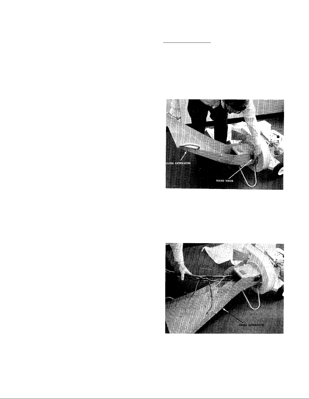
Feed the material so that it slides down the guide ex
tension. See figure 2.
OPERATION
Service engine with gas and oil. See engine man
ual packed with shredder for complete instruc
tions for the care and maintenance of engine.
READ DIRECTIONS CAREFULLY.
When ready to start engine, place throttle control
lever in START position and start engine in accord
ance with instructions in engine manual. After en
gine starts, move throttle control lever to desired
engine speed. The engine is stopped by placing
control lever in the STOP position.
CAUTION:
The manufacturer recommends that the operator ^
' wear safety glasses or some other suitable eye protec- .
tion as it is possible for chips to be ejected out of the
I inlet openings while feeding material.
FIGURE 2. FEEDING MATERIAL INTO GUIDE
Page 3

EXTENSION
A steady flow of material provides the best results.
Bulky material, such as stalks or heavy branches, should
be fed into the upper guide extension. See figure 3.
When sharpening blade, follow the original angle of
grind as a guide. It is extremely important that each
cutting edge receives an equal amount of grinding to
prevent an unbalanced blade. An unbalanced blade
will cause excessive vibration when rotating at high
speeds and may cause damage to the unit. Upon reas
sembly, make certain all parts are assembled properly
and tightened securely.
UrPER nUIDL I «IFNSI JN
ELASTIC LOCK NUT
FIGURE 3. FEEDING MATERIAL INTO UPPER GUIDE
EXTENSION
It is possible to feed too fast and you will find it will
take some experimenting with feeding rates to get
the most out of your shredder without stalling the en
gine.
Under certain conditions, it may be necessary to push
the materials into the inlet guide assembly. When this
becomes necessary, use a small diameter stick—NOT
YOUR HANDS. The stick should be of a size that will be
ground up if it gets into the impeller assembly.
The discharge chute will direct the shredded material
into a pile or a container. NOTE: Your shredder is
equipped with a nylon bag with drawstring lock. This
will accommodate a perforated disposable plastic bag.
CAUTION: Keep clear of the chute area since the
shredded material comes out with considerable velo
city. Always stop engine and disconnect spark plug
wire when changing bags.
LUBRICATION
WHEELS—Wheel bearings are of lifetime Fortiflex. They
require no lubrication.
ENGINE—Follow engine manual for lubrication instruc
tions.
CAUTION
Do Not deposit material larger
than Vi" diameter in hopper.
This may cause damage to the
shredding mechanism.
BEFORE STARTING
NOTE
Do not mix oil with gasoline.
1. Fill fuel tank with fresh regular gasoline. (See fig
ure 4.)
2. Fill crankcase with oil. (See figure 4.)
Fill with regular gasoline
Shorting Clip
Oil Dip Stick
MAINTENANCE
CAUTION: Always stop engine and disconnect spark
plug wire before doing any maintenance.
Cutting Blade—The blade may easily be removed for
grinding or replacement as follows:
1. Remove guide extension assembly by removing
four elastic locknuts. See figure 3.
2. Remove bolt (Ref. No. 54), lockwasher (Ref. No.
55) and flat washer (Ref. No. 20) holding blade
(Ref No. 56) to engine crankshaft. See figure 4.
3. NOTE: Blade is reversible and can be assembled
to crankshaft with either side showing.
Drain Plug
Oil Filler Plug
Drain Plug
FIGURE 4.
Page 4

PosiHon equipment so that engine is setting level.
Remove dip stick or oil filler plug (Figure 1). Pour
oil into oil filler tube from which dip stick was re
moved and fill to FULL mark on dip stick. Do not over
fill. After initial filling follow instructions on dip stick.
Be sure dip stick is screwed into filler opening as far
as it will go when measuring oil level.
During initial break-in period, oil level should be
watched closely See ENGINE MAINTENANCE.
Use MS classification oil. Do not use oils marked only
MM or ML or unmarked.
Above 32° use SAE 30; below 32° use SAE lOW These
recommendations must be followed for best perform
ance and long life.
Change oil first two (2) hours of operation and check
oil level every five (5) operating hours or each time
equipment is used.
Change oil every twenty-five (25) operating hours or
sooner if equipment is operated in extremely dusty or
dirty conditions.
TO STOP ENGINE
1. Press shorting clip against end of spark plug (fig
ure 4) and hold until engine stops running. If short
ing clip is not present move carburetor control to
STOP position, if key starting is used, turn key to
OFF position.
2. Turn off gasoline shutoff valve at underside of tank,
if engine is so equipped. Some engines may have
two valves, one at each end of tank.
3. Remove high tension wire from spark plug to pre
vent accidental slating by children while equip
ment is unattended.
ENGINE MAINTENANCE
To obtain long life and trouble-free service from
your engine, certain normal maintenance must be per
formed as outlined below:
NOTE: Carburetors are preset at the factory. DO NOT
attempt to make adjustments at this time. See carbu
retor instructions outlined under CARBURETOR AD
JUSTMENT.
NOTE: If engine is equipped wth 6:1 gear reduction
use the following recommended oil weights in the
gear box.
Above 32°F use EP 90 in gear box; below 32°F use
SAE low in gear box.
TO START ENGINE
CAUTION
If engine is used on lawnmower, be
sure to keep clear of mower blade at
all times.
1. Be sure shorting clip (figure 4) is away from spark
plug if engine is so equipped.
2. Be sure that fuel valve, if present, under fuel tank
is turned on or opened and that the spark plug
wire is properly attached.
1. Change oil in crankcase after first two (2) hours of
operation. Then, follow instructions outlined at left.
CAUTION
Disconnect high tension wire at spark
plug to prevent accidental starting of
engine. Unscrew oil drain plug located
on side at bottom of engine (figure 4).
NOTE: Always tip engine toward oil drain hole. Be
sure oil drains completely.
Replace oil drain plug and refill with oil as directed
on page 5 or engine nameplate.
2. Check oil every five (5) operating hours or each
time equipment is used.
If engine has dip stick, keep oil level at mark indicated
by adding if necessary.
3. Cleaning engine—This is an aircooled engine which
operates most efficiently when the cooling fins ace
clean.
Clean cylinder fins and underside of tanjc or housing
thoroughly of all accumulated grass and debris.
3. If equipment is equipped with remote engine and
speed controls, set control in CHOKE or START po
sition.
Some equipment may have the controls on the engine.
Set control on CHOKE or START.
4. Rewind starters—Use quick full arm stroke. Keep
firm grip on handle and return rope slowly.
Be sure equipment controls are in NEUTRAL and that
engine controls are set for starting. Stand clear of
mower and move release lever to START position.
After engine has started, move carburetor control off
CHOKE or STARTING position and on to RUN position.
4. Air Cleaners
a. Paper Type Element. Remove every 10 hours or
oftener if under dusty conditions. Tap to remove
loose dirt and/or blow from inside out with low
pressure air. Replace if torn or perforated or when
plugged to maintain proper carburetor setting (50
hours). DO NOT WASH IN ANY LIQUID AND DO
NOT OIL.
b. Oil Bath. Remove element. Clean element and bowl.
Using same oil used for engine, fill bowl to line.
Replace element.
CAUTION: Do not pour oil down center of bowl (fig
ure 6).
Page 5

FIGURE 5.
‘Attaching Screw
Paper Element
Element
4. Open one and one-half 1 Vi turns (counter-clock
wise).
5. Start engine. Follow starting instructions page 5.
6.
With throttle open (carburetor control at RUN or
FAST position) adjust power adjusting needle oneeighth (Vs) turn at a time forward or backward un
til engine runs smoothly. If engine tends to stall
under load enrich mixture slightly (counterclock
wise).
7. Hold throttle lever closed or move carburetor con
trol to IDLE or SLOW position and adjust idle ad
justing needle until engine runs smoothly proceed
ing as in step six (6) above.
8. Allow several seconds between each adjustment
when performing either step six (6) or seven (7) to
allow engine to react to new setting.
FIGURE 6
CARBURETOR ADJUSTMENTS
Do not make unnecessary adjustments. Factory settings
are correct for most application. If adjustments are
needed, proceed as follows:
1. Close power adjusting needle (figure 7) by turning
to right (clockwise). Close finger tight only. Forcing
will cause damage.
2. Open one turn (counterclockwise).
3. Close idle adjusting needle (figure 7) by turning to
right (clockwise). Qose finger tight only. Forcing
will cause damage.
FIGURE 7.
STORAGE INSTRUCTIONS
In event engine is to be stored for any length of time
(30 days or more) or at the end of mowing season,
prepare as follows:
1. Drain gasoline by tipping or by syphon hose, then
run engine until remainder is used and tank and
carburetor are empty.
CAUTiON: Drain into container outdoors away from
fire or flame.
2. Drain carburetor by pressing upward on bowl
drain (figure 7).
3. Inside protection of engine for storage is performed
by removing spark plug and pouring one ounce of
SAE 30 oil through spark plug hole into cylinder.
Crank engine, without starting, several times to
spread oil over cylinder walls.
Page 6

• ■ „ . '.r t.l t lU US »BOU T THIS ART ICL E OR
■ F Y OU 3ROER REP LAC EME NT PAR TS ALW AYS
N'fNI iON T HIS STO CK AND MO DEL NU MBE R
£
to
keep this door
closed except
when feeding
material
Page 7

PARTS LIST FOR MODEL 243-650 POWER SHREDDER
REF.
PART COLOR
NO. CODE
NO.
1
2 11464—463
3 712-123
4
736-119
5
712-123
6
736-119
7
726-221
8
7006
9
10
736-100
11
114751—463
12
710-237
13 712-429
14
710-237
15
714-115
16
711-564
17
18
736-192
19
711-578
20
736-247
1 21
22
23
24
712-429
25
26
27
28
29
30
9966
736-264
11480
712-429
736-264
711-566
31 712-107
32
710-289
33
11460 —463
34
35
712-429
8306 —522
11459—463
11474—463
11454 —463
11467 —463
11472—463
DESCRIPTION
Engine
Engine Mounting Plate
Hex Nut 5/16-24 Thd.*
Spring Lockwasher 5/16" Scr.*
Hex Nut 5/16-24 Thd.*
Spring Lockwasher 5/16" Scr.*
Push Cap
Fortiflex Bearing
Wheel Ass'y. Complete
Flat Washer '/2" I.D. ^
Axle
Hex Hd. Cap Scr. 5/16-24 x
%"Lg.*
Elastic Stop Nut 5/16-18 Thd.
Hex Hd. Cap Scr. 5/16-24 x
%" Lg.*
Cotter Pin 14" Dia. x 1" Lg.
Flail Spacer 23/32" Lg.
Flail a.SS“
Flat Washer 17/32 I.D. x 15/16
O.D. X .09 Thk.
Clevis Pin Vi" Dia. x 3" Lg.
Flat Washer .406 I.D. x
VA"
O.D.(Hardened)
Flail Housing Ass'y.—Comp.
Back-up Plate
Inlet Guide Ass'y.
Elastic Stop Nut 5/16-18 Thd;
Knob Ass'y.
Flat Washers
V2"
Dia.
Stop Washer
Elastic Stop Nut 5/16-18 Thd.
Flat Washer—5/16" Scr.*
Chute Pivot Rod
Lock Nut Vi-20 Thd.
Hex Hd. Cap Scr. Vi-20 x
’/2" Lg.*
Guide Extension Ass'y.
Guide Extension
Elastic Stop Nut 5/16-18 Thd.
NEW
PART
N
REF.
NO.
36
PART COLOR
NO. CODE
11479—463
37 710-289
712-107
38
39 11477—463
726-111
40
41 11478
42 712-109
43 11476—463
44
710-465
45 711-580
46
47
48
11481 —463
736-921
726-111
49 711-579
50
11455—463
51 712-922
52
710-621
53 714-507
54 710-331
736-217
55
56
57
58
59
11458 —463 Blade
714-114
11473 —463
710-237
60 736-119
61
11452 —463
63 712-107
64
11465—463-
65
764-12i5
66
736-119
DESCRIPTION
Clamp Rod Ass'y.
Hex Hd. Cap Scr. ’A-20 x ’/
2
"
Lg.*
Lock Nut Vi-20 Thd.
Upper Guide Extension Assy.
Palnut 3/16" Dia.
Hinge Pin
Wing Nut Elastic Vi-20 Thd.
Door—Upper Guide Extension
Hex Hd. Cap Scr. /2-20 x
4V2" Lg.
Clevis Pin
Hopper Ass'y.
Lockwasher ’/2" Screw
Palnut 3/16" Dia.
Flail Spacer 7/32" Lg.
Cutting Finger
Hex Jam Nut ’/2-20 Thd.
Hex Hd. Cap Scr. 5/16-18
X
’/2" Lg.*
Cotter Pin 3/32" Dia. x Lg.
Hex Hd. Cap Scr. %-24 x
2’A" Lg. Heat Treated
Spring Lockwasher %"
Heavy Duty
7,h4"
Square Key
Va"
x
Va"
x 2" Lg
Impeller Ass'y.
Hex Hd. Cap Scr. 5/16-24 x
%" Lg.*
Spring Lockwasher 5/16"
Scr*
Hopper to Engine Mtg. Plate
Locknut ’/
4-20
Thd.
Chute Deflector -)
Nylon
BAG
w/CVf/9^y String
and Lock
Spring liockwasher 5/16"
Scr.*
NEW
PART
*For fatter service obtain standard nuts and bolts locally- 1^ these items
cannot be obtained locally, order by part number and size as shown
on the parts list.
NOTE: This instruction manual covers various models and all accessories shown do not
necessarily apply to your model mower.
The engine is not under warranty by the mower manufacturer. If repairs or service is needed on
the engine, please contact your nearest authorized engine service outlet. Check the "Yellow
Pages" of your telephone book under "Engines — Gasoline."
(463—Top Flite Red)
When ordering parts, if color or finish is important use the appropriate
color code shown above (e.g. Top Flite Red—11464 (463).)
Page 8

PARTS INFORMATION
DEFECTIVE OR MISSING PARTS must be reported to the
factory iiTimediately. Such claims must include your
model number and date of purchase.
MOWER, TILLER, SNOW THROWER, TRACTOR, TRAIL
BIKE AND MUD BUG PARTS
Mower, tiller, snow thrower, tractor, trail bike and
mud bug parts are available through the authorized
service firms listed below. All orders should specify
the model number of your unit, parts numbers, de
A 1 Engine & Mower Co.
327 East 9th Street
Salt Lake City, Utah 84102
American Electric Ignition Co.
124 H.yj. 8th Street
Oklahoma City, Oklahoma 73102
Auto Electric & Carburetor Co.
2625 4th Avenue, S.
P. O. Box 1948
Birmingham, Alabama 35233
Automotive Equipment Service Co.
3117 Holmes Street
Kansas City, Missouri 64109
Bailey's Rebuild Inc.
1325 E. Madison Street
Seattle, Washington 98102
Brown Equipment Distributor Inc.
110 Beech Street
Corydon, Indiana 47112
Bullard Supply
2409 Commerce Street
Houston, Texas 77003
Catto & Putty, Inc.
P. O. Box 2408
510 Soledad Street
San Antonio, Texas 78205
Center Supply Company
6867 New Hampshire Avenue
Takoma Park, Maryland 20012
Charles B. Wright Co.
309 4th Avenue, South
Nashville, Tennessee 37201
W. B. Clements
400 Salem Avenue
Roanoke, Virginia 24016
Morton B. Collins Co.
300 Birnie Avenue
Springfield, Massachusetts 01107
Dixie Sales Company
P. O. Box 1408
327 Battleground Avenue
Greensboro, North Carolina 27402
East Point Cycle & Key Shop
1617 White way
East Point, Georgia 30044
Gamble Distributors
West End Avenue
Carthage, New York 13619
Garden Equipment Co., Inc.
6600 Cherry Avenue
Long Beach, California 90805
Henzier, Inc.
2015 Lemay Ferry Road
St. Louis, Missouri 63125
Frank E. Ives & Son
1101 Lincoln Avenue
Prospect Park, Pennsylvania 19076
J. W. Jewett Co.
981 Folsom Street
San Francisco, California 94107
Kenton Supply
8216 North Denver Avenue
Portland, Oregon 97217
Kimber's Inc.
115 W. Geddes St.
Syracuse, New York 13204
The Lawnmower Shop
1340 El Camino Real
San Carlos, California 94070
Marr Brothers
423 E. Jefferson
Dallas, Texas 75203
Mathews Auto Electric Co.
420 East 2nd Street
Tulsa Oklahoma 74120
McClure Lawn & Garden Supply
1114 Lexington Avenue
Mansfield, Ohio 44907
Memphis Cycle & Supply Co.
421 Monroe Avenue
Memphis Tennessee 38103
scription of parts and the quantity of each part re
quired.
BRIGGS & STRATTON, TECUMSEH AND PEERLESS PARTS
AND SERVICE
Briggs & Stratton, Tecumseh and Peerless parts and
service should be handled by your nearest authorized
engine service firm. Check the yellow pages of your
telephone directory under the listing Engines —
Stratton or Tecumseh Lauson —
Gasoline, Briggs
Power Products.
&
Moz-AII of Florida, Inc.
365 Greco Avenue
Coral Gables, Florida 33146
National Central, Div. of
Joe Sterling, Inc.
Drawer "D" 687 Seville Rd.
Wadsworth, Ohio 44281
Power Equipment Distributor
36463 So. Gratiot Avenue
Mt. Clemons, Michigan 48043
Parts & Sales Inc.
2101 Industrial Pkwy.
Elkhart, Indiana 46514
Parts & Sales Inc.
335 West St. Charles Road
Villa Park, Illinois 60181
Power Lawn & Garden Equip. Co.
2551-2571 J. F. Kennedy Road
Dubuque, Iowa 52001
Raub Supply Company
James & Mulberry Sts.
Lancaster, Pennsylvania 17604
Radco Distributors
2403 Market Street
P. O. Box 3216
Jacksonville, Florida 32206
Richmond Battery & Ignition
P. O. Box 25369 - 957 Myers St.
Richmond, Virginia 23260
Smith Hardware Company
515 N. George Street
Goldsboro, North Carolina 27530
South Denver Lawn Equip. Co.
527 West Evans
Denver, Colorado 80223
Suhren Engine
8330 Earhart Blvd.
New Orleans, Louisiana 70118
Sutton's LaWn Mower Shop
Route 4, Box 343
North Little Rock, Arkansas 72117
Warner Equipment
7520 Lyndale Avenue, So.
Minneapolis, Minnesota 55423
WARRANTY PARTS AND SERVICE POLICY
The purpose of warranty is to protect the customer from defects in material and workmanship, defects
which are not detected at the time of manufacture.
Our aim is to build into our product quality and reliability. Considerable emphasis is placed on quality
control in order to assure our customer of satisfactory product performance. To achieve this goal, it is
necessary to gain the cooperation of all concerned, MTD, our sales force and our customers.
MTD's responsibility is to build a quality product and to back up that product. MTD must build this
quality product at a competitive price. This cannot be achieved without production in quantity. Quantity
production is mass production. In mass production it is always possible for undetected defects to be
present when the product reaches the customer. Our warranty is extended to assure the customer that
any such defects will be corrected.
Use and maintenance are the responsibility of the customer. MTD cannot assume responsibility for con
ditions over which it has no control. MTD's responsibility does not cover misuse, excessive use, accident
neglect, improper maintenance or alterations by unauthorized persons. Satisfactory product performance
can only result when a manufacturer provides and backs up a quality product and the customer follows
through with proper use and proper maintenance of that product. When both the manufacturer and the
customer recognizes and assumes his responsibility, satisfactory product performance and customer sat-
isfactjon ere assured.
FORM NO. 770-4713
8 **
PRINTED IN U.&.A
 Loading...