

Page 1

lOct
Model No.
EDGER
243-600
IMPORTANT
SAFE OPERATION PRACTICES - WALK BEHIND EDGER
TRAINING
1. Read the Operating and Service Instruction Manual
carefully. Be thoroughly familiar with the controls and
proper use of the equipment.
2. Never allow children to operate a power edger.
3. Keep the area of operation clear of all persons, partic
ularly small children, and pets.
PREPARATION
1. Thoroughly inspect the area where the equipment is
to be used and remove all stones, sticks, wire, bones
and other foreign objects.
2. Do not operate equipment when barefoot or wearing
open sandals. Always wear substantial footwear.
3. Check fuel before starting engine. Do not fill gasoline
tank indoors, when engine is running, or while engine
is still hot. Wipe off any spilled gasoline before start
ing engine.
4. Never attempt to make a wheel height adjustment while
engine (motor) is running.
5. Edge only in daylight or in good artificial light.
6. Never operate equipment in wet grass. Always be sure
of your footing; keep a firm hold on the handle and
walk, never run.
5. If the equipment should start to vibrate abnormally, stop
the engine (motor) and check immediately for the
cause. Vibration is generally a warning of trouble.
6. Stop engine (motor) whenever you leave the equipment,
before cleaning housing, and when making any repairs
or inspections.
7. When cleaning, repairing or inspecting, make certain
blade and all moving parts have stopped. Disconnect
spark plug wire and keep wire away from plug to pre
vent accidental starting.
8. Do not run engine (motor) indoors.
9. Never operate edger without proper guards, plates or
other safety protective devices in place.
OPERATION
1. Do not change engine governor settings or overspeed
engine.
2. Do not put hands or feet near or under rotating parts.
Keep clear of discharge opening at all times.
3. Stop blade when crossing gravel drive, walks or roads.
4. After striking a foreign object, stop the engine (motor),
remove wire from spark plug, thoroughly inspect the
edger for any damage, and repair the damage before
restarting and operating the edger.
MTD PRODUCTS INC
5389 WEST 130th STREET
MAINTENANCE AND STORAGE
1. Check blade and engine mounting bolts at frequent
intervals for proper tightness.
2. Keep all nuts, bolts, and screws tight to be sure equip
ment is in safe working condition.
3. Never store equipment with gasoline in the tank inside
of a building where fumes may reach an open flame or
spark. Allow engine to cool before storing in any en
closure.
4. To reduce fire hazard keep engine free of grass, leaves
or excessive grease.
P.O. BOX 2741 CLEVELAND OHIO 44111
FORM NO. 770-4139
Page 2
®Oo
Page 3

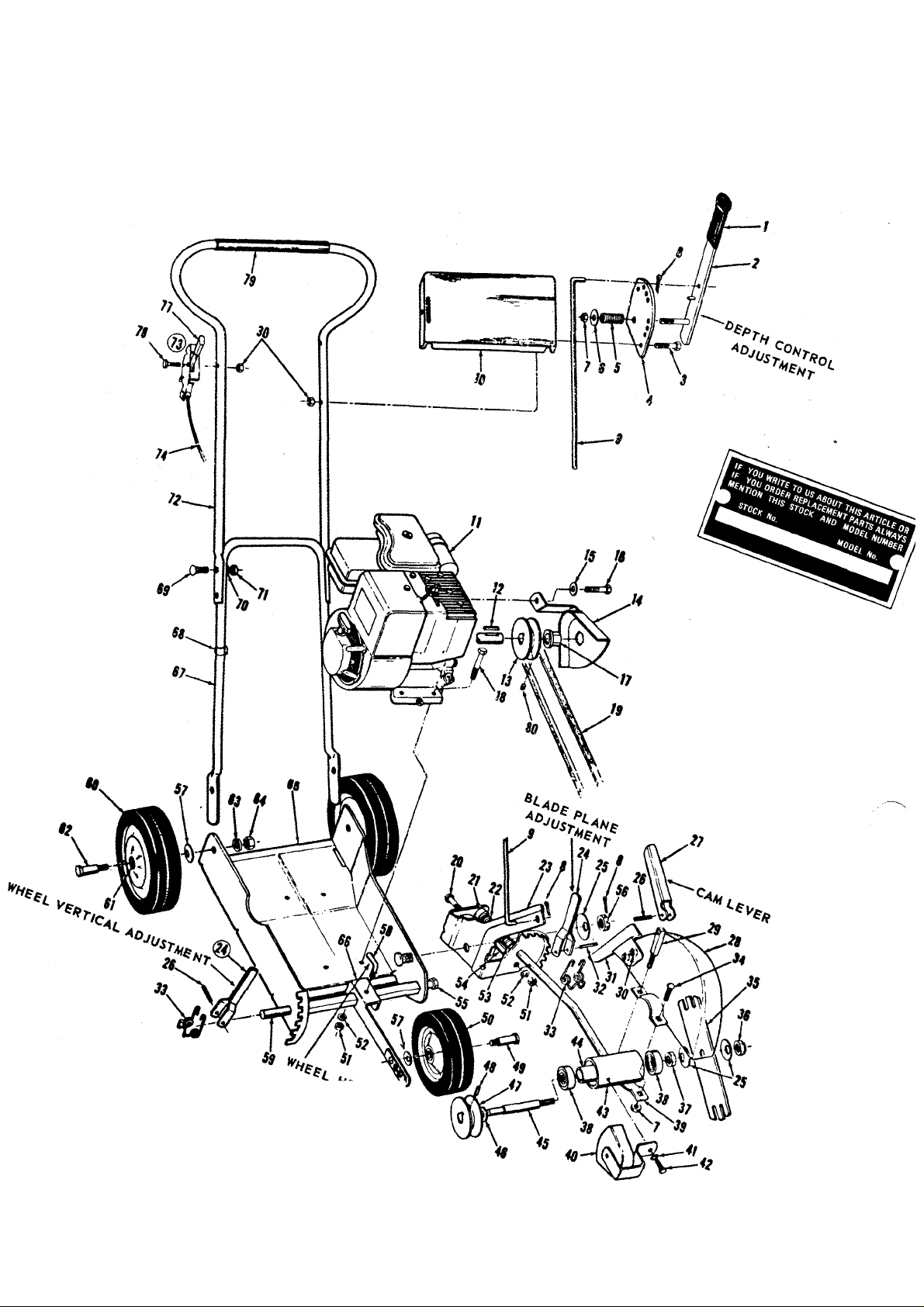
PARTS LIST FOR 243-600 EDGER
Ref.
Part
No.
No.
1 720-142
2
9948
3 710-106
Color
Code
Description
Flat Bar Grip
Clutch Handle Assembly
Hex Head Cap Screw
K-20x1>i Lg. *
New
Part
Part
Ref.
No.
39
40
736-329
41
710-179 Hex Head Thread Cut Screw
42
No.
Color
Code
Description
10244 Clamp Bracket
9944-463 Belt Guard Assembly
Spring Lockwasher % Screw *
4 9950 Clutch Plate type“F”)4-20xJ/2Lg. *
5 732-171
736-264
6
Compression Spring
Flat Washer *
7 712-372 Hex Centerlock Nut 18 Thd. *
8 714-474 Cotter Pin Vt Dia. *
9 9951 Clutch Rod
10 10113-463
11
12
714-105 Square Key .187 sq. x 1 ” Lg. *
Handle Cover
Engine
13 711-421 Pulley—Engine
14 9941-463 Belt Guard Assembly
15 736-114 Internal Lockwasher Dia. *
16 710-121 Hex Head Cap Screw
^2-20 X Lg.
17 748-227 Hex Bearing
710-442 Hex Head Cap Screw
18
Ji6-18xiy2" Lg.
19
754-142
V-Belt%"x31.2Lg. *
20 710-402 Hex Head Cap Screw
?i6-18x4y2"Lg.
21
711-379
22
732-187 Compression Spring 63
23 9932
24
9946
Bushing
Pivot Bracket Assembly
Lever Assembly 65 9930-463 Base Assembly
25 736-112 Belleville Washer *
26
715-119
27
9953
28 9938-463
29
711-383
30 712-107
31
9952 Guide
32
712-101
33
732-188
34
710-444 Hex Head Cap Screw
Roll Pin ^2" X 3/4" Lg.* 67 9955 Handle—Lower
Cam Lever
Guard Assembly
Stud
Hex Centerlock Nut K—20 Thd. * 71 712-287
Roll Pin %"x1K2"Lg.*
Tension—Spring
%-18x1"Lg. *
35 9954 Blade
36
37
38
712-200
712-922
741-124
Hex Elastic Stop Nut >2—20 Thd. *
Hex Jam Nut '4—20 Thd. * 80
Bearings #203
43
44
45
46
47
48
49
50
51
52
53
54
55
56
57
58
59
60
61
62
9934
711-385
711-384 Spindle
736-116 Flat Washer .625 I.D. x .937 O.D. *
711-420 Pulley-Spindle
715-246 Spirol Pin % Dia. xV/i" Lg. *
738-213
9392-513
712-267
736-119
715-111
711-386 Spacer
711-110
712-114
736-105
711-207
711-382
9392-514
7006 Fortiflex Bearing
738-108 Axle Bolt—Rear
736-169
712-798 Hex Nut%-16Thd. *
64
9936-463
66
746-145
68
69 710-111 Carriage Bolt A—20 x 154 Lg. *
736-329 Spring Lockwasher 54"Screw*
70
10112
72
10449
73
732-200
74
77 7470
78 710-606 Hex Head Cap Screw
79 718-124
710-137
Spindle Housing t
Spacer
Axle Bolt—Front Wheel
Wheel Assembly 7" Dia.—Front
Hex Nut %—18 Thd.
Spring Lockwasher Screw *
Spirol PinKa" Dia.x 1" Lg. *
Shoulder Bolt
Castle Hex Nut 'A-20 Thd. *
Belleville Washer *
Lock Handle
Shaft
Wheel Assembly 8" Dia.—Rear (2)
Spring Lockwasher for Vs" Screw *
Wheel Bracket Assembly
Cable Clip
Hex Nut 54-20 Thd. *
Handle—Upper
Throttle Control Complete
Conduit and Wire **
Knob **
54-20x 154 Lg. *
Grip —Handle
Set Screw %—24 Thd. *
New
Part
*For faster service order standard nuts, bolts, and washers locally. If these items cannot be obtained locally, order by
part number and size as shown on parts list.
463 — Top Flite Red — When ordering parts, if color or finish is important, use the appropriate color code shown at
left. (e.g. Top Flite Red 10112 (463))..
tTo order spindle housing complete with two bearings, spacer and spindle shaft order part number 10229.
^*Part of throttle control complete 10449.
The engine is not under warranty by the
edger manufacturer. If repairs or service is
needed on the engine, please contact your
nearest authorized engine service outlet.
Check the "Yellow Pages" of your
telephone book under "Engines —
Gasoline."
Find utfastinthn
Page 4

ASSEMBLY
Your new edger is shipped preassembled with the excep
tion of the handle, rear wheels, and throttle control.
1. Remove the edger and all parts from the carton. Make
certain that all loose parts and literature are removed
from carton before carton is discarded.
2. Assemble the lower handle into the slots in the rear of
the frame. Line up the holes in the handle with the holes
in the frame and insert the axle bolt through the wheel,
belleville washer, frame, handle, lockwasher and secure
with hex nut as shown on the parts drawing.
3. Assemble the upper handle assembly to the lower han
dle with four carriage bolts, lockwashers and nuts.
4. Assemble the clutch rod to the clutch handle and pivot
bracket assembly and secure with cotter pins.
5. Check the lubrication section of this manual for proper
engine lubrication care.
STARTING INSTRUCTIONS
1. Fill the crankcase with oil. See Lubrication section of
this manual.
2. Fill the gasoline tank with “regular” gasoline.
3. Move the depth control adjustment lever back as far
as it will travel and engage the pin in the clutch plate
(ref. no. 4).
4. Set the engine control in the “choke” position.
5. Grasp the starter handle and pull out the cord rapidly.
Return it slowly to the engine. If the engine does not
start after two pulls, move the engine control to the
“fast” position.
CONTROLS
ENGINE — One lever operates the choke, regulates the
engine speed and stops the engine. Ref. No. 73.
DEPTH CONTROL ADJUSTMENT - The clutching and
declutching of the belt is accomplished by moving the
clutch handle. To declutch pull the handle towards you
as you operate the edger. The farther you push the handle
forward the deeper the cut. To operate the clutch handle,
move it to the left so the pin clears the clutch plate. Ref.
No. 4.
CAM LEVER — The cam lever releases the blade guard
assembly so it can be rotated to any position. The cam
lever can be tightened by adjusting the hex nut on the
stud (ref. no. 29). Ref. No. 27.
BLADE PLANE ADJUSTMENT - The cutting blade can be
adjusted from vertical to horizontal position by releasing
the lever on the pivot bracket assembly and rotating the
spindle housing. The notches will hold it in any position.
Ref. No. 24.
WHEEL HORIZONTAL ADJUSTMENT - Loosening the
lever on the front of the frame will allow you to move the
front wheel bracket assembly to either side of the frame.
Ref. No. 58.
WHEEL VERTICAL ADJUSTMENT - By releasing the
lever on the R. H. side of the frame you can raise and lower
the front wheel of your edger. Additional adjustment can
be made by unscrewing the axle bolt and using the differ
ent holes in the end of the wheel bracket assembly. Ref.
No. 24.
By becoming familiar with all the controls and adjust
ments before you operate your edger you will be able to
easily adjust your edger to a variety of cutting and trim
ming conditions. While the engine is running, DO NOT
ATTEMPT TO MAKE ANY ADJUSTMENTS except with
the engine control or the depth control adjustment.
LUBRICATION
ENGINE — Fill sump with oil. Use a high quality detergent
oil classified “For Service MS”. Nothing should be added
to the recommended oil. SUMMER—Use SAE 30. WINTER-(Below 40° F.) Use SAE 5W-20 or SAE 10W.
Dire c tio ns : Place the engine level. Remove filler plug.
FILL THE OIL SUMP TO POINT OF OVER
FLOW. Pour slowly.
WHEELS — The wheel bearings are lifetime fortiflex and
require no lubrication.
CUTTER HEAD BEARINGS - The two ball bearings in the
cutter head are lubricated and sealed at the factory and
require no lubrication. Lubricate all other moving parts
with engine oil.
MAINTENANCE
BLADE REMOVAL — Use a wrench on both sides of the
blade when removing it for replacement.
BELT REMOVAL — To remove the V-Belt, remove the belt
guard on the engine pulley and the belt guard on the
spindle housing. Replace with a % x 31.2" V-Belt. (Part
Number 754-142.)
Page 5

OPERATING INSTRUCTIONS
1. Loosen the lever (ref. no. 58) on the wheel horizontal
adjustment and move it all the way to the right and tighten
the lever.
5. Guard ass'y. (ref. no. 28) is adjustable horizontally. If
operator is on walk as in fig. 2, pull guard ass'y. (ref. no. 28)
to the right so that the inside of guide (ref. no. 32) is to the
walk. If operator is on lawn, pull the guard ass'y. (ref. no.
28) to the left. This allows the outside of guide
2. Move the depth control adjustment lever down until the
blade engages in the ground.
3. Be sure the guide (ref. no. 31) which is mounted on the
guard ass'y. (ref. no. 28) follows in the fresh cut of the
blade. (See position of guard, fig. 1).
4. Be sure guide (ref. no. 31) rides against the walk (see fig. 2)
below.
FRONT WHEEL
(REF. NO. 50)
-GUARD ASS'Y
(REF. NO. 28)
(REF. NO. 35)
(ref. No. 31) to be towards the walk. This will protect your
blade from wear and damage.
6. To operate the edger as a trimmer, rotate the cutter head
90° by adjusting the blade plane adjuster.
7. The edger can be adjusted by lowering the front wheel with
the wheel vertical adjustment so the front wheel will roll in
the street while the rear wheel is on top of the curb.
FLAT DRIVE
CAUTION
Do not adjust the blade guard with the engine running.
Page 6

PARTS INFORMATION
DEFECTIVE OR MISSING PARTS must be reported to the
factory immediately. Such claims must include your
model number and date of purchase.
MOWER, TILLER, SNOW THROWER, TRACTOR,
TRAIL BIKE, MUD BUG AND EDGER PARTS
Mower, tiller, snow thrower, tractor, trail bike, mud bug
and edger parts are available through the authorized service
firms listed below. All orders should specify the model
number of your unit, parts numbers, description of parts
and the quantity of each part required.
A 1 Engine & Mower Co.
327 East 9th Street
Salt Lake City, Utah 84102
American Electric Ignition Co.
124 N. W. 8th Street
Oklahoma City, Oklahoma 73102
Auto Electric & Carburetor Co.
2625 4th Avenue, S.
P. O. Box 1948
Birmingham, Alabama 35233
Automotive Equipment Service Co.
3117 Holmes Street
Kansas City, Missouri 64109
Bailey's Rebuild Inc.
1325 E. Madison Street
Seattle, Washington 98102
Brown Equipment Distributor Inc.
110 Beech Street
Corydon, Indiana 47112
Bullard Supply
2409 Commerce Street
Houston, Texas 77003
Catto & Putty, Inc.
P. O. Box 2408
510 Soledad Street
San Antonio, Texas 78205
Center Supply Company
6867 New Hampshire Avenue
Takoma Park, Maryland 20012
Charles B. Wright Co.
309 4th Avenue, South
Nashville, Tennessee 37201
R. T. Clapp Co.
2016 Magnolia Ave., N. E.
Knoxville Tennessee 37917
W. B. Clements
400 Salem Avenue
Roanoke, Virginia 24016
Morton B. Collins Co.
300 Birnie Avenue
Springfield, Massachusetts 01107
Dixie Sales Company
P. O. Box 1408
327 Battleground Avenue
Greensboro, North Carolina 27402
East Point Cycle & Key Shop
1617 Whiteway
East Point, Georgia 30044
Gamble Distributors
West End Avenue
Carthage, New York 13619
Garden Equipment Co., Inc.
6600 Cherry Avenue
Long Beach, California 90805
Henzier, Inc.
2015 Lemay Ferry Road
St. Louis, Missouri 63125
Frank E. Ives & Son
1101 Lincoln Avenue
Prospect Park, Pennsylvania 19076
J. W. Jewett Co.
981 Folsom Street
San Francisco, California 94107
Kenton Supply
8216 North Denver Avenue
Portland, Oregon 97217
Kimber's Inc.
115 W. Geddes St.
Syracuse, New York 13204
The Uwnmower Shop
1340 El Camino Real
San Carlos, California 94070
Marr Brothers
423 E. Jefferson
Dallas, Texas 75203
Mathews Auto Electric Co.
420 East 2nd Street
Tulsa Oklahoma 74120
McClure Lawn & Garden Supply
1114 Lexington Avenue
Mansfield, Ohio 44907
Memphis Cycle & Supply Co.
421 Monroe Avenue
Memphis Tennessee 38103
scription of parts and the quantity of each part re
quired.
BRIGGS & STRATTON, TECUMSEH AND PEERLESS PARTS
AND SERVICE
Briggs & Stratton, Tecumseh and Peerless parts and
service should be handled by your nearest authorized
engine service firm. Check the yellow pages of your
telephone directory under the listing Engines —
Gasoline, Briggs & Stratton or Tecumseh Lauson —
Power Products.
rower rrouutis. Moz-AII of Florida, Inc.
365 Greco Avenue
Coral Gables, Florida 33146
National Central, Div. of
Joe Sterling, Inc.
Drawer "D" 687 Seville Rd.
Wadsworth, Ohio 44281
Power Equipment Distributor
36463 So. Gratiot Avenue
Mt. Clemons, Michigan 48043
Parts & Sales Inc.
2101 Industrial Pkwy.
Elkhart, Indiana 46514
Parts & Sales Inc.
335 West St. Charles Road
Villa Park, Illinois 60181
Power Lawn & Garden Equip. Co.
2551-2571 J. F. Kennedy Road
Dubuque, Iowa 52001
Raub Supply Company
James & Mulberry Sts.
Lancaster, Pennsylvania 17604
Radco Distributors
2403 Market Street
P. O. Box 3216
Jacksonville, Florida 32206
Richmond Battery & Ignition
P. O. Box 25369 - 957 Myers St.
Richmond, Virginia 23260
Smith Hardware Company
515 N. George Street
Goldsboro, North Carolina 27530
South Denver Lawn Equip. Co.
527 West Evans
Denver, Colorado 80223
Suhren Engine
8330 Earhart Blvd.
New Orleans, Louisiana 70118
Sutton's LaWn Mower Shop
Route 4, Box 343
North Little Rock, Arkansas 72117
Warner Equipment
7520 Lyndale Avenue, So.
Minneapolis, Minnesota 55423
For one year from date of purchase, MTD Products Inc will replace for the original purchaser,
free of charge, F. O. B. factory or authorized service firm, any part or parts found to be defective
in material or workmanship. Ail transportation charges on parts submitted for repiacement under
this warranty must be paid by the purchaser. This warranty does not include replacement of parts
which become inoperative through misuse, excessive use, accident, neglect, improper mainte
nance or alterations by unauthorized persons. This warranty does not include the engine, motor,
battery, battery charger or any component parts thereof. For service on these units, refer to the
applicable manufacturer’s warranty.
The above warranty will apply only to the original owner and will be effective only if the war
ranty card has been properly processed. It will not apply where the unit has been used commer
cially.
Warranty service is available through your local authorized service dealer or distributor.
UNDER NO CIRCUMSTANCES WILL THE RETURN OF A COMPLETE UNIT BE ACCEPTED BY
THE FACTORY UNLESS PRIOR WRITTEN PERMISSION HAS BEEN EXTENDED.
FORM NO. 770-4139
WARRANTY
PRINTED IN U.S.A.
 Loading...