

MTD 242A645-000 User Manual
OWNEirS GUIDE
• ASSEMBLY • OPERATION • MAINTENANCE • PARTS •
5 and 8 H.P.
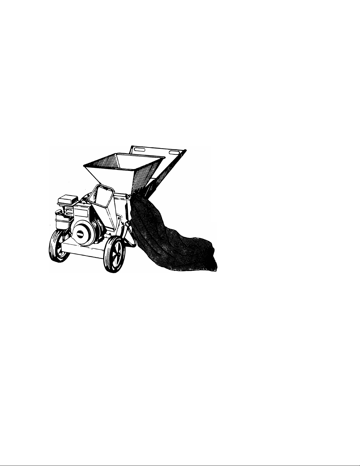
SHREDDERS
$1.00
Important:
Read Safety Rules
and Instructions Carefully
Model Numbers
242-645-000
242-648-000 /
rs MULiJ
242A645-000
242A648-000j
IMPORTANT!
Record the Model No. and Mfg. Code which
appear on your unit in the space below. You
must have these numbers, along with the date
of purchase, in order to receive warranty or ser
vice.
MEETS ANSI SAFETY STANDARDS
MODEL NO. MFG. CODE
’XMPELLEP^
/Iss/
AMERICA
WARNING: This unit is equipped with an internal combustion engine and should not be used
on or near any unimproved forest-covered, brush-covered or grass-covered land unless the
engine’s exhaust system is equipped with a spark arrester meeting applicable local or state
laws (if any). If a spark arrester is used, it should be maintained in effective working order by
the operator.
In the State of California the above is required by law (Section 4442 of the California Public
Resources Code). Other states may have similar laws. Federal laws apply on federal lands.
A spark arrester for the muffler is available through your nearest engine authorized service
dealer or contact the service department, P.O. Box 360900, Cleveland, Ohio 44136.
FORM NO. 770-7048G

A
SAFETY RULES
WARNING: TO REDUCE THE POTENTIAL FOR ANY INJURY, COMPLY WITH THE FOLLOWING
SAFETY INSTRUCTIONS. FAILUF E TO COMPLY WITH THE INSTRUCTIONS MAY RESULT IN
PERSONAL INJURY.
TRAINING
• Read this owner’s manual carefully in its entirel/ before
attempting to assemble or operate this machine. Be com
pletely familiar with the controls and the proper use of
this machine before operating it. Keep this manual in a
safe place for future and regular reference and f )r order
ing replacement parts.
• Children must never be allowed to operate this equip
ment.
• No one should operate this unit while intoxicated or while
taking medication that impairs the senses or reac Jons.
• This equipment should never be operated in th(i vicinity
of children, pets or other persons.
• Never run your machine in an enclosed area as the
exhaust from the engine contains carbon monoxic e, which
is an odorless, tasteless and deadly poisonous ga 3.
• Never place your hands or any part of your body or cloth
ing inside the feeding chamber, discharge chute or near
any moving part while the machine or engine is running.
• If it is necessary for any reason to inspect or rapair the
feeding chamber or any part of the machine wher 5 a mov
ing part can come in contact with your body or clothing,
stop the machine, allow it to cool, disconnect the spark
plug wire from the spark plug and move it away from the
spark plug before attempting such inspection or re pair.
PREPARATION
• Wear safety glasses provided with your unit whilu operat
ing the shredder to prevent injury from any mater al which
may be ejected out of the openings.
• Wear proper apparel. Avoid wearing loose fitting clothing.
Wear gloves when handling material.
• HANDLE GASOLINE WITH CARE as it is an e<tremely
flammable fuel.
• Check the fuel before starting the engine. Do not fill the
fuel tank indoors, while the engine is running, or while the
engine is still hot. Turn the unit off and let the enqine cool
before refueling.
• Fuel your shredder in a clean area. Do not smoke while
refueling.
• Fuel tank cap must be secure at all times except during
refueling.
• Avoid spilling gasoline or oil. Wipe the unit clean )f any
spilled fuel or oil.
• Store fuel and oil in approved containers, away fr cm heat
or open flame, and out of reach of children.
• This machine should be operated only upon a lev el sur
face.
• Assure that all screws, nuts and bolts and other f isteners
are properly secured.
OPERATION
• When feeding shreddable material into this eq jipment,
be extremely careful that pieces of metal, rocks bottles,
cans or other foreign objects are not included. Personal
injury or damage to the machine could result.
• If the cutting mechanism strikes any foreign object or if
your machine should start making an unusual noise or
vibration, immediately stop the engine, disconnect the
spark plug wire from the spark plug and move it away
from the spark plug. Allow the machine to stop and take
the following steps:
Inspect for damage.
Replace or repair any damaged parts.
Check for any loose parts and tighten to assure continued
safe operation.
• The engine must be kept clean of debris and other accu
mulations.
• Do not allow an accumulation of processed material to
build up in the discharge area as this will prevent proper
discharge and can result in kick-back from feed opening.
• Never place your hands or any other part of your body or
clothing inside the feeding chamber, discharge chute or
near any moving part while the engine is running.
• Keep all guards and deflectors in place and in good work
ing condition to assure continued safe operation.
• Always stand clear of the discharge area when operating
this machine.
• Keep your face and body back from the feed opening to
avoid accidental bounce back of any material.
• Do not over-reach. Keep proper balance and footing at all
times.
• The engine governor settings on your machine must not
be altered, changed, or tampered with. The governor
controls the maximum safe operating speeds and pro
tects the engine and all moving parts from damage
caused by overspeed.
• Do not transport machine while engine is running.
• Do not operate engine if air cleaner or cover directly over
carburetor air intake is removed, except for adjustment.
Removal of such parts could create a fire hazard.
MAINTENANCE AND STORAGE
• When this equipment is stopped for servicing, inspection,
storage or to change an accessory, make sure the spark
plug wire is disconnected from the spark plug and moved
away from the spark plug. The machine should be
allowed to cool down before making such inspection,
adjustments, service, etc. Maintain your machine with
care and keep it clean for the best and continued safe
operation.
• Do not use flammable solutions to clean the air filter.
• When not in use, your machine should be stored out of
the reach of children. Keep where gasoline fumes will not
reach an open flame or spark. For long periods of stor
age, refer to the “Off-Season Storage” section of this
manual.

ASSEMBLY INSTRUCTIONS
*•>1^
cnn
ATTACHING THE LOWER [A
LEAF RAMP SECTION
Hex Bolt
-5/16-18 X 8-3/8" Long
Washer f ( } )
5/16" I.D.
Hex Lock
Nut 5/16-18
Thread
IMPORTANT: This unit is shipped WITHOUT
GASOLINE or OIL. After assembly, see separate
engine manual for proper fuel and engine oil rec
ommendations.
NOTE: To determine right and left hand sides of your
shredder, stand behind and face the hopper (engine
is at the front of the unit).
Your shredder has been completely assembled at the
factory, except for the hopper, lower and upper leaf
ramp sections, chute deflector and the catcher bag.
The hardware pack and safety glasses are also
included in the carton.
The hardware pack contains the parts shown in figure
1 (shown full size).
TO REMOVE SHREDDER FROM CARTON
Cut the corners of the carton. Remove all packing
inserts. Roll shredder out of carton. Make certain all
parts and literature have been removed before the
carton is discarded.
TOOLS REQUIRED FOR ASSEMBLY
(1) Phillips Screwdriver
(2) 1/2" Wrenches (one must be a socket wrench)
(2) 7/16" Wrenches or Adjustable Wrenches
=
FIGURE 1.
B
ATTACHING THE UPPER LEAF RAMP SECTION
Truss Machine
Screws 1/4-20 x 1/2"
Long
Hex Lock Nuts
1/4-20 Thread

Spacers
FIGURE 2.
(Inside
Hinae^
Chute
C efiector
WARNING: Make certain the spark piug
wire is disconnected and moved away
A
AHACHING THE CHUTE DEFLECTOR
(See Figure 2)
■ 1. Remove the hand knobs and cupped washers
2. Remove the hex lock nut, two spacers and hex
3.
4.
5.
A
from the spark piug before assembling
the shredder.
from each side of the discharge opening on the
left side of the shredder.
bolt from inside the hinge on the chute deflector.
Do not remove one spacer from the hex bolt.
Place the chute deflector in position on the dis
charge opening on the left side of the shredder.
Insert hex bolt and spacer through hinge on chute
deflector and housing (spacer fits inside of hinge).
Place the second spacer over the hex bolt, inside
the other part of the hinge. Secure with hex lock
nut. Tighten securely.
Secure both sides of the chute deflector to the
housing using the hand knobs and cupped wash
ers (cupped side of washers go against the chute
deflector).
WARNING; Do not operate this chippershredder unless the chute deflector has
been properly installed and is secured
with the hand knobs.
Hopper
Self-Tapping
Screws
FIGURE 4.
N
-ATTACHING THE LOWER LEAF RAMP SECTION
(Hardware A)
Insert hex bolt 8-3/8" long through lower leaf ramp
section and frame. Secure with flat washer 5/16" I.D.
and hex lock nut. Make certain the edges of the lower
leaf ramp section are underneath the stop washers.
See figure 3. Plastic insert in hex nut should face
away from lower leaf ramp section. Tighten hex nut
until parts are snug, but so lower leaf ramp section
can still be rotated on the frame.
ATTACHING THE HOPPER
When attaching the hopper, first remove the five self
tapping screws from the frame of the unit. Place the
-hopper in position on the shredder. See figure 4. Start
all five self-tapping screws, then tighten securely
using a 1/2" socket wrench.
ATTACHING THE UPPER LEAF RAMP SECTION
(Hardware B)
Place the edge of upper leaf ramp section inside the
lower leaf ramp section. Secure with four truss
machine screws and hex lock nuts. The heads of the
truss machine screws should be to the inside of the
upper leaf ramp section. Start all screws and nuts,
-then tighten securely. See figure 5.
 Loading...