

MTD 242-685-000 User Manual

OMMEirSGUM
• ASSEMBLY • OPERATION • MAINTENANCE • PARTS •
POWER
VACUUMS
Model Numbers
$1.00
Important:
Read Safety Rules
and Instructions Carefully
WARNING: This unit is equipped with an internal combustion engine and should not be used
on or near any unimproved forest-covered, brush-covered or grass-covered land unless the
engine’s exhaust system is equipped with a spark arrester meeting applicable local or state
laws (if any). If a spark arrester is used, it should be maintained in effective working order by
the operator.
In the State of California the above is required by law (Section 4442 of the California Public
Made ”
in
AMERICA
Resources Code). Other states may have similar laws. Federal laws apply on federal lands.
A spark arrester for the muffler is available through your nearest engine authorized service
dealer or contact the service department, P.O. Box 360900, Cleveland, Ohio 44136.
242-675-000
242-685-000
242-689-000
242677
242687
IMPORTANTI
Record the Model No. and Mfg. Code which
appear on your unit in the space below. You
must have these numbers, along with the date
of purchase, in order to receive warranty or ser
vice.
MEETS ANSI SAFETY STANDARDS
MODEL NO. MFG. CODE
FORM NO. 770-5208G
IMPORTANT
THIS SYMBOL POINTS OUT IMPORTANT SAFETY INSTRUCTIONS WHICH, IF NOT FOLLOWED, COULD ENDANGER THE
PERSONAL SAFETY AND/OR PROPERTY OF YOl JRSELF AND OTHERS. READ AND FOLLOW ALL INSTRUCTIONS IN THIS
A
MANUAL BEFORE ATTEMPTING TO OPERATE VOUR POWER VACUUM. FAILURE TO COMPLY WITH THESE INSTRUC
TIONS MAY RESULT IN PERSONAL INJURY. WHE N YOU SEE THIS SYMBOL- ^ HEED ITS WARNING.
Your power vacuum was built to be operated according to the rules for safe operation in this manu-
DANGER: al. As with any type of pc wer equipment, carelessness or error on the part of the operator can result
A
in serious injury. If you vl slate any of these rules, you may cause serious injury to yourself or others.
RULES FOR SAFE OPERATION
A
1. Read this operating and service instruction manual careful /. Be thor
oughly familiar with the controls and proper use of the pi >wer vacu
um.
2. Never allow children to operate this power vaccum.
3. Keep the area of operation clear of all persons, particu arly small
children and pets.
4. Check fuel before starting engine. Do not fill fuel tank ind^ lors, when
engine is running, or while engine is hot. Wipe off any ipilled fuel
before starting engine.
5. Do not change engine governor settings.
6. Do not put hands near rotating parts for any reason.
7. If the power vacuum should start to vibrate abnormall;, stop the
engine and check immediately for the cause. Vibration is jenerally a
warning of trouble.
8. Before cleaning, repairing or inspecting, make certain all moving
parts have come to a complete stop. Disconnect spark pk g wire and
keep wire away from plug to prevent accidental starting. Also keep
throttle control lever in the stop position.
9. If the power vacuum should become blocked with debris a: any point,
shut engine off and wait until the impeller comes to a cor iplete stop
before attempting to remove the obstruction. Disconnect spark plug
wire to prevent accidental starting.
10. Check all bolts for tightness at frequent periods.
11. Never store this power vacuum with fuel in the tank. Allow engine to
cool before storing in any enclosure.
12. Keep bag and equipment free of debris when not in use.
13. Never operate this power vacuum unless air duct and vacuum bag
are properly affixed in their place. Large zippered end of bag must be
closed when operating to prevent objects from being blown out.
14. Never empty vacuum bag when engine is running.
15. Never change inlet nozzle or auxiliary hose attachment when engine
is running.
16. The manufacturer recommends that the operator wear safety glass
es or some other suitable eye protection when operating this
machine.
17. Check the vacuum bag frequently for wear and replace when neces
sary.
18. Never operate as a leaf blower unless impeller guard and guard
assembly are properly affixed in their place.
19. Exercise caution whenever operating as a leaf blower. Do not allow
discharge to be pointed in the direction of persons.
20. No one should operate this unit while intoxicated or while taking
medication that impairs the senses or reactions.
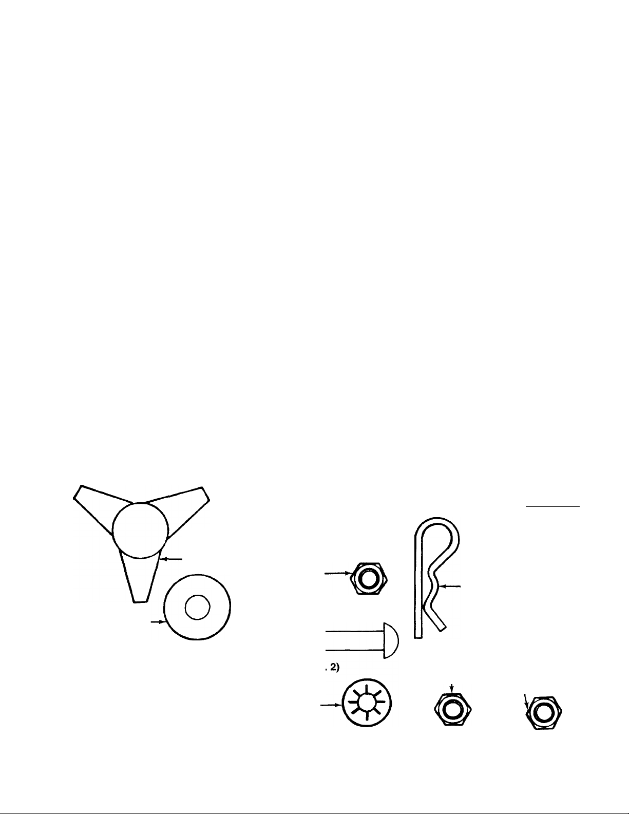
CONTENTS OF HARDWARE PACK
(Hardware pack may contain extra items which are not used on your unit. Quantities of parts and part
number > are shown in parentheses.)
ATTACHING THE NOZZLE AND
AIR DUCT ASSEMBLY
Hand Knobs
(720-0170)
Cupped
Washers (Qty. 3)
(736-0242)
Flat
Washers (Qty. 2)
(736-0231)—
©
(Qty. 3)
i ATTACHING THE
B
UPPER HANDLE
1
Hex Bolts 1/4-20 x
1-3/4" Long (Qty. 4)
(710-0136)
He:t Lock Nuts
1/4-20 Thread
(Qty. 4)
(712-0107)
INSTALLING THE BAG
ET
I
Stu d Pins (Qty
T
(711-0737)
Push-On
Speed Nuts
(Qty. 2)
(1539-019)
ATTACHING THE CLUTCH ROD (Self-Propelled Units Only)
Clutch Grip and Extension^
Spring are Not Shown L )
Clevis Pin
(Qty. 1)
(711-0679)-
Hairpin Clip
(Qty. 1)
(714-0145)
Hex Lock
Nut 1/4-20 Thread
(Qty.1)
(712-0107)
Hex Jam Nut
1/4-20 Thread
(Thinner Nut)
______
(Qty. 1)
(712-0298)
_
I I i I I I I I I I I I
0
INCHES
I
I I I I I I I I I I I
FIGURE 1.

ASSEMBLY INSTRUCTIONS
IMPORTANT: This unit is shipped WITHOUT
GASOLINE or OIL. After assembly, service engine
with gasoline and oil as instructed in the separate
engine manuai packed with your unit.
Upper
Nozzle :—-—Air
Duct
-Assembly
Directional
Discharge
Assembly
Impeller
Guard
Clutch
Rod
(Self-Propelled
Models Only)
FIGURE 2.-Loose Parts in Carton
C~*@
FIGURE 3.
NOTE: Reference to right or left hand side of the
vacuum is observed from behind the unit in the
operating position.
UNPACKING
Remove the vacuum, loose parts, hardware pack and
literature from the carton. Make certain all parts and
literature have been removed before the carton is dis
carded.
LOOSE PARTS IN CARTON
-(See Figure 2)
(1) Nozzle
(1) Upper Handle
(1) Air Duct Assembly
(1) Clutch Rod (Self-Propelled Models Only)
(1) Directional Discharge Assembly
(1) Impeller Guard
(1) Bag
TOW BAR KIT
Standard for push models, optional for self-pro
pelled models.
-(See Figure 3)
A (2) Hex Bolts 5/16-18 x 1” Long
B (4) Shoulder Spacers
C (2) Hex Nut 5/16-18 Thread
D (1) Truss Machine Screw 1/4-20 x 3/4” Long
E (1) Lock Washer 1/4” I.D.
F (1) Hex Nut 1/4-20 Thread
G (1) Shoulder Bolt
H (2) Cupped Washers 3/8” I.D.
I (1) Hex Jam Lock Nut 3/8-16 Thread
(2) Tow Bar Halves (Not Shown)
FIGURE 4.
Upper
Handle
FIGURE 5.
Nozzle
AHACHING THE NOZZLE (Hardware A)
Place nozzle in position on front of housing so that it
rests in flanges. Secure with one hand knob and
cupped washer (cupped side of washer against the
-nozzle). See figure 4.
/ / 7
ATTACHING THE UPPER HANDLE (Hardware B)
Place the upper handle in position over lower handle.
Fasten with four hex bolts and lock nuts provided.
-See figure 5. Two 7/16” wrenches are required.

Hand
Knob
FIGURE 6.
Cupped
.Washer
ATTACHING THE AIR DUCT ASSEMBLY (Hardware A)
Place air duct assembly over opening on top of hous
ing. Secure with two flat washers, cupped washers
(cupped side of washers against flat washers) and
-hand knobs. See figure 6.
FIGURE 7.
Stud Pin
Handle
INSTALLING THE BAG (Hardware C)
1. Place the stud pins in holes in upper handle
(head of pins go to the inside of handle). Secure
pins with push-on speed nuts by holding speed
nut with box wrench and tapping pin with ham-
------
mer. See figure 7.
2. Assemble the bag by slipping the top straps on
bag over upper handle. Hook two small straps
over stud pins on handle. Slip elastic opening of
bag over air duct assembly. Be certain elastic on
bag is placed over the flanges on air duct assem-
-----
bly. See figure 8.
FIGURE 8.
 Loading...