

Page 1
$1.00
K
owicirs GUIDE
• ASSEMBLY • OPERATION • MAINTENANCE • PARTS •
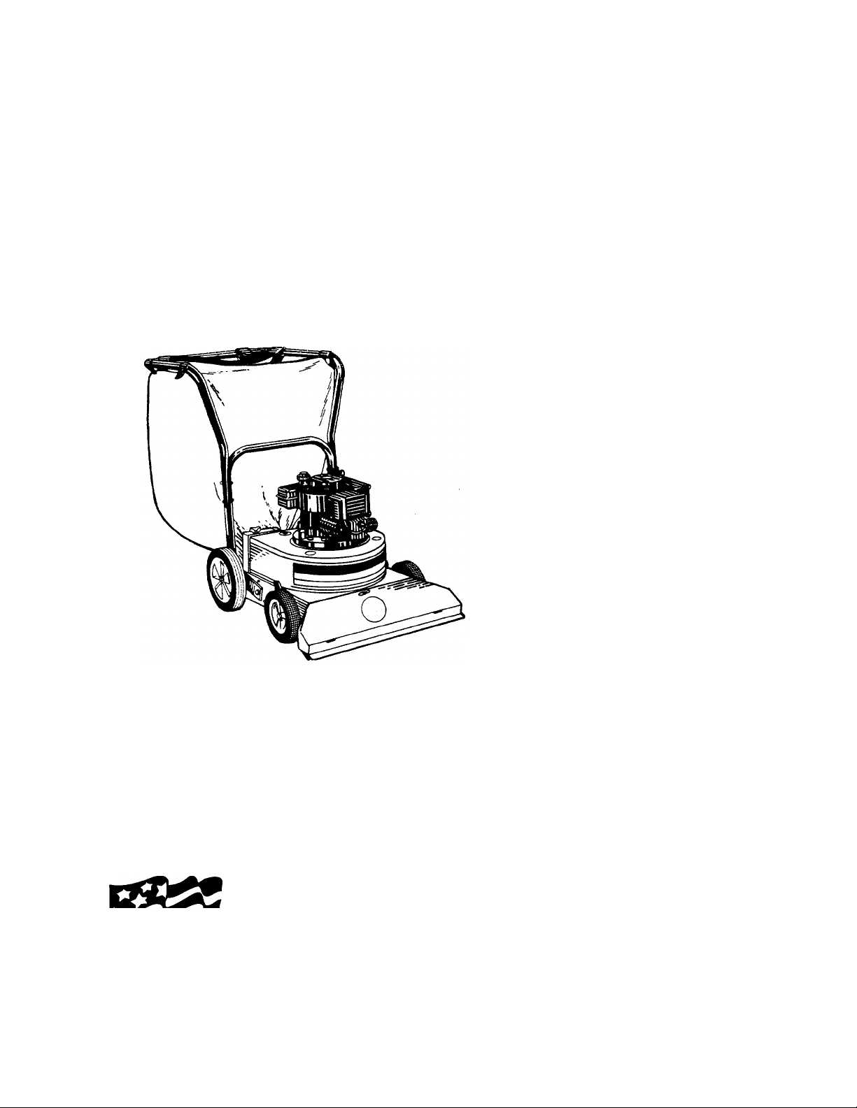
POWER
VACUUMS
Important:
Read Safety Rules
and Instructions Carefully
WARNING: This unit is equipped with an internal combustion engine and shouid not be used
on or near any unimproved forest-covered, brush-covered or grass-covered land unless the
engine’s exhaust system is equipped with a spark arrester meeting applicable local or state
laws (if any), if a spark arrester is used, it should be maintained in effective working order by
the operator.
in the State of California the above is required by law (Section 4442 of the California Public
Made ^
in
AMERICA
Resources Code). Other states may have simiiar iaws. Fédérai laws apply on federal lands.
A spark arrester for the muffler is available through your nearest engine authorized service
dealer or contact the service department, P.O. Box 360900, Cleveland, Ohio 44136.
Model Numbers
242-660-000
242-662-000
242665
IMPORTANT!
Record the Model No. and Mfg. Code which
appear on your unit in the space below. You
must have these numbers, along with the date
of purchase, in order to receive warranty or ser
vice.
MEETS ANSI SAFETY STANDARDS
MODEL NO. MFG. CODE
FORM NO. 770-5207G
Page 2
IMPORTANT
THIS SYMBOL POINTS OUT IMPORTANT SAFET' INSTRUCTIONS WHICH, IF NOT FOLLOWED, COULD ENDANGER THE
PERSONAL SAFETY AND/OR PROPERTY OF YOURSELF AND OTHERS. READ AND FOLLOW ALL INSTRUCTIONS IN THIS
▲
MANUAL BEFORE ATTEMPTING TO OPERATE \OUR POWER VACUUM. FAILURE TO COMPLY WITH THESE INSTRUC
TIONS MAY RESULT IN PERSONAL INJURY. WHE N YOU SEE THIS SYMBOL- ^ HEED ITS WARNING.
Your power vacuum was juilt to be operated according to the rules for safe operation in this manu-
DANGER: al. As with any type of po ver equipment, carelessness or error on the part of the operator can result
A
in serious injury. If you vi( ilate any of these rules, you may cause serious injury to yourself or others.
RULES FOR SAFE OPERATION
A
1. Read this operating and service instruction manual carefull;'. Be thor
oughly familiar with the controls and proper use of the po /ver vacu
um.
2. Never allow children to operate this power vaccum.
3. Keep the area of operation clear of all persons, particul irly small
children and pets.
4. Check fuel before starting engine. Do not fill fuel tank indc ors, when
engine is running, or while engine is hot. Wipe off any s Dilled fuel
before starting engine.
5. Do not change engine governor settings.
6. Do not put hands near rotating parts for any reason.
7. If the power vacuum should start to vibrate abnormally stop the
engine and check immediately for the cause. Vibration is g snerally a
warning of trouble.
8. Before cleaning, repairing or inspecting, make certain £ll moving
parts have come to a complete stop. Disconnect spark plui i wire and
keep wire away from plug to prevent accidental starting. \lso keep
throttle control lever in the stop position.
9. If the power vacuum should become blocked with debris at any point,
shut engine off and wait until the impeller comes to a com alete stop
before attempting to remove the obstruction. Disconnect s park plug
wire to prevent accidental starting.
10. Check all bolts for tightness at frequent periods.
11. Never store this power vacuum with fuel in the tank. Allow engine to
cool before storing in any enclosure.
12. Keep bag and equipment free of debris when not in use.
Never operate this power vacuum unless air duct and vacuum bag
13,
are properly affixed in their places. Large zippered end of bag must
be closed when operating to prevent objects from being blown out.
14.
Never empty vacuum bag when engine is running.
Never change auxiliary hose attachment when engine is running.
15.
16. The manufacturer recommends that the operator wear safety glass
es or some other suitable eye protection when operating this
machine.
17.
Check the vacuum bag frequently for wear and replace when neces
sary.
18,
Never operate as a leaf blower unless deflector assembly (optional
equipment) is properly affixed in its place.
19.
Exercise caution whenever operating as a leaf blower. Do not allow
discharge to be pointed in the direction of persons.
20,
No one should operate this unit while intoxicated or while taking
medication that impairs the senses or reactions.
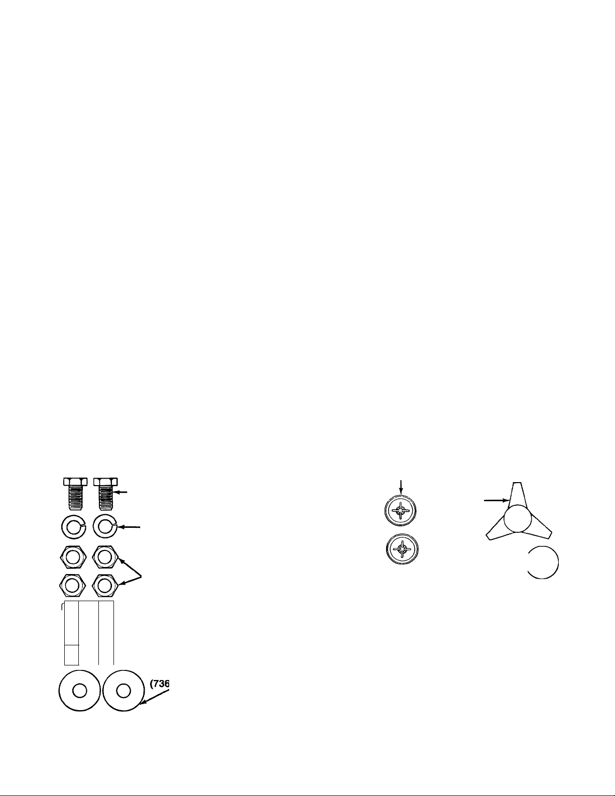
CONTENTS OF HARDWARE PACK
Hardware pack may contain extra ite ns which are not used on your unit. Hardware is shown
approximately one-half size. Quantiti }s of parts and part numbers are shown in parentheses.
ATTACHING THE
LOWER HANDLE
J L
n
■
•===
Hex Bolts
-3/8-16 X 1-1/2"
Long
(710-0344)
-Lock Washers
3/8" I.D.
(736-0169)
Hex Nuts
3/8-16 Thread
(712-0798)
Hex Bolts
3/8-16 X 3/4"
Long
(710-0201)
Cupped Washers
3/8" I.D.
-0331)
ATTACHING THE
B
REAR WHEELS
Wheel Spacers
-f—1/2" I.D.
(750-0588)
I
____
I
Flat Washers
1/2" I.D. x1" O.D.
(736-0272)
@@@@
AT ACHING THE UPPER HANDLE
mp irri ozn azp
Hex Bolts 1/4-20 x
1-3/4" Long
-
-----
(710-0136)
Hex Lock Nuts
1/4-20 Thread
(712-0107)
Push Caps
(726-0128)
ATTACHING THE
AIR DUCT ASSEMBLY
Hand Knob
(720-0170)
Cupped
Washer 5/16" I.D.—W Q
(736-0242) ^
ATTACHING THE BAG
✓ —X Push-On
-Stud Pins
(711-0737)
—Speed Nuts
(1539-019)
I I
0
INCHES
I
I I I
I
I I I
I
I I I
I
I I I
I
I I I
I
I I
FIGURE 1.
Page 3
ASSEMBLY INSTRUCTIONS
\ IMPORTANT: This unit is shipped WITHOUT
GASOLINE or OIL. After assembly, service engine
with gasoline and oii as instructed in the separate
engine manual packed with your unit.
Upper Handle ,Bag
Rear
Wheels
Air Duct
Assembly
FIGURE 1.
NOTE: Reference to right or left hand side of the
vacuum is observed from behind the unit in the
operating position.
TOOLS REQUIREO FOR ASSEMBLY
(2) 9/16" Wrenches
(2) 7/16" Wrenches
(1) Hammer or Rubber Mallet
UNPACKING
Remove the vacuum, loose parts, hardware pack and
literature from the carton. Make certain all parts and
literature have been removed before the carton is dis
carded.
-LOOSE PARTS IN CARTON (See figure 1)
(1) Upper Handle
(1) Lower Handle
(1) Air Duct Assembly
(2) Rear Wheels
(1) Bag
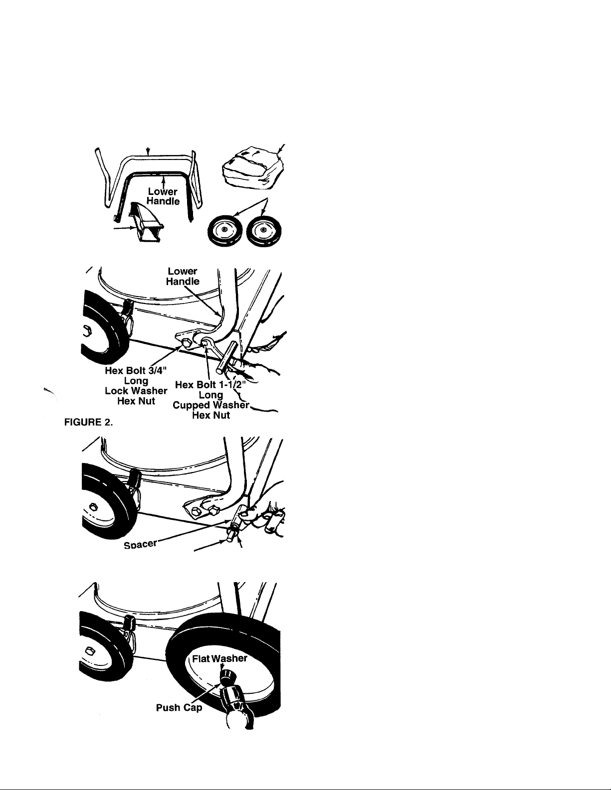
ATTACHING THE LOWER HANOLE (Hardware A)
1. Raise the back of the unit off the floor approxi
mately 3 inches and block it so that the lower
handle and rear wheels may be assembled.
2. Place lower handle in position on the vacuum, lin
ing up the holes in the handle with the holes on
-------
the frame. See figure 2. Place hex bolts 3/4" long
through lower hole in handle and frame. Secure
with 3/8" lock washers and hex nuts on the inside
of frame, finger tight only.
3. Place hex bolts 1-1/2" long through upper hole in
handle and frame. Secure with 3/8" cupped
washers (cupped side against the frame) and hex
nuts.
4. Tighten all four nuts and bolts using two 9/16"
wrenches.
FIGURE 3.
FIGURE 4.
Axle''
Shaft
Flat
Washer
-ATTACHING THE REAR WHEELS (Hardware B)
1. Slide spacers onto the axle shafts. Place one flat
washer on each shaft next to the spacers. See
figure 3.
2. Place rear wheels in position on the shafts, then
another flat washer. Secure with black push cap
by placing the push cap in position and tapping
— on with hammer or rubber mallet. See figure 4.
Page 4

FIGURE 5.
Upper
—Handle
Hex Bolt s
Hex Loc i
Nuts
Low sr
Handle
Air Duct
Assembly
ATTACHING THE UPPER HANDLE (Hardware C)
Place the upper handle in position over lower handle.
Fasten with four hex bolts 1-3/4" long and hex lock
-nuts. See figure 5. Two 7/16" wrenches are required.
ATTACHING THE AIR DUCT ASSEMBLY
(Hardware D)
1. Place the tabs on the air duct assembly into the
--------
slots in the frame as shown in figure 6. Raise the
air duct into position.
FIGURE 7.
Secure air duct with hand knob and cupped
washer. Cupped side of washer must be against
■ the air duct. See figure 7.
ATTACHING THE BAG (Hardware E)
1. Place the stud pins in holes in upper handle
(head of pins go to the inside of handle). Secure
pins with push-on speed nuts by holding speed
nut with box wrench and tapping pin with ham-
------
mer. See figure 8.
Page 5

k Air Duct Assembly
FIGURE 10.
2. Attach the bag by slipping the top straps on the
bag over upper handle. Hook the two small straps
— over the stud pins on handle. See figure 9.
3. Slip the elastic opening of the bag over the air
duct assembly, making certain the elastic opening
is secured behind the flanges on all four sides of
— the air duct. See figure 10.
Flange On
OPERATION
BEFORE STARTING ENGINE
Service engine with gas and oil. See engine manuai
packed with vacuum for complete instructions for care
and maintenance of engine. Read directions carefully.
WARNING: Revolving blades — keep
A
TO START ENGINE
After the engine has been properly fueled and oiled
(refer to engine operating and maintenance instruc
tions), start engine as follows.
1. Move throttle control lever on engine to FAST or
2. Crank engine by puiiing recoil starter with a quick,
3. After two or three full firm pulls on recoil (or as
hands away from all openings.
START position.
firm stroke. Do not pull out so far the rope stops
with a jerk. Do not aliow rope and handie to snap
back into piace.
soon as engine fires), move throttle control to
RUN position.
TO STOP ENGINE
1. To stop engine, move throttle control lever to OFF
position.
2. Disconnect spark plug wire and ground to prevent
accidentai starting while equipment is un
attended.
TO EMPTY BAG
The bag may be emptied using the iarge zipper as
shown in figure 11. Be certain the zipper is closed
when operating the unit.
FIGURE 11.
Page 6

ADJUSTMENTS
WARNING: Do not at any time m ike any
adjustment to the unit without fir st stop-
A
HEIGHT ADJUSTMENT
An adjusting plate and thumb lever at both front
wheels provide height adjustment for the vacuum.
See figure 12. Each adjusting plate has nine posi
tions. Height will be changed when the thumb lever Is
moved from one position to another. Simply depress
thumb lever towards wheel and move wheel aid lever
assembly to desired position. Both wheels must be
placed in the same relative position. Lower th€ front of
the unit to obtain more suction.
ping engine and disconnectin<| spark
plug wire.
CARBURETOR ADJUSTMENT
WARNING: If any adjustments are made
to the engine while the engine is running
A
Minor carburetor adjustment may be required to com
pensate for differences in fuel, temperature, altitude
or load.
NOTE: A dirty air cleaner will cause engine to run
rough. Be certain air cleaner is clean and attached to
the carburetor before adjusting carburetor.
Do not make unnecessary adjustments. Factory set
tings are satisfactory for most applications and condi
tions. If adjustment is needed, refer to the separate
engine manual packed with your vacuum.
(e.g. carburetor), keep clear of all moving
parts. Be careful of heated surfaces and
muffler.
MiMNTENANCE
WARNING: Always stop engine arid dis
connect spark plug wire before cl waning,
A
LUBRICATION
Wheels—The wheels require no lubrication. How
ever, if the wheels are removed for any reason, lubri
cate the surface of the axle bolt and the inner surface
of the wheel with light oil. A 4 oz. plastic bottle of light
oil lubricant is available. Order part number 737-0170.
Engine oil may also be used.
ENGINE
Refer to the separate engine manual for engine
maintenance instructions.
Maintain engine oil as Instructed in the S(}parate
engine manual packed with your unit. Read and follow
instructions carefully.
lubricating or performing any repairs or
maintenance.
OFF-SIEASON STORAGE
The following steps should be taken to preps re your
vacuum for storage.
1. Clean and lubricate the vacuum thcrcughly as
described in the lubrication instructions.
2. Refer to engine manual for correct engine storage
instructions.
Service air cleaner every 25 hours under normal con
ditions. Clean every few hours under extremely dusty
conditions. Poor engine performance and flooding
usually indicates that the air cleaner should be ser
viced. Tc service the air cleaner, refer tc the separate
engine manual packed with ycur unit.
The spark plug should be cleaned and the gap reset
once a seascn. Spark plug replacement is recom
mended at the start of each season; check engine
manual for correct plug type and gap specifications.
Clean the engine regularly with a cloth or brush. Keep
the cooling system (blower housing area) clean to
permit proper air circulation which is essential to
engine performance and life. Be certain to remove all
dirt and combustible debris from muffler area.
3. If storing in an unventilated or metal storage
shed, coat metal parts with a light oil or silicone to
prevent rust.
4. Store in a dry, clean area. Do not store next to
corrosive materials, such as fertilizer.
Page 7

Models 660, 662 and
OPTIONAL EQUtPMENT
242665
Hose Attachment Kit Model 290-210-000 and
Blower Conversion Kit Model 290-211-000 are
available as optional equipment.
Blower
Aiiacnmeni mi
Model 290-210-000
Conversion Kit
Model 290-211-000
Page 8

PARTS LIST FOR MODE LS 660, 662 AND 242665 POWER VACUUMS
REF.
NO.
10 15780 638 Vacuum Deck Ass’y.
11
12
13 15790 Wiper Retaining Strip 42 764-0208A
14
15 735-0222 Nozzle Wiper Rear 44
16
17
18 738-0102
19 734-1139 Front Wheel Ass’y. Conp.
20
21 15262B
22 15261A Index Plate
24
25
PART
NO.
1 749-0664
2
—
3 710-0260
4
15784
710-0654A
5
6 15786A
7 736-0217
8
710-0591 Hex Bolt 3/8-24 X 1.0" l.g.
CODE
638
DESCRIPTION
Upper Handle
Engine 27
Carriage Bolt 5/16-18 x .62" Lg.*
Blower Housing Ass’y. X .06"
Hex Tap Scr. 3/8-16 x ' .0" Lg.
Impeller Ass’yL-Wash. 3/8" I.D.* 34
w/Patch
9 722-0137
P.V.C. Foam Strip-12"
15796 Front Baffle Ass’y. 40 712-0113
15788 Lower Baffle Ass’y. 41
REF.
NO.
26 738-0507B
28
PART
NO.
728-0128
736-0272
CODE
Shoulder Bolt .5" Dia. x 7/16" Lg.
Push Cap .5" Rod (Black)
FI-Wash. 1/2" I.D. X 1.0" O.D.
29 734-1140 Rear Wheel Ass’y. Comp.
31
750-0588 Wheel Spacer 1/2" I.D. x 15/16"
15779 Air Duct Ass’y.
35 710-0201 Hex Bolt3/8-16x.75"*
36 710-0344
Hex Bolt 3/8-16x1.5’’*
38 720-0170 Hand Knob
712-0107
39
Hex L-Nut 1/4-20 Thd.
Wing Nut 1/4-20 (Plastic)
710-0136 Hex Bolt 1/4-20 X 1.75"*
Vacuum Bag (6.6 Bushel)
728-0123
Pop Rivet .188" Dia. 43
749-0592
Lower Handle
14578 Height Adj. Ass’y. Comp.-R.H.
712-0267
Hex Nut 5/16-18 Thd.*
14579
Height Adj. Ass’y. Comp.-L.H.
736-0242 Bell-Wash. .34" I.D. x .fi7" O.D. (Not Shown)
Shid. Bolt .498" Dia. x 1.45" Lg. 45 1539-019 Push Speed Nut .25" Dia.
711-0737 Stud Pin .25" Dia. x 1.75" Lg.
736-0331
Bell-Wash. .39" I.D. x 1 12" O.D. 47
Wheel Pivot Bar 48
712-0798 Hex Nut 3/8-16 Thd.* 50
14832
Spring Lever Ass’y. w/H ,nob 51 736-0169 L-Wash. 3/8" I.D.*
46
714-0105
735-0221
49 15789
710-0302
Sq. Key 3/16" X 1" Lg.
Nozzle Wiper Side
Wiper Retaining Strip
Hex Self-Tap Scr. #10
DESCRIPTION
'For faster service obtain standard nuts, boits and washe s iocaliy.
If these items cannot be obtained locaiiy, order by par: number
and size as shown on parts list.
CODE; N notates a new part (not previousiy existing). A three digit
number is the color code. Specify coior code if coior or finish is
important when ordering parts, [i.e., (part no.)-638 for Red
Finish].
(638—Red) (498—Yeiiow)
TROUBLE SHOOTING
PROBLEM POSSIBLE CAUSE(ii) CORRECTIVE ACTION
Engine fails to start 1. Fuei tank empty, c r stale fuel.
2. Spark plug wire disconnected.
3. Faulty spark plug.
Loss of power;
operation erratic
1. Spark plug wire loi >se.
2. Blocked fuel line (i ’ so equipped)
or stale fuel.
3. Water or dirt in fue 1 system.
4. Carburetor out of < idjustment.
5. Dirty air cleaner.
Engine overheats
Too much vibration
1. Carburetor not adj jsted
properly.
2. Engine oil level lov/.
Loose parts or dar laged
crankshaft.
. — /
Unit does not X
discharge /
1. Directional dischaige clogged.
2. Foreign object lodijed in air vane
plate assembly.
1. Fill tank with clean, fresh fuel.
2. Connect wire to spark plug.
3. Clean, adjust gap or replace.
1. Connect and tighten spark plug wire.
2. Clean fuel line; fill tank with clean
fresh gasoline.
3. Disconnect fuel line at carburetor to drain fuel
tank. Refill with fresh fuel.
4. Adjust carburetor.t
5. Service air cleaner.f
1. Adjust carburetor.t
2. Fill crankcase with proper oil.
Stop engine immediately and disconnect
spark plug wire. Tighten all bolts and nuts.
Make all necessary repairs. If vibration continues,
have unit serviced by an authorized service
dealer.
1. Stop engine immediately and disconnect
spark plug wire. Clean directional discharge.
2. Stop engine immediately and disconnect
spark plug wire. Remove lodged object.
tRefer to the engine manual packed with your unit.
NOTE: Fo/repairs beyond the minor adjustments listed above, please contact your nearest authorized service dealer.
FOR REPLA CEMENT PARTS, CONTACT:
SERVICE DEPARTMENT • FlO. BOX 360900 • CLEVELAND, OHIO 44136
 Loading...