

Page 1
OMiNBrS GUIDE
• ASSEMBLY • OPERATION • MAINTENANCE • PARTS •
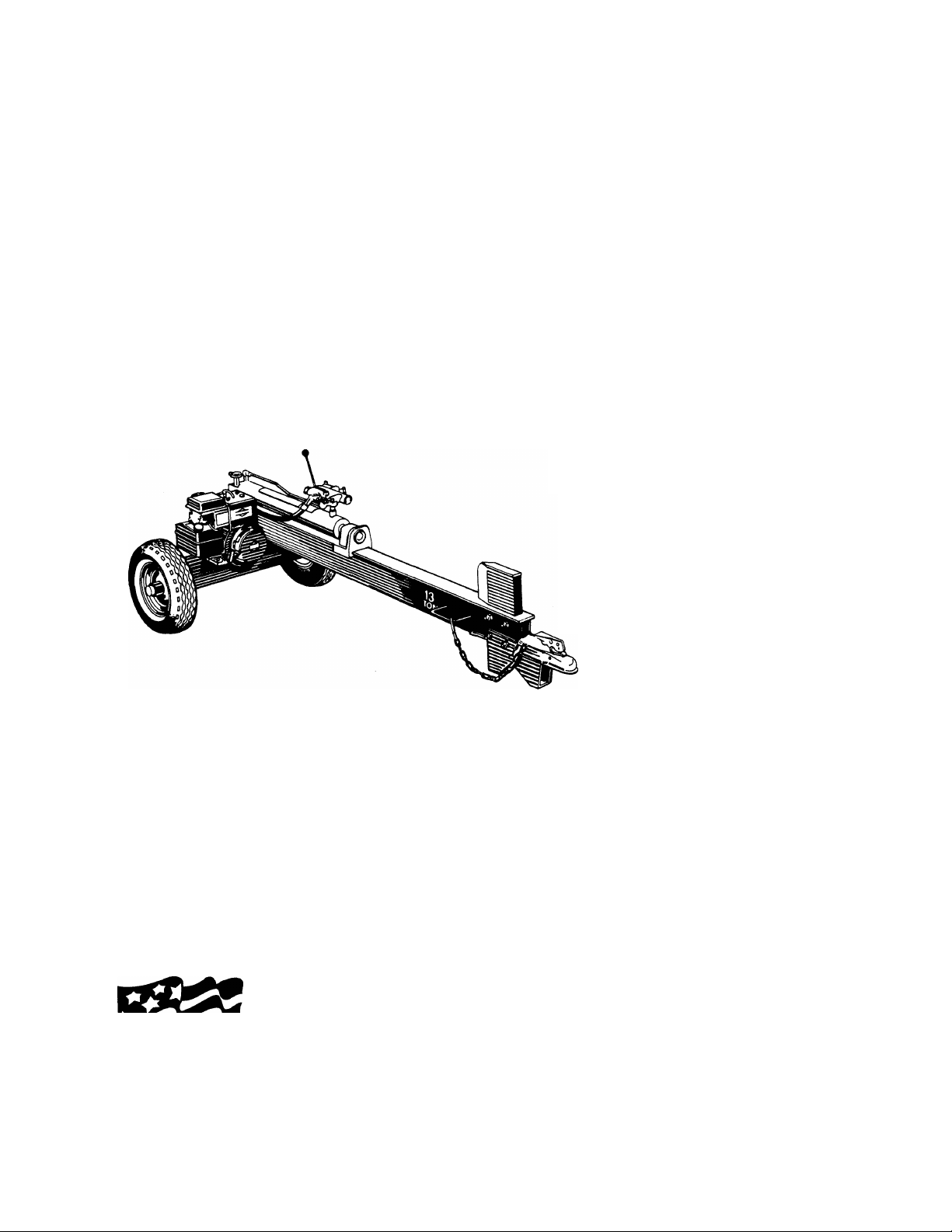
13 TON
HORIZONTAL
LOG SPLITTER
$1.00
Important:
Read Safety Rules
and Instructions Carefully
WARNING: This unit is equipped with an internal combustion engine and should not be used
on or near any unimproved forest-covered, brush-covered or grass-covered land unless the
engine’s exhaust system is equipped with a spark arrester meeting applicable local or state
laws (if any). If a spark arrester is used, it should be maintained in effective working order by
the operator.
In the State of California the above is required by law (Section 4442 of the California Public
Made ^
in
AMERICA
Resources Code). Other states may have similar laws. Federal laws apply on federal lands.
A spark arrester for the muffler is available through your nearest engine authorized service
dealer or contact the service department, P.O. Box 360900, Cleveland, Ohio 44136.
Model Number
242-610-000
IMPORTANT!
Record the Model No. and Mfg. Code which
appear on your unit in the space below. You
must have these numbers, along with the date
of purchase, in order to receive warranty or ser
vice.
MEETS ANSI SAFETY STANDARDS
MODEL NO. MFG. CODE
FORM NO. 770-6744G
Page 2
A
IMPORTANT
RULES FOR SAFE OPERATION
THIS SYMBOL POINTS OUT IMPORTANT SAFETY INSTRUCTIONS WHICH, IF NOT FOLLOWED, COULD ENDANGER THE PERSON
AL SAFETY AND/OR PROPERTY OF YOURSELF AND OTHERS. READ AND FOLLOW ALL INSTRUCTIONS IN THIS MANUAL BEFORE
ATTEMPTING TO OPERATE YOUR LOG SPLITTER. FAILURE TO COMPLY WITH THESE INSTRUCTIONS MAY RESULT IN PERSON
AL INJURY. WHEN YOU SEE THIS SYMBOL— A HEED ITS WARNING.
A
A
ik
Your log splitter was built to be operatec according to the rules for safe operation in this manual. As with
any type of power equipment, carelessness or error on the part of the operator can result in serious
injury. If you violate any of these rules, \ou may cause serious injury to yourself or others.
TRAINING
Before operating this splitter, read and understand this manual
1.
completely. Become familiar with it for your own safety. To fail
to do so may cause serious injury. Do not aliow anyone to
operate your splitter who has not read this manjal. Keep this
manual in a safe place for future and regular ref( rence and for
ordering replacement parts.
Never use your splitter for any other purpose than splitting
wood. It is designed for this use and any other ise may cause
an injury. Your log splitter is a precision piece of power equip
ment, not a playtoy. Therefore, excercise extremi caution at all
times.
Never allow children to operate your log splitter
3.
adults to operate it without proper instruction,
well acquainted with these rules of safe operat
allowed to use your log splitter.
Only the operator is to be near your log splitti
4.
Keep all others, including pets and children, a n
feet away from your work zone. Flying wood can
If a helper is assisting in loading logs, never ac
trol until the helper is clear of the area. More a<
when more than one person operates the log i
any other time.
No one should operate this unit while intoxicate
5.
ing medication that impairs the senses or reai
mind is essential for safety. Never allow a perse
or otherwise not alert to use your splitter.
Do not allow
Only persons
on should be
ir during use.
inimum of 20
be hazardous,
ivate the con;cidents occur
plitter than at
f or while tak:tions. A clear
n who is tired
DANGER
A
8. Only operate your splitter on level ground and not on the side
of a hill. It could tip, or rolling logs or poor footing could cause
an accident. Operating the splitter on level ground also pre
vents the spillage of gasoline from the fuel tank.
9. Never attempt to move the log splitter over hilly or uneven ter
rain without a tow vehicle or adequate help.
10. Always block the wheels to prevent movement of log splitter
while in operation.
11. Check the fuel before starting the engine. Gasoline is an
extremely flammable fuel. Do not fill the gasoline tank indoors,
when the engine is running, or while the engine is still hot.
Replace gasoline cap securely and wipe off any spilled gasoline
before starting the engine as it may cause a fire or explosion.
12. Both ends of each log must be cut as square as possible to
help prevent the log from riding out of the splitter during oper
ation.
OPERATION
1. Stand behind the ram when operating. See illustration.
A
PREPARATION
Never wear loose clothing or jewelry that can be caught by
1.
moving parts of your log splitter and pull you into it. Keep
clothing away from all moving parts of your log ¡plitter.
Wear proper head gear to keep hair away from moving parts.
2.
Always wear protective hearing devices as needi d.
Always wear safety shoes. A dropped log can ; eriously injure
3.
your foot.
Always wear safety glasses or goggles while operating your
splitter. A piece of splitting log could fly off and lit your eyes.
If you wear gloves, be sure they are tight fittinc) without loose
cuffs or draw strings.
Use your log splitter in daylight, or under good c rtificial light.
Never operate your splitter on slippery, wet, middy or icy sur
faces. Safe footing is essential in preventing accidents. Never
operate your splitter while attached to a towing ’'ehicle.
Page 3

2. Know how to stop the unit and disengage the controis.
3. Never piace hands or feet between iog and splitting wedge or
between log and ram during forward or reverse stroke. To do
so may result in crushed or amputated fingers or toes, or
worse, you may lose an arm or foot.
4. Do not straddle the splitter when using it. A slip in any position
could result in a serious injury.
5. Do not step over your log splitter when the engine is running.
You may trip or accidentally activate the ram if you step over. If
you need to get to the other side, walk around.
6. Never try to split two logs on top of each other. One may fly
out and injure you.
7. When loading the log splitter, place your hands on the side of
the log, not at the ends. Never attempt to load your splitter
while the ram is in motion. You may get caught by the ram and
injured.
8. Only use your hand to operate the ram or control lever. Never
use your foot or a rope or any other extension device. This
could result in your ability to stop your splitter quickly enough
and cause injury.
9. Always keep fingers away from any cracks that open in the log
during splitting operation. They can quickly close and pinch or
amputate your fingers.
10. Never attempt to split woods across the grain. Some types of
wood may burst or fly out of your splitter and result in injury to
you or a bystander.
11. For logs that are not cut square, the longest portion of the log
should be rotated down and the most square end placed
against the ram.
12. Keep your work area clean. Immediately remove split wood
around your splitter so that you do not stumble over it.
13. Never move the log splitter while the engine is running.
14. Never leave your log splitter unattended with the engine run
ning. Shut off the engine if you are leaving your splitter, even
for a short period of time. Someone could accidentally activate
the ram and be injured.
15. Do not run engine in an enclosed area. Exhaust gases contain
carbon monoxide. This odorless gas can be deadly when
inhaled.
16. Be careful not to touch the muffler after the engine has been
running as it is HOT.
17. If the equipment should start to vibrate abnormally, stop the
engine and check immediately for the cause. Vibration is gen
erally a warning of trouble.
18. When cleaning, repairing or inspecting, make certain all mov
ing parts have stopped. Disconnect the spark plug wire and
keep the wire away from the plug to prevent accidental start
ing.
3. Replace all damaged or worn parts such as hydraulic hoses
and fittings immediately with manufacturer approved replace
ment parts.
4. Do not change the engine governor settings or overspeed the
engine. This increases the hazard of personal injury. The maxi
mum engine speed is preset by the manufacturer and is within
safety limits.
5. Do not alter your splitter in any manner such as attaching a
rope or extension to the control lever or adding to the width or
height of the wedge. Such alterations may cause your splitter
to be unsafe.
6. Perform all recommended maintenance procedures before you
use your splitter.
7. Do not service or repair your log splitter without disconnecting
the spark plug wire.
8. Never store the equipment with gasoline in the tank inside of a
building where ignition sources are present, such as hot water
and space heaters, clothes dryers and the like. Allow the
engine to cool before storing in any enclosure.
9. Always store gasoline in an approved, tightly sealed container.
Store the container in a cool, dry place. Do not store in a build
ing where ignition sources are present.
10. To reduce fire hazard, keep engine free of grass, leaves, wood
chips, and excessive grease and oil.
11. The hydraulic system of your log splitter requires careful
inspection, along with the mechanical parts. Be sure to replace
frayed, kinked, or otherwise damaged hydraulic components.
12. Fluid escaping from a very small hole can be almost invisible.
Do not check for leaks with your hand. Escaping fluid under
pressure can have sufficient force to penetrate skin, causing
serious personal injury. Leaks can be located by passing a
piece of cardboard or wood over the suspected leak and look
ing for discoloration.
13. Should it become necessary to loosen or remove any hydraulic
fitting or line, be sure to relieve all pressure by shutting off the
engine and moving the control handle back and forth several
times.
14. Do not remove the cap from the hydraulic tank or reservoir
while your log splitter is running. Hot oil under pressure could
cause injury.
15. The pressure relief valve on your splitter is preset at the facto
ry. Do not adjust the valve. Only a qualified service technician
should perform this adjustment.
16. Completely drain fuel tank prior to storage. This guards against
accumulation of fuel fumes which could result in a fire hazard.
17. Never store log splitter outside without a waterproof cover.
Rain will cause rust on the inside of the cylinder.
A
MAINTENANCE
1. Do not operate your splitter in poor mechanical condition or
when in need of repair.
2. Periodically check that all nuts, bolts, screws, hose clamps and
hydraulic fittings are tight to be sure equipment is in safe
working condition. Where appropriate, check all safety guards
and shields to be sure they are in the proper position. Never
operate your splitter with safety guards, shields or other pro
tective features removed. These safety devices are for your
protection.
A
TOWING
1. This unit should not be towed on any street, highway or public
road. Any licensing needed to comply with the existing federal,
local or state vehicle requirements is the sole responsibility of
the purchaser.
2. Before towing, be certain the log splitter is correctly and
securely attached to the towing vehicle, and the safety chains
are in place. Leave slack in chains for turning allowance.
3. Do not allow anyone to sit or ride on your splitter. They can
easily fall off and be seriously injured.
Page 4
ASSEMEtLY INSTRUCTIONS
IMPORTANT: This unit has been shipped without
gasoiine or oii in the engine. After assembly, refer
to separate engine manuai for proper fuei and
engine oii information.
Q
Q
DE-
■K
H
L-
M-
FiGUREt
UNPACKING
Remove the log splitter and loose parts from the car
ton by cutting the corners of the carton. Make certain
all parts and literature have been removed from the
carton before the carton is discarded.
Loose Parts in Carton:
(1) Axle Assembly
(1) Tow Hitch Assembly
(1) Beam Stand
(1) Tow Hitch Chain
(1) Hardware Pack
(1) Wheel Bearing Pack (Includes 4 roller bearings,
2 grease seals and 2 hub caps)
Contents of Hardware Pack (See Figure 1):
A
B
C
D
E
F
G
H
Hex Bolts 3/8-24 x 1" Long (Fine Thread)
(4)
Lock Washers 3/8" I.D.
(5)
Hex Nuts 3/8-24 (Fine) Thread
(4)
Spacers 3/4" I.D. x 1-1/2" Long
(2)
Castle Nuts 3/4-16 Thread
(2)
Cotter Pins
(2)
Hex Bolt 3/8-16 X 4-1/2" Long (Coarse Thread)
(1)
Flat Washers 3/8" I.D.
(2)
Spacers 3/8" I.D. x 5/8" Long
(2)
Hex Nut 3/8-16 (Coarse) Thread
(1)
Hex Bolt 3/8-16 X 3-1/4" Long (Coarse Thread)
(1)
Spacers 3/8" I.D. x 2" Long
(2)
Hex Lock Nut 3/8-16 (Coarse Thread)
(1)
Automotive Grease (not shown)
(1)
Tools Required for Assembly
(2) 9/16" Wrenches*
Flat Blade Screwdriver
(1)
Adjustable Wrenches
(2)
Pair of Pliers
(1)
Soft Hammer or Mallet
(1)
* Adjustable Wrenches may be used.
Other Materials Required for Assembly
Engine Oil
Unleaded Gasoline
Approximately 3 Gallons of Dexron II Automatic
Transmission Fluid
Axie
Assembiy
FIGURE 2.
Hex
\ Washer
^ (B)
t
Lock
Ergine
Fíame
Assembly
'^HexNjt
(C)
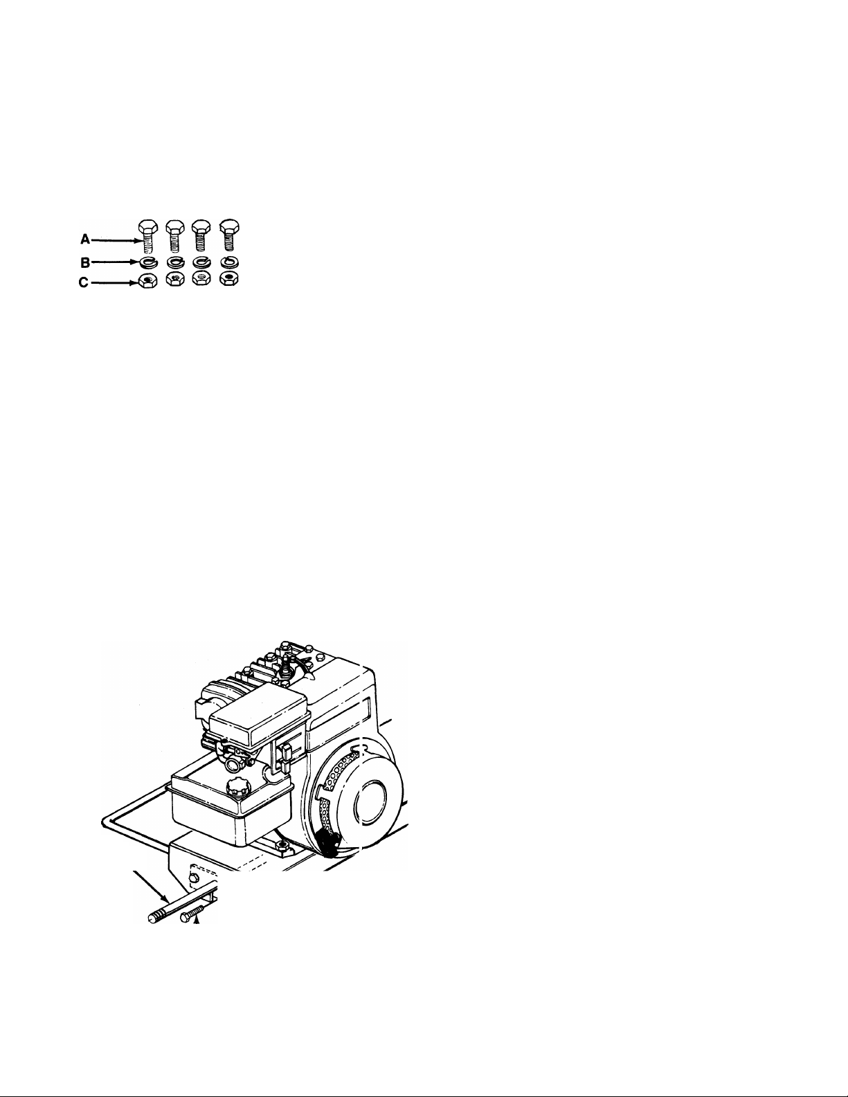
ATTACHING THE AXLE
1.
Block up the engine frame assembly.
— 2.
Place the axle assembly in position inside the
engine frame assembly as shown in figure 2.
Secure with 1" long fine thread hex bolts (A), four
3.
lock washers (B) and fine thread hex nuts (C),
using two 9/16" wrenches. Tighten securely.
4.
ends of the axles.
Page 5
Flat
Washer
(H)
FIGURE 5.
Spacer (L)
Hex Bolt (G)>
Flat Washer
Hitch
(H)
Chain
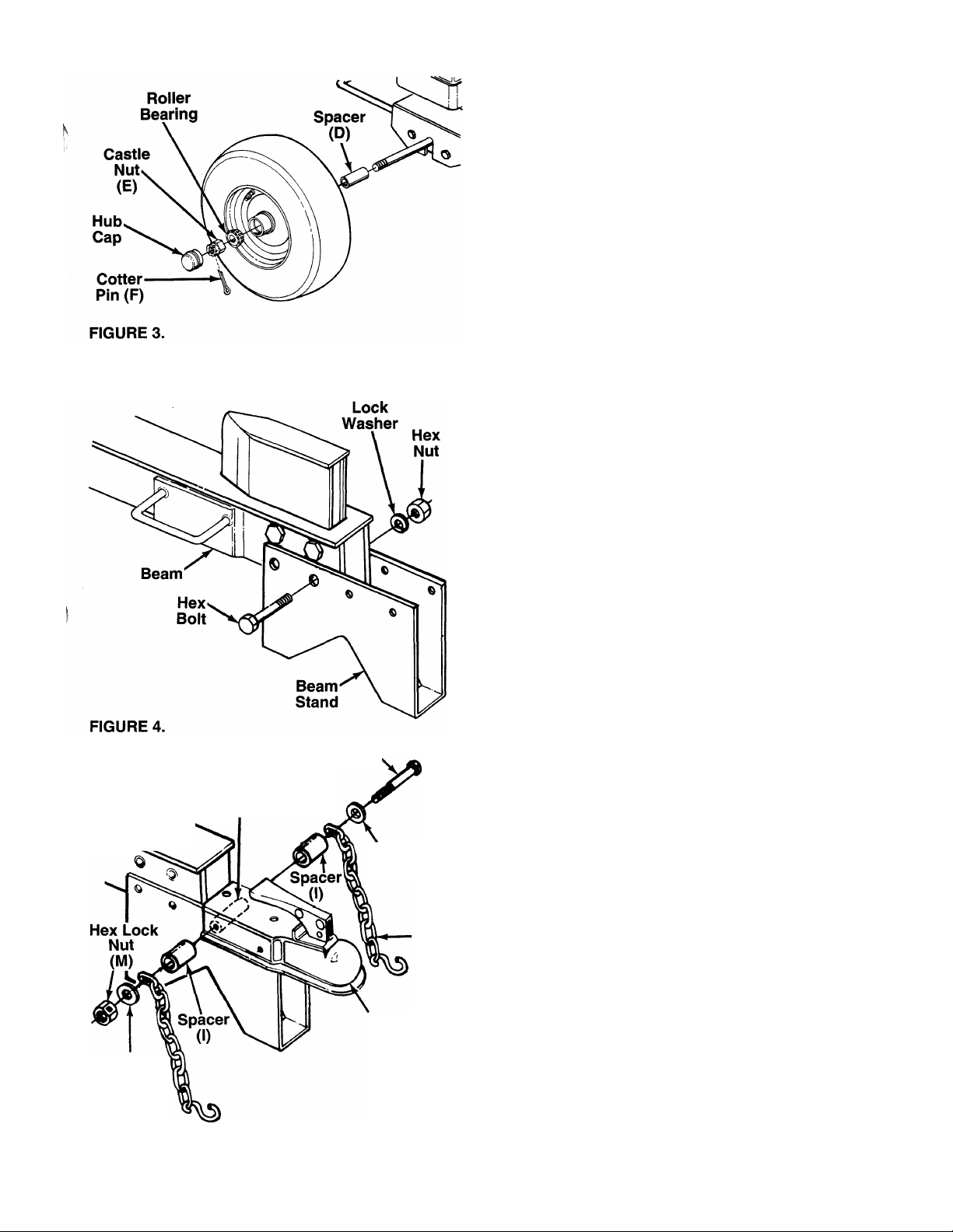
INSTALLATION OF WHEELS
1. Remove the roller bearings, grease seals and
hub caps from the plastic bag.
2. Pack the tapered roller bearings with wheel bear
ing grease, insert a bearing into the inside hub of
each wheel (valve stem is on the outside of the
wheel). Insert a grease seal into the inside hub of
each wheel. Tap on using a short hammer or mal
let.
NOTE: A large socket can be placed against the
grease seal to aid in properly seating the seal.
3. Place one spacer (D) on each axle, then one
___
wheel and a tapered roller bearing. See figure 3.
NOTE: Make certain tapered roller bearings were
packed with grease. Save any extra grease for greas
ing the beam under “Initial Preparation” on page 6.
4. Thread hex castle nuts (E) on axle. Using an
adjustable wrench, tighten castle nuts until snug,
then back off approximately 1/3 turn, or until one
of the slots on the castle nut lines up with hole in
axle.
5. Insert cotter pins (F) through slot in castle nuts
and holes in axle. Secure by bending the ends of
the cotter pins in opposite directions, using a pair
of pliers.
6. Place hub cap in position on wheel, and tap on
with a soft hammer or maliet.
ASSEMBLING THE BEAM STAND
-The wedge is already assembled to the log splitter,
and is heid in place with four 3-1/2” long hex bolts,
lock washers and hex nuts. The top two bolts and
nuts are tightened securely. The bottom two bolts and
nuts have been assembled loosely.
1. Remove the two bottom bolts, lock washers and
hex nuts from the beam and wedge.
2. Place the beam stand in position as shown in fig
ure 4. Secure to beam and wedge with hardware
just removed, using the larger holes in beam
stand. Tighten securely.
INSTALLING THE TOW HITCH
1. Attach the safety chain as follows.
a. Place one flat washer (H) on hex bolt 4-1/2"
long (G), then the end of one safety chain and
one spacer 5/8" long (I).
b. Place the hitch in positioin on the beam stand
-----------as shown in figure 5.
c. Place one spacer 2" long (L) inside beam
stand. Using hole closest to beam, insert the
hex bolt with hardware attached through hitch,
beam stand and spacer.
d. Place the other spacer 5/8" long (I) on hex bolt,
then the end of other safety chain and flat
washer (H). Secure with hex lock nut (M).
Page 6

FIGURE 7.
2. Place spacer (L) inside the beam stand. Insert
hex bolt (K) through forward hole in hitch, beam
— stand and spacer. Secure with lock washer (B)
and hex nut (J). See figure 6.
3. Tighten both bolts and nuts securely using two
9/16" wrenches.
ATTACHING THE CONTROL HANDLE
1. The bottom of the control handle is already
attached to the valve with a cotter pin. Remove
the second cotter pin and clevis pin which are
attached to the valve only.
2. Place the handle in position, and secure using
the clevis pin and cotter pin. Secure by bending
the ends of the cotter pin in opposite directions.
See figure 7.
FINAL ASSEMBLY
1. Make certain all nuts, bolts and hose clamps are
tightened securely.
2. Before operating the log splitter, make certain to
follow the “Initial Preparation” instructions in the
Operation Section.
OPERATION
INITIAL PREPARATION
1. Place the log splitter on a firm, level surface.
2. Service engine with gasoline anc oil as instructed in the separate engine manua packed with your log splitter.
3. Lubricate the area of the beam on which the ram
will slide with automotive grease.
4. Fill the reservoir tank (beam) and purgo the air
from the system as follows.
a. With the log splitter on a level surface remove
the cap from the breather tube. See figure 8.
Remove the fluid check plug from the end
plate.
b. Fill the reservoir tank with Dexron II automatic
transmission fluid until fluid starts to c ome out
of the hole. Replace the check plug.
c. Start the engine. Slowly move the cortrol han
dle forward and backward until the rai n moves
smoothly in both directions.
d. Stop the engine. Remove the fluid ch^ick plug.
Add fluid as necessary until fluid »tarts to
come out of the hole. Replace the check plug.
------- “
Breather
Tube
Fluid
Check
Plug
FIGURE 8.
e. Repeat steps “c” and “d” until the ram oper
ates smoothly and the fluid level is correct.
Then replace the breather cap securely.
Page 7
WARNING: Do not operate the log splitter
without the proper amount of transmis
A
NOTE: Be certain to purge the air from the hydraulic
system as instructed above after any repair work is
performed on the pump, valve or cylinder, if a hose is
removed for any reason or when adding fluid to the
reservoir.
sion fiuid in the reservoir tank.
BEFORE STARTING
Before each use, check the following;
1. Place the log spitter on a firm, level surface.
2. Remove the fluid check plug. See figure 8. If fluid
starts to come out of the hole, fluid level is cor
rect. If it does not, fill reservoir as instructed in
step 4 of the previous section.
3. Lubricate the area of the beam on which the ram
will slide with automotive grease.
4. Fill gasoline tank as instructed in the separate
engine manual.
5. Attach spark plug wire to spark plug.
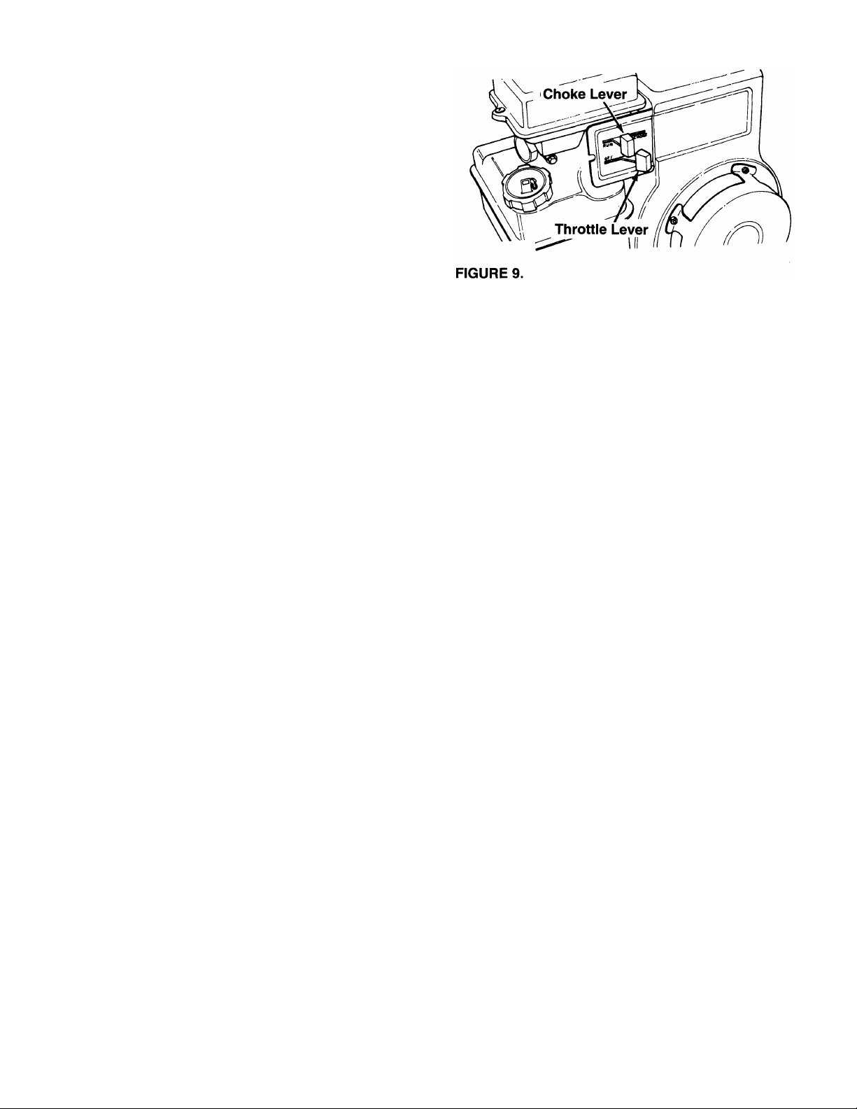
TO START ENGINE
1. Place throttle control lever on the engine in FAST
position. See figure 9.
2. Place choke lever in CHOKE position (a warm
engine may not require choking).
3. Grasp starter handle and pull rope out slowly until
engine reaches start of compression cycle (rope
will pull slightly harder at this point). Let the rope
rewind slowly.
NOTE: When restarting a warm engine, be careful to
keep away from muffler and other heated surfaces on
the engine.
4. Pull rope with a rapid, continuous, full arm stroke.
Keep a firm grip on the starter handle. Let the
rope rewind slowly. Do not let starter handle snap
back against starter.
5. Repeat preceding instructions 3 and 4 until engine
fires. When engine starts, move choke lever
halfway between CHOKE and RUN.
6. Move throttle control lever to IDLE position for a
few minutes warm-up. Gradually move choke
lever to RUN position as engine warms up.
NOTE: In order to idle smoothly, a new engine may
require 3 to 5 minutes running above slow idle speed.
Idle speed has been adjusted to be correct after this
break-in period.
7. If weather is cold, cycle the ram 6 to 8 times to
circulate the hydraulic fluid, which will warm and
thin the fluid.
TO STOP ENGINE
1. Move throttle control lever to OFF position.
2. Disconnect spark plug wire from spark plug to
prevent accidental starting while equipment is
unattended.
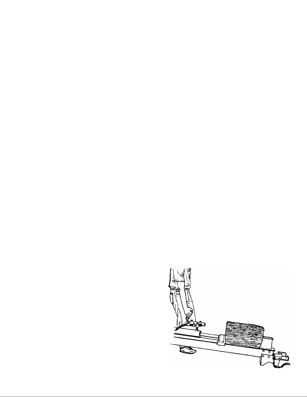
USING THE LOG SPLITTER
Use the log splitter only on a level, hard surface.
Never stand next to the ram when operating the log
splitter. Always stand behind the ram. See figure 10.
Never attempt to cut a log in half sideways. Always
split the log lengthwise. Maximum length of log to be
split is 25".
The control handle has three positions:
FORWARD (Push the control handle forward)—
Ram moves toward the splitting wedge. Control
handle will return to neutral position as soon as
hatidje is released^
NEUTRAL-(Mi^dle position)—Ram stops in place.
REVERSE (Push the control handle to the rear)—
Ram returns. The control handle will lock in the
reverse position, and will return to neutral automati
cally when the reverse stroke is complete.
TO OPERATE LOG SPLITTER:
1. Set throttle at maximum speed.
2. Place log on beam. Steady it by placing your
hand on top of the log.
3. Slowly move control handle forward until the ram
rests against the log. Release the control handle
(Neutral).
4. Remove your hand from the log and step behind
the ram. See figure 10.
5. Move control handle forward until log is split.
6. Move the control handle to the rear to return the
ram.
Page 8
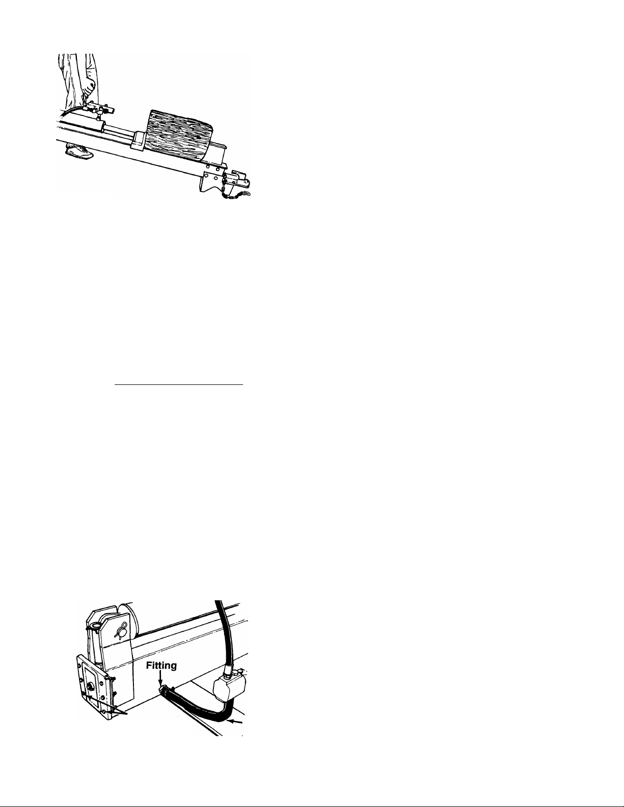
FIGURE 10.
WARNING: If the fluid becomes exces
sively hot at any time during operation,
A
TO TRANSPORT LOG SPLITTER
Attach the hitch to a towing vehicle, making certain to
latch securely. Attach the safety chains to the towing
vehicle.
stop the unit and aiiow the fiuid 1o cooi
down. Maximum performance wili not be
obtained from your log splitter if th e fiuid
is too hot. Use extreme caution as con
tacting hot fiuid could result in serious
personai injury.
MAINTENANCE
WARNING: Always stop the engine and
disconnect the spark plug wire before
A
RESERVOIR FLUID
Check the hydraulic fluid level in the log splitter reser
voir tank before each use. Refer to “Before Starting”
under Operation Section.
Change the hydraulic fluid in the reservoir evsry 100
hours of operation. Remove the six hex bolts, lock
washers and hex nuts which hold the end plat 3 to the
beam. See figure 11. Remove the plate, and drain the
fluid into a suitable container. Refill using only Dexron
II automatic transmission fluid, as instructed in the
“Initial Preparation” section of this manual, 3age 6.
Also, make certain to clean the strainer tube assembly.
FIGURE 11.
performing any maintenance or idjustments.
'Hex Bolts
Lock Washers
Hex Nuts
Suet on
Hosie
NOTE: Drain the fluid and flush the reservoir tank and
hoses with kerosene whenever any repair work is per
formed on the tank, hydraulic pump or valve.
Contaminants in the fluid will damage the hydraulic
components. (Should be performed by an authorized
service dealer.)
WARNING: Use extreme caution when
working with kerosene, as it is an
A
STRAINER TUBE ASSEMBLY
1. Loosen the hose clamp on the suction hose at
2. Using an adjustable wrench, remove the fitting
3. Reach inside the end of the beam (end plate was
4. Clean the strainer tube assembly with kerosene.
5. Reassemble the end plate. Refill reservoir tank
BEAM AND SPLITTING WEDGE
Lubricate the beam where it contacts the ram with
grease before each use to obtain years of service.
HOSE CLAMPS
Check the hose clamps on the suction hose (attached
to bottom of the pump) for proper tightness before
each use. Check the hose clamps on the return hose
(between beam and cylinder) at least once a season.
ENGINE
Refer to the separate engine manual for all engine
maintenance instructions.
Maintain engine oil as instructed in the separate
engine manual packed with your unit. Read and follow
instructions carefully.
Service air cleaner every 25 hours under normal con
ditions. Clean every few hours under extremely dusty
conditions. Poor engine performance and flooding
usually indicates that the air cleaner should be ser
viced. To service the air cleaner refer to the separate
engine manual packed with your unit.
The spark plug should be cleaned and the gap reset
once a season. Spark plug replacement is recom
mended at the start of each season; check engine
manual for correct plug type and gap specification.
Clean the engine regularly with a cloth or brush. Keep
the cooling system (blower housing area) clean to
permit proper air circulation which is essential to
engine performance and life. Be certain to remove all
dirt and combustible debris from muffler area.
extremeiy fiammable fluid.
the beam. See figure 11. Disconnect the hose
from the beam.
from the beam.
already removed), and pull out the strainer tube
assembly. See reference number 43 on page 10.
Reassemble in reverse order.
with Dexron II automatic transmission fluid as
instructed under “Initial Preparation” in Operation
Section.
Page 9

JTS a/ctt a
FLEXIBLE PUMP COUPLER
The flexible pump coupler is a nylon “spider” insert,
located between the pump and engine shaft. The
alignment is very critical. Over a period of time, the
coupler will harden and deteriorate. For a replace
ment flexible pump coupler, order part number 717-
0891.
WARNING: Never hit the pump shaft in
any manner, as any blow will cause per
A
When replacing the flexible pump coupling, proceed
as follows.
1. Place the coupling half onto the engine shaft.
2. Mount the pump onto the coupling support brack
3. Carefully slide coupling half onto pump shaft
4. Install the nylon “spider” insert into coupling half
5. Place the coupling shield in position on the hex
6. Attach the coupling support bracket to the hex
7. Adjust the two coupling halves (steel) so there is
manent damage to the pump.
Make certain there is clearance between the cou
pling half and the engine. Tighten the set screw.
et. Tighten securely.
(make certain set screw is loose). Slide the key
into place on the shaft.
on the engine shaft.
bolts. Rotate the keyway on the pump shaft so it
is toward the bottom.
bolts, carefully sliding the coupling half over the
“spider” insert. Secure coupling shield and cou
pling support bracket with lock washers and hex
nuts. Tighten securely.
between .010“ and .060" clearance between the
two halves (at least the thickness of a matchbook
cover, up to 1/16" maximum). See figure 12.
Tighten the set screw in the coupling half on the
pump shaft.
------------¡Z---------------
CARBURETOR ADJUSTMENT
WARNING: If any adjustments are made
to the engine while the engine is running
A
Minor carburetor adjustment may be required to com
pensate for differences in fuel, temperature, altitude
or load. Improper adjustment will cause stalling when
splitting is under load, hard starting and higher fuel
consumption.
Refer to the separate engine manual packed with
your log splitter for carburetor adjustment information.
NOTE: A DIRTY AIR CLEANER WILL CAUSE
ENGINE TO RUN ROUGH. BE CERTAIN AIR
CLEANER IS CLEAN AND ATTACHED TO THE
CARBURETOR BEFORE ADJUSTING CARBURE
TOR. DO NOT MAKE UNNECESSARY ADJUST
MENTS. FACTORY SETTINGS ARE SATISFACTO
RY FOR MOST APPLICATIONS AND CONDITIONS.
TIRE PRESSURE
Check sidewall of tire for manufacturer’s recommend
ed maximum tire pressure. If this information does not
appear on your tire, maximum tire pressure under any
circumstances is 30 p.s.i. Equal pressure should be
maintained on both tires.
INSTALLATION OF TIRE TO RIM
A
1.
2.
3.
(e.g. carburetor), keep clear of all moving
parts. Be carefui of heated surfaces and
muffler.
WARNING: The following procedure must
be followed when removing or installing
a tire to the rim.
Be certain rim is clean and free of rust.
Lubricate both the tire and rim generously.
Never inflate to over 30 p.s.i. to seat beads.
Excessive pressure when seating beads may
cause tire/rim assembly to burst with force suffi
cient to cause serious injury.
NOTE: Make certain proper clearance is obtained
before tightening set screw.
PUMP
OFF-SEASON STORAGE
If the log splitter will not be used for a period longer
than 30 days, the following steps should be taken to
prepare the log splitter for storage.
1. Clean the engine and the entire log splitter
thoroughly.
2. Refer to the engine manual for correct engine stor
age instructions. Follow instructions carefuily.
3. Wipe unit with an oiled rag to prevent rust, espe
cially wedge and beam.
4. Store unit in a clean, dry area. Do not store next
to corrosive materials, such as fertilizer.
NOTE: When storing any type of power equipment in
an unventilated or metal storage shed, care should be
taken to rustproof the equipment by coating with a
light oil or silicone.
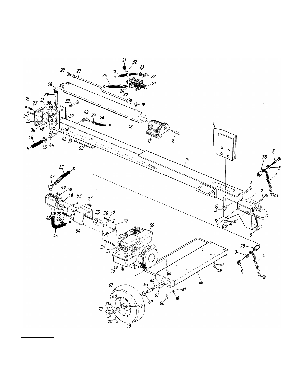
Page 10
Model 610
0\L. C^PftC^TУ
J gallons 'bOCR.OhJ JL
AuTornKnc "TfetoSMissiat^
fLUm
15
iJ /11 LoL LeMeii
10
Page 11

Model 610
PARTS LIST FOR MODEL 610 LOG SPLITTER
REF.
NO.
10
11
12
13 712-0337
14
15
16 738-0601 Shid. Bolt .62" Dia. x .475" 57
17 719-0269B
18
19
20 737-0192 90° Solid Male Adapter
21
22
23
24 737-01^1
25
! 26
27
28 745-0174 Cap 71
29 781-0036
30 721-0204
31 720-0231 Ball Knob 74 714-0162
32
33
34
35
36
37
38
39
40 736-0275
1
2
PART
NO.
781-0038
710-0693
CODE DESCRIPTION
Wedge Ass’yHex Bolt 3/8-16x4.5" Lg. 42
(Gr. 5)
REF.
NO.
41
43
3 736-0262 FI-Wash. .375" I.D. x .87" O.D. 44
4
713-0433
6
710-0298
7
710-3130 Hex Bolt 3/8-16x3.25" Lg.
8
727-0289
9 750-0261
736-0169
712-3000
781-0311
Chain—Tow Hitch
Hex Bolt 5/8-18x3.5" Lg.
(Gr. 8)
Tow Hitch Ass’y■
Spacer .375" I.D. x .625" O.D.
L-Wash. 3/8" I.D.*
Hex Cent. L-Nut 3/8-16 Thd.
Beam Stand
45
46 727-0429 Suction Hose 1" I.D.
47
48 717-0936
49 712-0123 Hex Nut 5/16-24 Thd.*
50 736-0119 L-Wash. 5/16" I.D.*
51 714-0122
52 781-0097
53
Hex Nut 5/8-18 Thd.* 54 719-0278
736-0158
781-0343
717-1346
737-0238
452
638 Hydraulic Cylinder
L-Wash. 5/8" I.D.*
Oil Tank Ass’y.
Pusher Plate
Pipe Nipple 1/2" NPTx2" Lg.
55
56
58 710-0363
59
60 710-0409
61
717-1347 Control Valve 62 710-0152
737-0153
726-0146
727-0430 HighTPressure Hydraulic Hose
Return Elbow
Adjustable Hose Clamp
90° Solid Male Adapter
63 750-0442
64
66
67
29.5" Lg. 734-0872
727-0435
727-0307 Metal Pressure Tube
747-0709
710-1036
Return Hose 3/4" I.D. x 231/2"
Lg.
68 734-0255 Air Valve
69 721-0168
70
Filler Tube Ass’y.
“0”-Ring .92" I.D.
Control Handle
72 712-0299
73
75
Hex Bolt 3/4-10x4.5" Lg. 76 710-0604
710-0442 Hex Bolt 5/16-18 X 1.5" Lg.*
781-0361
Beam End Plate 77
721-0203A Gasket
712-0203
736-0364
712-0338
Hex Nut 3/4-10 Thd.* 78 750-0497
L-Wash. 3/4" I.D.*
Hex Nut 1-1/16-12 Thd.
79 741-3029 N
80
FI-Wash. .34" I.D. x .68" O.D.
PART
NO.
712-0158 Hex L-Nut 5/16-18 Thd.
737-0259 90° Adapter 3/4" Hose
781-0021
737-0191
726-0132
737-0265 90° Adapter
710-0117
717-0891
710-0237
781-0098
—
712-0241
781-0018
781-0033B
734-1016 Wheel Ass’y. Comp.
734-1017
741-3028 N
734-0873 Hub Cap
714-3024
721-0205
712-3017
CODE
DESCRIPTION
Strainer Tube Ass’y.
Adapter 1"x 1-1/16-12 Thd.
Hose Clamp 5/8"
Two Volume Pump (Incl. Ref. 75)
Sq. Key 3/16 X .75" Lg.
Rear Coupling Support Bracket
Hex Bolt 5/16-24 X 1.0" Lg.*
Coupling Shield
Flexible Coupling
Hex Bolt 5/16-24 X .62" Lg.
Front Coupling Support Bracket
Hex Bolt 5/16-24x4.0" Lg.
Engine
Hex Bolt 5/16-24 X 1.75" Lg.*
Hex Nut 3/8-24 Thd.*
Hex Bolt 3/8-24 x 1.0" Lg.*
Spacer .75" I.D. x 1.12" O.D.
Axle Assembly
Engine Frame Ass’y.
Tire Only
Bearing Seal
Rim Only
Bearing Cone
Hex Slotted Nut 3/4-16 Thd.
Cotter Pin 5/32" Dia.
Hi-Pro Key 1/8" X 1/2" Lg.
Hex TT-Tap Scr. 5/16-18 x .62"
Lg.
Gasket Washer 5/16" I.D. x
3/4" O.D.
Spacer .375" I.D. x .625" O.D.
Bearing Cup
Hex Nut 3/8-16 Thd. (Gr. 5)
*For faster service obtain standard nuts, bolts and washers localiy.
If these items cannot be obtained locally, order by part number
and size as shown on parts list.
NOTE
Specifications subject to change without notice or
obligation.
11
NOTE: The engine is not under warranty by the
log splitter manufacturer. . .If repairs or service
is needed on the engine, piease contact your
nearest authorized engine —
service outlet. Check the Find It Fast
“Yellow Pages” of your in The
telephone book under Yellow Pages
“Engines-Gasoline.”
------------
Page 12

TROUBLE SHOOTING GUIDE
Trouble Possible Caus3(s)
Engine fails to start
Engine runs erratic
Engine overheats
1. Fuel tank empty, or stale fuel.
2. Blocked fuel line.
3. Spark plug v^ire disconnected.
4. Faulty spark plug.
1. Unit running on CHOKE.
2. Spark plug v/ire loose.
3. Blocked fuel line or stale fuel.
4. Water or din in fuel system.
5. Dirty air dee ner.
6. Carburetor c ut of adjustment.
1. Engine oil level low.
2. Air flow rest icted.
3. Carburetor not adjusted properly.
Corrective Action
1. Fill tank with clean, fresh gasoline.
2. Clean fuel line.
3. Connect wire to spark plug.
4. Clean, adjust gap or replace.
1. Move choke lever to OFF position.
2. Connect and tighten spark plug
wire.
3. Clean fuel line; fill tank with clean
fresh gasoline.
4. Drain fuel tank. Refill with fresh
fuel.
5. Clean air cleaner as instructed in
separate engine manual.
6. Adjust carburetor (see Carburetor
Adjustment in separate engine
manual).
1. Fill crankcase with proper oil.
2. Remove blower housing and
ciean as instructed in
separate engine manual.
3. Adjust carburetor (see Carburetor
Adjustment in separate engine
manual).
Will not split logs
Leaking cylinder
NOTE: For repairs beyond the minor adjus tments listed above, piease contact your nearest authorized service deaier.
*Shouid be performed by an authorized s€ rvice dealer only.
Reservoir fluid level low.
1. Broken seals.
2. Scored cylir der.
Check and fill reservoir tank as
instructed in Operation section
of this manual.
1. Replace seals.*
2. Replace cylinder.*.
FOR REPLACEMENT PARTS, CONTACT:
SERVICE DEPARTMENT • P.O. BOX 360900 • CLEVELAND, OHIO 44136
 Loading...