

Page 1
OIWNER’S
MANUAL
EDGER
.75
Model Numbers
242-595A
24596-A
Important:
Read Safety Rules and
Instructions Carefully
Thank you for purchasing an
American built product.
PRINTED IN U.S.A.
FORM NO. 770-1803
Page 2

INDEX
Safe Operation Practices
Assembly Instructions
Operation
Adjustments
Lubrication
......................................................................
.................................................................
....................................................................
...................................................
♦
♦
♦
♦
♦
For one year from the date of original retail purchase, MTD PRODUCTS INC will either
repair or replace, at its option, free of charge, F.O.B. factory or authorized service firm, any
part or parts found to be defective in material or workmanship. Transportation charges for
the movement of any power equipment unit or attachment are the responsibility of the pur
chaser. Transportation charges for any parts submitted for replacement under this warran
ty must be paid by the purchaser unless such return is requested by MTD PRODUCTS INC.
♦
♦
♦
♦
This warranty will not apply to any part which has become inoperative due to misuse, ex
cessive use, accident, neglect, improper maintenance, alterations, or unless the unit has
been operated and maintained in accordance with the instructions furnished. This warran
ty does not apply to the engine, motor, battery, battery chargeror component parts thereof.
Please refer to the applicable manufacturer’s warranty on these items.
..............................................
LIMITED WARRANTY
3
4
7
7
8
Maintenance................................................................. 8
Off-Season Storage
Illustrated Parts............................................................
Parts List
......................................................................
....................................................
♦
♦
♦
♦
♦
♦
♦
t
1 I
♦
♦
♦
♦
This warranty will not apply where the unit has been used commercially.
Warranty service is available through your local authorized service dealer or distributor. If
you do not know the dealer or distributor in your area, please write to the Customer Service
Department of MTD.
The return of a complete unit will not be accepted by the factory unless prior written per
mission has been extended by MTD.
♦
This warranty gives you specific legal rights. You may also have other rights which vary
from state to state.
J
WARNING
(D
TO PURCHASERS
OF INTERNAL COMBUSTION ENGINE EQUIPPED
MACHINERY OR DEVICES IN THE STATE OF CALIFORNIA
The equipment which you have just purchased does not have a spark arrester. If this equipment is used on
any forest covered land, brush covered land, or grass covered unimproved land in the State of California,
before using on such land, the California law requires that a spark arrester be provided. In addition, spark
arrester is required by law to be in effective working order. The spark arrester must be attached to the
exhaust system and comply with Section 4442 of the California Public Resources Code.
♦
♦
♦
♦
♦
♦
Page 3

IMPORTANT
It is suggested that this manual be read in its entirety before attempting to assemble or operate. Keep this
j|g g ^g^^ p|ac6 for futurB referencB and for ordering replacement parts.
This unit is shipped WITHOUT GASOLINE or OIL. After assembly, see operating section of this manual for
proper fuel and engine oil recommendations.
SAFE OPERATION PRACTICES FOR EDGERS
TRAINING
1. Read this Operating and Service Instruction
Manual carefully. Be thoroughly familiar with the
controls and the proper use of the equipment.
2. Never allow children to operate a power edger.
3. Keep the area of operation clear of all persons,
particularly small children and pets.
PREPARATION
Thoroughly inspect the area where the equipment
is to be used and remove all stones, sticks, wire,
bones and other foreign objects.
2. Do not operate equipment when barefoot or
wearing open sandals. Always wear substantial
footwear.
3. Check the fuel before starting the engine. Do
not fill the gasoline tank indoors, when the
engine is running, or while the engine is still hot.
Wipe off any spilled gasoline before starting the
engine.
4. Disengage the blade clutch on units so equipped
before starting the engine.
5. Never attempt to make a wheel adjustment
while the engine is running.
6. Never operate the equipment in wet grass. Always
be sure of your footing; keep a firm hold on the
handle and walk, never run.
OPERATION
Do not change the engine governor settings or
overspeed the engine.
2. Do not put hands or feet near or under rotating
parts. Keep clear of the discharge opening at
all times.
3. Stop the blades(s) when crossing gravel drive,
walks or roads.
4. After striking a foreign object, stop the engine,
remove the wire from the spark plug, thoroughly
inspect the edger for any damage, and repair the
damage before restarting and operating the edger.
5. If the equipment should start to vibrate abnor
mally, stop the engine and check immediately
for the cause. Vibration is generally a warning
of trouble.
6. Stop the engine whenever you leave the equip
ment, before cleaning the guard assembly, and
when making any repairs or inspections.
7. When cleaning, repairing or inspecting, make
certain the blade and all moving parts have
stopped. Disconnect the spark plug wire, and
keep the wire away from the plug to prevent
accidental starting.
8. Do not run the engine indoors.
9. Shut the engine off and wait until the blade
comes to a complete stop before unclogging
guard assembly.
MAINTENANCE AND STORAGE
1. Check the blade and engine mounting bolts at
frequent intervals for proper tightness.
2. Keep all nuts, bolts, and screws tight to be sure
the equipment is in safe working condition.
3. Never store the equipment with gasoline in the
tank inside of a building where fumes may
reach an open flame or spark. Allow the engine
to cool before storing in any enclosure.
4. To reduce fire hazard, keep the engine free of
grass, leaves, or excessive grease.
Page 4
A
---
►
mämttmm
B—*
c—* c
n—► *"
FIGURE 1
ASSEMBLY
TOOLS REQUIRED
;
-im
F-
f-
r*w
%
ft
G-
(1) Adjustable wrench or 3/4" open end or bov^
wrench
(2) 7/16" open end or box wrench
(1) 9/16" open end or box wrench
■CONTENTS OF HARDWARE PACK
(See figure 1)
A
(3)
Shoulder Bolts 3/8-16 Thread
B
(3)
Belleville Washers
C
(3) Lock Washers
D
(3) Hex Nuts 3/8-16 Thread
E
(2) Hex Bolts 1/4-20 x 1 1/4" Long
F
G (6)
H
1
J
Lock Washers 1/4" I.D.
(6)
Hex Nuts 1/4-20 Thread
Compression Spring
(1)
(4) Carriage Bolts 1/4-20 x 1 1/4" Long
(2) Cotter Pins
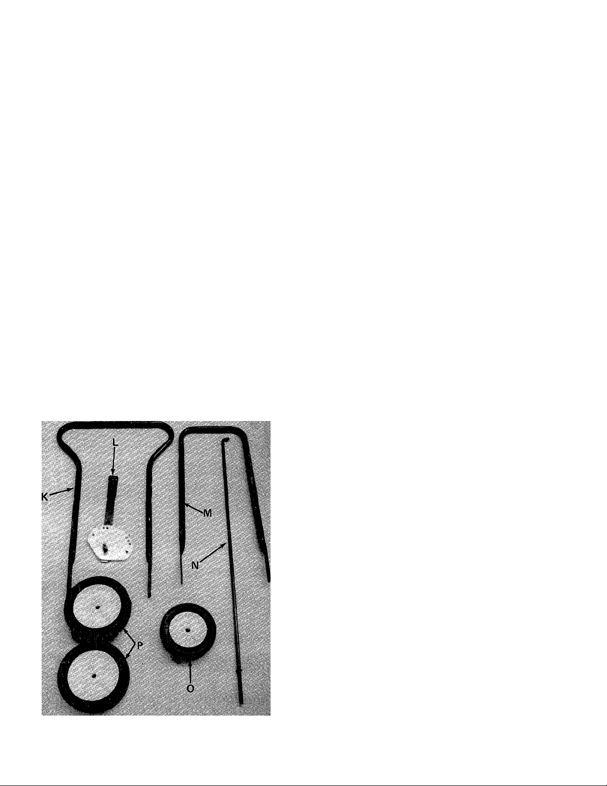
FIGURE 2
LOOSE PARTS IN CARTON
(See figure 2)
K
L
M
N
0
P
Your new edger is shipped preassembled with the^
exception of the handle, rear wheels and front whr
1. Remove the edger and all parts from the cartoti.
Make certain that all loose parts and literature
are removed from carton before carton is discarded.
Upper Handle
(1)
Preassembled Clutch 1
(1)
Lower Handle
(1)
Clutch Rod
(1)
Front Wheel 6"
(1)
Rear Wheels 7"
(2)
Dia.
Dia.
Page 5

SHOULDER
BOLT (A)
BELLEVILLE
WASHER (B)
FIGURES.
SHOULDER
BOLT (A)
FRONT
WHEEL (O)
LOCK WASH
Place lower handle into the slots in the rear
frame. See figure 3.
Line up holes in handle with holes in frame.
See figure 3.
Secure rear wheels (P) and lower handle (M) to
frame with shoulder bolts (A), belleville washers
(B), lock washers (C) and hex nuts (D). See
figure 3.
Assemble the front wheel (O) as shown in figure
4. Place shoulder bolt (A) through wheel, then
belleville washer (B) (between wheel and frame).
Secure with lock washer (C) and hex nut (D).
See figure 4.
.BELLEVILLE;
WASHER (B)
FIGURE 4.
LOWER
HANDLE
FIGURE 5.
Assemble the upper handle (K) to lower handle.
Place the head of carriage bolts (I) to the outside
of handle. Secure with lock washers (F) and
and hex nuts (G). See figure 5.
Page 6

LEFT HAND
SIDE OF UPPER
HANDLE
PREASSENIBLED
CLUTCH PLATE
ASSEMBLY (L)
NOTE
Right and left hand side is determined
from behind the edger, in the opera
tor's position.
L’OCK WASHER (F),
HEX NUT (G)
FIGURE 6.
HEX BOLT (E)
CLUTCH ROD (N)
7. Place preassembled clutch plate assembly (L)
on the left hand side of upper handle. Secure
in place with hex bolts (E), lock washers (F)
and hex nuts (G). See figure 6.
8. Place compression spring (H) over straight end
of clutch rdd (N). Place end of rod in spindle
bracket assembly and secure with cotter pin (J),See figure 7.
FIGURE?.
FIGURES.
COTTER
PIN U)
V’V.
9. Place hook end of clutch rod (N) in clutch
lever. Secure with cotter pin (J). See figure 8.
CLUTCH
LEVER
CLUTCH
ROD (N)
Page 7

OPERATION
1. Fill the crankcase with oil using a high quality
detergent oil classified "For Service MS". Use
SAE 30 oil. Nothing should be added to the
recommended oil.
Place the engine level. Remove oil fill cap. FILL
THE OIL SUMP TO POINT OF OVERFLOW. Pour
slowly. See figure 9.
.CAUTION
A
The manufacturer recommends that
the operator wear safety glasses or
some other suitable eye protection.
To stop the edger engine, push the grounding clip
against the spark plug. See figure 11.
FIGURE 9.
2. Fill the gasoline tank with "regular" gasoline.
3. Pull the choke control out to "choke" position
if necessary. See figure 10.
PULL OUT TO CHOKE
FIGURE 11.
Depth Control Adjustment - The clutching and
declutching of the belt is accomplished by moving
the clutch lever. To declutch, pull the clutch lever
towards you as you operate the edger. The farther
you push the clutch lever forward, the deeper the
cut.
ADJUSTMENTS
WARNING
i
Disconnect the spark plug wire and
ground against the engine before per
forming any adjustments, repairs or
maintenance.
t
FIGURE 10.
4. Grasp the starter handle and pull out the cord
rapidly. Return it slowly to the engine.
5. After engine starts, push choke control in grad
ually.
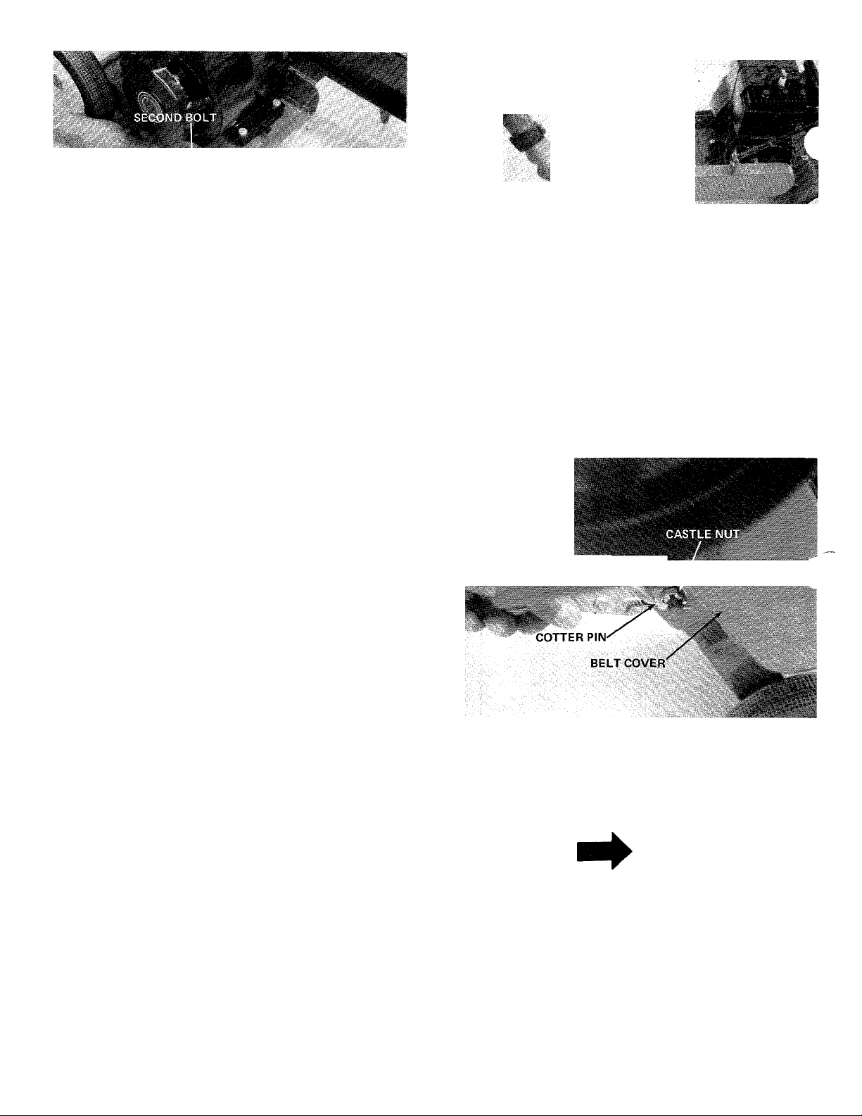
Front Wheel Adjustment
The front wheel may be raised or lowered to give
added cutting depth.
Loosen the second bolt on the front wheel support
bracket. Pivot the bracket up or down to desired
height. Retighten bolt. See figure 12.
Page 8
WHEEL SUPPORT^
BRACKET
SPIIMDLJE
BOLT
SPINDLE NUT
FIGURE 12.
LUBRICATION
Engine - Refer to separate engine manual for lubrica
tion instructions.
Wheels - The wheels require no lubrication.
Spindle Bearing - The ball bearing in the spindle is
lubricated and sealed at the factory and requires no
lubrication. Lubricate all other moving parts with
engine oil.
MAINTENANCE
i WARNING j
(D
Disconnect the spark plug wire and
ground against the engine before per
forming any adjustments, repairs or
maintenance.
FIGURE 13.
Belt Removal - Remove the spark plug wire and
ground. Remove the gasoline.
1. Tip the edger back so that it rests on the handle.
2. Remove the cotter pin securing the castle nut
on the bottom of belt cover. See figure 14.
FIGURE 14.
3. Lift off the hex castle nut, belleville washer and
belt cover. See figure 15.
4. Remove the old belt and replace with new belt.
Blade Removal - Hold head of spindle bolt with
a 3/4" or adjustable wrench and remove spindle nut.
See figure 13.
Engine Oil - Check oil level before starting engine
and after every 5 hours of operation. Add oil as
necessary to keep level full to point of overflowing.
Before removing plug, clean area around plug to pre
vent dirt from entering oil fill opening.
Change oil after first 5 hours of operation. There
after, change every 25 hours. Change oil while engine
is warm. Oil may be drained thru oil drain plug.
See figure 9. Crankcase capacity - 1 1/4 pints.
NOTE
While the belt cover is removed, it is
a good idea to apply a little grease to
the pivot point on belt cover. See
figure 15.
5. Reassemble the belt cover, making sure the new
belt is over the engine pulley.
6. When tightening the castle nut, only tightt,
enough to line up hole in bolt for cotter pin. DO
NOT OVER TIGHTEN. Belt cover must pivot
freely. See figure 15.
Page 9

MOUNTING
BOLT
COTTER PIN
CASTLE NUT
BELLEVILLE
WASHER
FIGURE 15.
Set edger back on its wheels. Replace spark plug
wire.
OFF-SEASON STORAGE
The following steps should be taken to prepare unit
for storage.
1. Clean and lubricate unit thoroughly.
2. Refer to engine manual for correct engine storage
instructions.
3. Coat unit's cutting blade with chassis grease to
prevent rusting.
4. Store unit in a dry, clean area.
Page 10
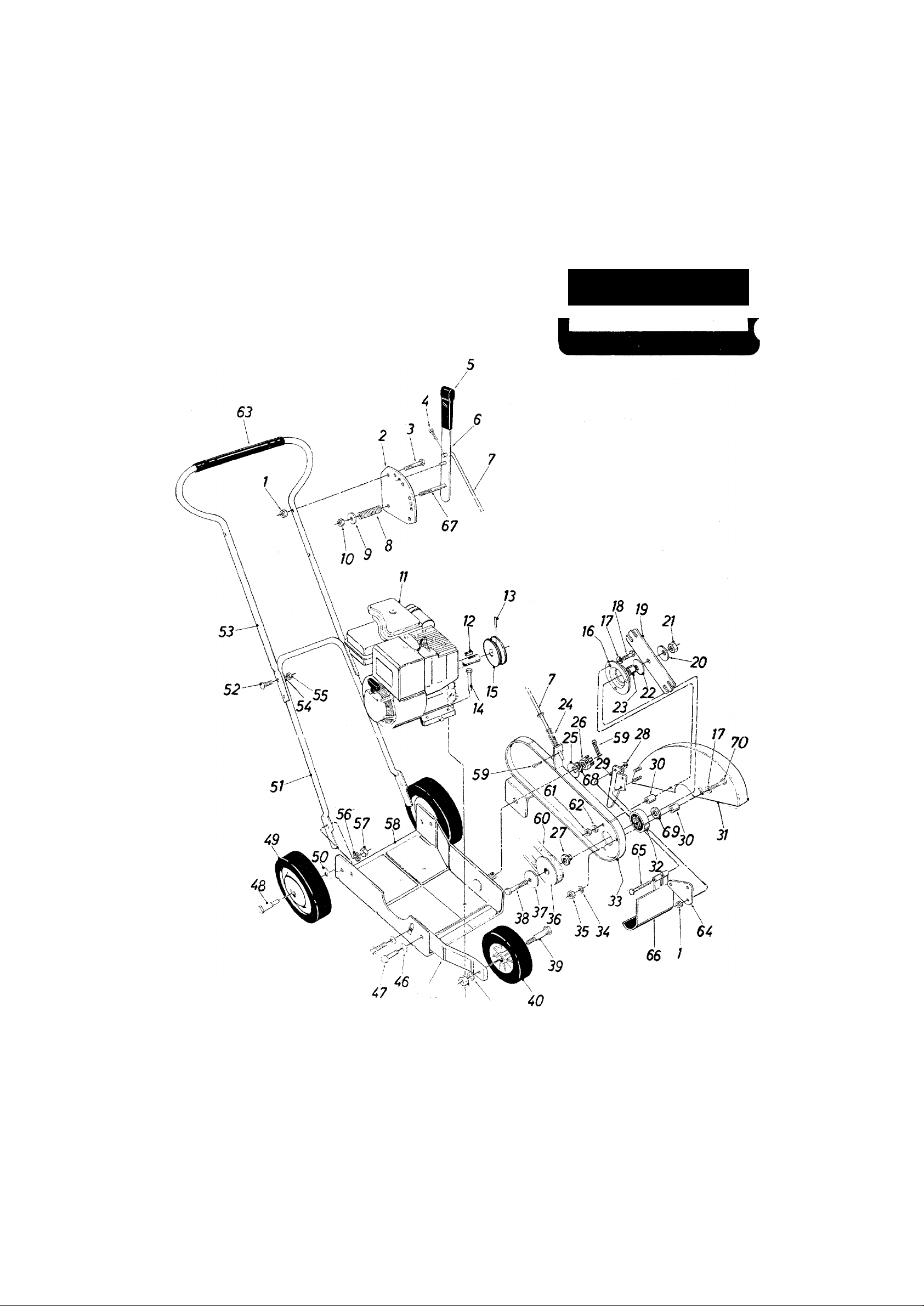
Models 595 and 596
IF YOU WRITE TO US ABOUT THIS ARTICLE
OR IF YOU ORDER REPLACEMENT PARTS Al
WAYS MENTION THIS MODEL & SERIAL NO
MODEL
45
43 f44
¿2 41
10
Page 11

Models 595 and 596
PARTS LIST FOR MODELS 595 and 596 EDGERS
Part
Color
No.
Code
1
712-0107
2
09950 Clutch Plate
3
710-0106
4
714-0115
Hex Cent. L.-Nut 1/4-20 Thd.
Hex Bolt 1/4-20 x 1.25" Lg.*
Cotter Pin 1/8" Dia. x 1.0"
DESCRIPTION
Lg.*
5
720-0142 Grip
6
7
09948
747-0358
Clutch Handle Ass'yClutch Rod
8 732-0171 Compression Spring .50"
O.D. X 1.40" Lg.
9 736-0264
Fl.-Wash. .33" I.D. x .63"
O.D. X .063
10
712-0158
11
12
714-0105 Sq.Key 3/16 X 3/16 X 1.0"
Hex Cent. L.-Nut 5/16-18 Thd.
Engine
Lg.*
13
710-0938 Set Sc r. 1/4-28 x 1/4" Lg.
14
710-0442 Hex Bolt 5/16-18 X 1.50'^' Lg.*
15 711-0421
Engine Pulley 49 734-0480
16 08253 Bearing Housing
17
736-0242 Bell.-Wash. .34" I.D. x 88"
O.D. X .060
18
710-0528 Hex Bolt 5/16-18 X 1.25" Lg.*
19 09954
20
736-0112 Bell.-Wash. .535" I.D. x 1.50"
Blade
O.D. X .052 53 749-0’
712-0239 Hex Cent. L.-Nut 1/2-20 Thd.
-2
736-0112 Bell.-Wash. .535" I.D. x 1.50" 55
O.D. X.052
23 748-0190 Spacer .513" I.D. x .703"
O.D. X .69" Lg. 58 13330 -497
24
732-0330
Compression Spring .57"
O.D. X 1.92" Lg.
25 736-0112 Bell.-Wash. .535" I.D. x 60
1.50" O.D. X .052
712-0114
26
27 711-0716
726-0111 Push Cap
28
09952
29
30 748-0298
Hex Castle Nut 1/2-20 Thd. 62
Shoulder Spacer 63
Guide 65
Spacer .354" I.D. x .635"
O.D. X .510" Lg.
14341
31
32 741-0919
- 497 Blade Guard
Ball Bearing .787" I.D.
x4.85" O.D. X .551 X .090
13333 - 497
33
34 736-0119
712-0267
35
756-0361 Pulley
36
Spindle Bracket Ass'y-
L-Wash. 5/16" I.D.*
Hex Nut 5/16-18 Thd.
Ref.
New
Part
No.
37
38
39
40
41
42
43
44
45
46
47 710-0623
48 738-0213
50 736-0105
51
52 710-0111
54
56 736-0169
57
59
61
64 14427
66
67
68
69
70
Part
Color
No.
Code
736-0112
710-0515
738-0213
734-0481
736-0169
712-0267
736-0119
712-0798
13332
736-0105
749-0455-
736-0329
712-0287
712-0798
714-0115
754-0142
712-0267
736-0119
718-0144
711-0720
731-0532
710-0380
736-0192
736-0272
710-0116
DESCRIPTION
Bell.-Wash. .535" I.D. x 1.50"
O.D. x .052
Hex Bolt 1/2-20x3.50" Lg.*
Shoulder Bolt .498" Dia. x
1.450
Wheel Ass'y. Comp. 6" Dia.
X 1.50
L-Wash. 3/8" I.D.*
Hex Nut 5/16-18 Thd.*
L-Wash. 5/16" I.D.*
Hex Nut 3/8-16 Thd.*
Front Wheel Support
Bell.-Wash. .400" I.D. x 88"
O.D.
Hex Wash. Hd. Self Tap Scr.
3/8-16 X .75" Lg.
Shoulder Bolt .498" Dia. x
1.450
Wheel Ass'y. Comp. 7" Dia.
X 1.50
Bell.-Wash. .400" I.D. x 88"
O.D.
Lower Handle
Carriage Bolt 1/4-20 x 1.25"
Lg.*
Upper Handle
L-Wash. 1/4" I.D. *
Hex Nut 1/4-20 Thd.*
L-Wash. 3/8" I.D.*
Hex Nut 3/8-16 Thd.*
Base Ass'y.
Cotter Pin 1/8" Dia. x 1.0"
Lg.*
3V-Belt31.2" Lg.
Hex Nut 5/16-18 Thd.*
L-Wash. 5/16" I.D.*
Grip (Optional)
Flap Bracket
Hinge Pin
Debris Deflector
Hex Bolt 5/16-18 X 1.75"
Lg.*
Fl.-Wash. .53 I.D. x.93 O.D.
Fl.-Wash. .51 I.D. x 1.00
O.D. X.060
Hex Bolt 5/16-18 X 2.00"
Lg.*
New
Part
*For faster service obtain standard nuts, bolts and washers locally. If these items cannot be obtained locally, order by part number and
size as shown or parts list.
The engine is not under warranty by the edger manufacturer. If repairs or service is needed on the
engine, please contact your nearest authorized engine service outlet. Check the “Yellow Pages” of
your telephone book under “Engines — Gasoline.”
Find It Fast
In The
Yellow Pages
11
Page 12

MTD PRODUCTS INC
YaRD-MaN COMPANY
P.O. BOX 36900 • CLEVELAND OHIO 44136
 Loading...