

Page 1

.50
ASSEMBLY
OPERATION
MAINTENANCE
PARTS LIST
IMPORTANT:
Read Safety Rules
and Instructions
PRINTED IN U.S.A.
MODEL NUMBERS
240-670A
240-680A
POWER
VACUUMS
FORM NO. 770-0091
Page 2

INDEX
Safe Operation Practices......................................— 3
Assembly Instructions............................................... 4
Operation Instructions............................................... 5
Adjustments.................................................................5
r
♦
♦
♦
♦
♦
♦
♦
♦
♦
♦
♦
♦
For one year from the date of original retail purchase, MTD PRODUCTS INC will either
repair or replace, at Its option, free of charge, F.O.B. factory or authorized service firm,
any part or parts found to be defective in material or workmanship. Transportation charges
for any parts submitted for replacement under this warranty must be paid by the purchaser
unless such return is requested by MTD PRODUCTS INC.
This warranty will not apply to any part which has become inoperative due to misuse,
excessive use, accident, neglect, improper maintenance, alterations, or unless the unit
has been operated and maintained in accordance with the instructions furnished. This
warranty does not apply to the engine, motor, battery, battery charger or component parts
thereof. Please refer to the applicable manufacturer’s warranty on these items.
This warranty will not apply where the unit has been used commercially.
Warranty service is available through your local authorized service dealer or distributor. If
you do not know the dealer or distributor in your area, please write to the Customer Service
Department of MTD.
LIMITED WARRANTY
Exploded Views
Repair Parts List...........................................7, 9,11,12
Parts Information........................................Back Cover
.................................. ........
6, 8,10,12
♦
♦
♦
♦
♦
♦
♦
♦
♦
♦
♦
♦
♦
♦
♦
♦
♦
The equipment which you have just purchased does not have a spark arrester. If this equipment is used on
any forest covered land, brush covered land, or grass covered unimproved land in the State of California,
before using on such land, the California law requires that a spark arrester be provided. In addition, spark
arrester is required by iaw to be in effective working order. The spark arrester must be attached to the
exhaust system and comply with Section 4442 of the California Public Resources Code.
The return of a complete unit will not be accepted by the factory unless prior written
permission has been extended by MTD.
This warrany gives you specific legal rights. You may also have other rights which vary
from state to state.
WARNING TO PURCHASERS
OF INTERNAL COMBUSTION ENGINE EQUIPPED
MACHINERY OR DEVICES IN THE STATE OF CALIFORNIA
♦
♦
♦
♦
Page 3

IMPORTANT
It is suggested that this manual be read in its entirety before attempting to assemble or operate. Keep this
manual in a safe place for future reference and for ordering replacement parts.
This unit is shipped WITHOUT GASOLINE or OIL. After assembly, see operating section of this manual for
proper fuel and amount.
SAFE OPERATION PRACTICES FOR POWER VACUUMS
1. Read the operating and service instructing
manual carefully. Be thoroughly familiar with
the controls and proper use of the power
vacuum.
2. Never allow children to operate this power
vacuum.
3. Keep the area of operation clear of all per
sons, particularly small children and pets.
4. Check fuel before starting engine. Do not fill
fuel tank indoors, when engine is running, or
while engine is hot. Wipe off any spilled fuel
before starting engine.
5. Do not change engine governor settings.
6. Do not put hands near rotating parts for
any reason.
7. If the power vacuum should start to vibrate
abnormally, stop the engine and check
immediately for the cause. Vibration is
generally a warning of trouble.
8. Before cleaning, repairing or inspecting make
certain all moving parts have come to a
complete stop. Disconnect spark plug wire
and keep wire away from plug to prevent
accidental starting. Also keep throttle control
lever in the stop position.
9. If the power vacuum should become blocked
with debris at any point shut engine off and
wait until the impeller comes to a complete
stop before attempting to remove the
obstruction. Disconnect spark plug wire to
prevent accidental starting.
10. Check all bolts for tightness at frequent
periods.
11,
Never store this power vacuum with fuel in the
tank. Allow engine to cool before starting in
any enclosure.
12.
Keep bag and equipment free of debris when
not in use.
13.
Never operate this power vacuum unless air
duct and vacuum bag are properly affixed
in their place. Large zippered end of bag must
be closed when operating to prevent objects
from being blown out.
14.
Never empty vacuum bag when engine is
running.
15. Never change inlet nozzle or auxiliary hose
attachment when engine is running.
16. The manufacturer recommends that the
operator wear safety glasses or some other
suitable eye protection when operating this
machine.
17. Check the vacuum bag frequently for wear and
replace when necessary.
Page 4
ASSEMBLY
INSTRUCTIONS
(Refer to figures 1, 2 and 3)
1. Place the upper handle in position and fasten
with four (4) hex screws and hex centerlock
nuts provided.
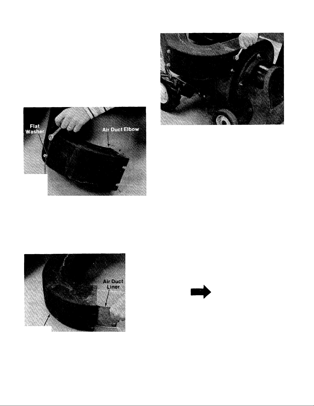
2. Place the air duct liner (studded end first) into
the elbow of air duct. See figure 1.
Hex Nut
FIGURE 1.
3. Insert studs of air duct liner through holes in
air duct. Thread on two (2) flat washers and
hex nuts (provided) several turns—do not
tighten. See figure 2.
FIGURE 3.
5. Secure the two (2) hex nuts onto the air duct
liner studs at the air duct elbow.
6. Slide the vacuum bag over the back of the
upper handle and snap the four flaps to hold
the bag.
7. Fasten the deflector on the top of the air duct
with three hex screws, flat washers and hex
nuts. (See figure 1.)
8. Slide the bag over the air duct.
9. Fasten the nozzle to the front of the vacuum
with four flat washers and thumb nuts
provided.
10. Use the following steps on the self propelled
unit only.
11. Fasten the throttle control to the right hand
side of the upper handle with one hex screw
and hex center locknut provided.
12. Secure throttle control cable to the lower
handle with the cable clip provided.
Air Duct
FIGURE 2.
4. Place the air duct in position on the blower
housing and fasten with four (4) flat washers
and hex nuts provided. See figure 3.
\
NOTE
Cable clip must be assembled to
lower handle with the open end
towards the engine. This will pre
vent wear to the bag.
13. Place ferrule through control lever.
14. Place flat washer over ferrule and thread
control rod into ferrule about eight or nine
turns.
15. Hook formed end of control rod in the shifting
finger.
16. Place curved face of spacer towards the
outside of upper handle ieh hand side.
Page 5

IMPORTANT
It is suggested that this manual be read in its entirety before attempting to assemble or operate. Keep this
manuai in a safe place for future reference and for ordering replacement parts.
This unit is shipped WITHOUT GASOLINE or OIL. After assembly, see operating section of this manual for
proper fuel and amount.
SAFE OPERATION PRACTICES FOR POWER VACUUMS
1. Read the operating and service instructing
manuai carefuily. Be thoroughiy familiar with
the controls and proper use of the power
vacuum.
2. Never allow children to operate this power
vacuum.
3. Keep the area of operation clear of all per
sons, particularly small children and pets.
4. Check fuel before starting engine. Do not fill
fuel tank indoors, when engine is running, or
while engine is hot. Wipe off any spilled fuel
before starting engine.
5. Do not change engine governor settings.
6. Do not put hands near rotating parts for
any reason.
7. If the power vacuum should start to vibrate
abnormally, stop the engine and check
immediately for the cause. Vibration is
generally a warning of trouble.
8. Before cleaning, repairing or inspecting make
certain all moving parts have come to a
complete stop. Disconnect spark plug wire
and keep wire away from plug to prevent
accidental starting. Also keep throttle control
lever in the stop position.
9. If the power vacuum should become blocked
with debris at any point shut engine off and
wait until the impeller comes to a complete
stop before attempting to remove the
obstruction. Disconnect spark plug wire to
prevent accidental starting.
10. Check all bolts for tightness at frequent
periods.
11. Never store this power vacuum with fuel in the
tank. Allow engine to cool before starting in
any enclosure.
12. Keep bag and equipment free of debris when
not in use.
13. Never operate this power vacuum unless air
duct and vacuum bag are properly affixed
in their place. Large zippered end of bag must
be closed when operating to prevent objects
from being blown out.
14. Never empty vacuum bag when engine is
running.
15. Never change inlet nozzle or auxiliary hose
attachment when engine is running.
16. The manufacturer recommends that the
operator wear safety glasses or some other
suitable eye protection when operating this
machine.
17. Check the vacuum bag frequently for wear and
replace when necessary.
Page 6

ASSEMBLY
INSTRUCTIONS
(Refer to figures 1, 2 and 3)
1. Place the upper handle in position and fasten
with four (4) hex screws and hex centerlock
nuts provided.
2. Place the air duct liner (studded end first) into
the elbow of air duct. See figure 1.
Hex Nut
FIGURE 1.
3. Insert studs of air duct liner through holes in
air duct. Thread on two (2) flat washers and
hex nuts (provided) several turns—do not
tighten. See figure 2.
FIGURE 3.
5. Secure the two (2) hex nuts onto the air duct
liner studs at the air duct elbow.
6. Slide the vacuum bag over the back of the
upper handle and snap the four flaps to hold
the bag.
7. Fasten the deflector on the top of the air duct
with three hex screws, flat washers and hex
nuts. (See figure 1.)
8. Slide the bag over the air duct.
9. Fasten the nozzle to the front of the vacuum
with four flat washers and thumb nuts
provided.
10. Use the following steps on the self propelled
unit only.
11. Fasten the throttle control to the right hand
side of the upper handle with one hex screw
and hex center locknut provided.
12. Secure throttle control cable to the lower
handle with the cable clip provided.
Air Duct
FIGURE 2.
4. Place the air duct in position on the blower
housing and fasten with four (4) flat washers
and hex nuts provided. See figure 3.
S
NOTE
Cable clip must be assembled to
lower handle with the open end
towards the engine. This will pre
vent wear to the bag.
13. Place ferrule through control lever.
14. Place flat washer over ferrule and thread
control rod into ferrule about eight or nine
turns.
15. Hook formed end of control rod in the shifting
finger.
16. Place curved face of spacer towards the
outside of upper handle left hand side.
Page 7

17. Fasten control lever in position with hex
screw and two hex nuts provided.
18. Engage and disengage contrpl lever, check for
free pivoting action, it may be necessary to
readjust the control rod.
4. Operate a new engine at intermediate speeds
and light load for the first few hours as you
would a new automotive engine.
5. To stop engine, move speed control lever on
engine to STOP position.
OPERATION
1. Service engine with gas and oii. See engine
manuai packed with vacuum for compiete
instructions for care and maintenance of
engine. READ DIRECTIONS CAREFULLY.
START ENGINE
After the engine has been properly fueled and
oiled (refer to engine operating and maintenance
instructions), start engine in the following
manner.
PUSH MODEL
1. Move throttle control lever on engine to
START position.
2. Crank engine. Pull recoil with a quick firm
pull. Do not pull out so far that rope stops
with a jerk as this will cause rope failure. Do
not allow rope and handle to snap back into
place.
3. After two or three full firm pulls on recoil (or
as soon as engine fires), move speed control
to run position.
6. If carburetor needs adjustment to start or for
operation, see “Carburetor Readjustmenf’
section.
SELF PROPELLED MODEL
1. Place drive engagement lever in the neutral
position (towards the operator).
2. Move throttle control lever on handle to
START position.
3. Crank engine. Pull recoil with a quick firm
pull. Do not pull out so far that rope stops
with a jerk as this will cause rope failure. Do
not allow rope and handle to snap back Into
place.
ADJUSTMENTS
HEIGHT ADJUSTMENT
Standing on the right hand side of vacuum move
the index handle towards the left. Move handle
towards rear of unit to lower height. Move the
handle forward to raise the height.
Page 8

240-670A
240-680A
(F VOU WRITt TO US ABOUT THiS ARTICti
OR IF YOU ORDER REPLACEMENT PARTS AL
WAVS MENTION THIS MODEL « SERIAL NO
MODEL
air escape located on the
upper right hand side. This
shouid be open when the
bag becomes half full.
EXPLODED VIEW OF UPPER HANDLE
6
Page 9

PARTS LIST FOR MODELS 240-670A AND 240-680A
REF.
NO.
PART
NO.
1 720-0142
710-0606
2
711-0596
3
736-0108
4
711-0179
5
712-0107
6
736-0173
7
710-0289
8
731-0404
9
101113316
710-0106
12234
12
712-0107
13
764-0127
14
12104
15
712-0107
16
746-0202
17
710-0606
18
748-0210
19
12226
20
746-0229
21
731-0344
23
COLOR
CODE
DESCRIPTION
Grip (680A)
Hex Bolt 1/4-20 X 1.50” Lg.*
(680A)
Control Rod (680A)
FI. Wash. .510” I.D. x .75”
O.D. (680A)
Adj. Ferrule (680A)
Hex Center L-Nut V4-20 Thd.
(680A)
Flat Wash. .28” I.D. x .75”
O.D. X .063
Hex Bolt 1/4-20X.50” Lg.*
Air Duct
Air Duct Liner
Hex Bolt 1/4-20 X 1.25” Lg.*
Upper Handle
Hex Center L-Nut V4-20 Thd.
Vacuum Bag
Deflector
Hex Center L-Nut V4-20 Thd.
(680A)
Throttle Control Ass’y.—
Comp. (680A)
Hex Bolt 1/4-20 X 1.50” Lg.*
(680A)
Spacer (680A)
Control Lever(680Aj
Conduit and Wire
Plastic Label
NEW
PART
*For faster service obtain standard nuts, boits and washers
locally. If these items cannot be obtained locally, order by
part number and size as shown on parts list.
(488—Mack Truck Yellow)
When ordering parts, if color or finish is important use the
appropriate coior code shown above, (e.g. Mack Truck Yellow
Finish—12236(438).)
This instruction manuai covers various
modeis and ail specifications shown do not
necessarily apply to your model. Specifica
tions subject to change without notice or
obligation.
NOTE
NOTE; The engine is not under warranty by
the vacuum manufacturer.. .If repairs or
service is needed on the engine, please
contact your nearest author
ized engine service outlet.
Check the “Yellow Pages” of
your telephone book under
“Engines—Gasoline.”
Find It Fast
In The
Yellow Pages
Page 10

240-670A
240-680A
NOTE
Cable clip must be assembled to
lower handle as shown, with open
end towards the engine. This will
EXPLODED VIEW OF FRAME
8
Page 11

REF
PART COLOR
NO.
1
2
NO. CODE
710-0258
736-0329
3 712-0116
736-0117
4
714-0127
5
6 754-0176
7 710-0938
711-0614
8
756-0194
9
10 12206
11 732-0157
12 712-0429
13 738-0140
14 711-0596
15 12231
16 712-0429
17 12213 —488
18 7Z2-0mff'3aX
714-0474
19
^ 20
21
736-0300
714-0137
22 12216
711-0594
23
24
720-0132
25 12208
26 732-0231
27 712-0107
28 12240 —488
29 748-0161
748-0164
30
736-0116
31
716-0115
32
756-0195
33
34 736-0160
748-0742
35
710-0136
36
37 12241 —488
714-0115
38
736-0116
39
12217 —488
40
734-0225
41
42 748-0176
736-0116
43
44 714-0115
■»V. 45
712-0107
736-0329
46
47
12227 —488
710-0118
48
PARTS LIST FOR MODELS 240-670A AND 240-680A
DESCRIPTION
HexScr. 1/4-20X.62" Lg.*
(680A)
Spring L-Wash. V4 " Scr.*
(680A)
Hex Ins. L-Nut 3/8-24 Thd.
(680A)
FI-Wash. (680A)
Cotter Pin 1/16" Dia. X.75"
(680A)
“V”-Belt 1/4 "X 22.76" Lg.
(680A)
Set Scr. 1/4-28 X.25" Lg.
(680A)
P.T.O. Sheave (680A)
Idler Pulley (680A)
Idler Brkt. Ass’y. (680A)
Spring .38" O.D. (680A)
Hex Ins. L-Nut 5/16-18Thd.
(680A)
Shoulder Bolt .437" Dia. x
.180 (680A)
Control Rod (680A)
Shifting Finger (680A)
Hex Ins. L-Nut 5/16-18 Thd.
(680A)
Pivot Brkt. Ass’y. (680A)
Compression Spring (680A)
Cotter Pin 1/8" Dia. X.75"
Lg.*(680A)
FI-Wash. (680A)
Hi-Pro-Key 3/16" X 3/4" Dia.
X 1.062" Lg.(680A)
Shifting Yoke Ass’y. (680A)
Shifting Fork Rod (680A)
Grip
Index Handle Ass’y.
Torsion Spring
Hex Center L-Nut i/4-20Thd.
Pivot Brkt. Ass’y.—R.H.
Ciutch Collar (680A)
Sprocket 10 Teeth (680A)
FI-Wash. (680A)
Snap Ring for .625" Dia.
(680A)
Drive Pulley (680A)
FI-Wash. (680A)
Flange Bearing (680A)
Hex Scr. 1/4-20 X 1.75" Lg.*
Pivot Brkt. Ass’y.—L.H.
Cotter Pin 1/8" Dia. X 1.00"
Lg-*
FI-Wash.
Front Axle Ass’y.
Front Wheel Ass’y.—Comp.
Flange Bearing .630" I.D.
FI-Wash.
Cotter Pin 1/8" Dia. X 1.00"
Lg*
Hex Center L-Nut 1^ -20 Thd
(680A)
L-Wash. 1/4" Scr.* (680A)
Bearing Support Bkrt. (680A)
Hex Scr. 5/16-18 X .75" Lg. ,
(680A) 1
NEW
PART
PART
REF.
NO.
49
50
736-0119
12211
NO.
COLOR
CODE
—488
DESCRIPTION
L-Wash.5/16" Scr.* (680A)
Gear Box Mtg. Brkt. Ass’y.
(680A)
51
52
736-0119
710-0118
L-Wash. 5/16" Scr.* (680A)
Hex Scr. 5/16-18 X.75" Lg.*
(680A)
53 736-0329
54 12222 —488
712-0267
55
L-Wash. 1/4"Scr.* (680A)
Gear Box Brace (680A)
Hex Nut 5/16-18Thd.*
(680A)
56
57
736-0119
710-0258
L-Wash. 5/16" Scr. (680A)
Hex Scr. 1/4-20 X.62" Lg.*
(680A)
58
710-0148
Hex Wash. Hd. F-Tapp Scr. #8
-32 X .38" Lg. (680A)
59 717-0325
Gear Box Ass’y.—Comp.
(680A)
60
714-0126
#9 Hi-Pro-Key 3/16" X 3/4" Dia.
(680A)
61 713-0118
62 713-0723
Chain #41 x61 Links (680A)
#41 Master Link V2" Pitch
Type II (680A)
63 710-0118
64 736-0119
65 712-0267
66 736-0119
12224 Index Plate Ass’y.
67
68 12200 —488
748-0227
69
736-0116
70
71 710-0258
736-0211
72
73 734-0576
710-0118
75
76 736-0119
712-0287 Hex Nut 1/4-20 Thd.* (680A)
77
78 736-0329
79 710-0258
Hex Scr. 5/16-18 X.75" Lg.*
L-Wash. 5/16" Scr.*
Hex Nut 5/16-18 Thd.*
L-Wash. 5/16" Scr.*
Engine Mtg. Frame Ass’y.
Hex Flange Bearing .630" I.D.
FI-Wash.
Hex Scr. 1/4-20 X.62" Lg.‘
FI-Wash.
Rear Wheel Ass’y.—Comp.
Hex Scr. 5/16-18 X.75" Lg.*
L-Wash. 5/16" Scr.*
L-Wash. 1/4 " Scr.* (680A)
Hex Scr. 1/4-20 X.62" Lg.*
(680A)
12232
80
81 712-0107
82 726-0178
738-0185
83
717-0353
Chain Guard (680A)
Hex Center L-Nut V4-20 Thd.
Cable Tie (680A)
Rear Axle (670A)
Differential Ass’y.—Comp.
(680A)
12233 Lower Handle
84
712-0107 Hex Center L-Nut V4-20Thd.
85
714-0229 #2 Woodruff Key 3/32 x 1/2 "
86
Dia. Hdn. (680A)
87 748-0136
Pinion Gear .50" i.D. x 14
Teeth (680A)
711-0593
88
89 715-0246
Drive Shaft (680A)
Spring Pin Spiral 3/16" Dia. x
1.25 (680A)
90 748-0135
Bevel Gear .62" I.D. 28 Teeth
(680A)
08187 Gear Box Cover (680A)
91
92
748-0110
Flange Bearing .630" I.D.
(680A)
08189
93
94 748-0108
Gear Box (680A)
Flange Bearing .503" I.D.
(680A)
95 710-0442
Hex Scr. 5/16-18 X 1.50 Lg.*
NEW
PART
Page 12

240-670A
240-680A
EXPLODED VIEW OF DRIVE ASSEMBLY
10
Page 13

PARTS LIST FOR MODELS 2^-670A AND 240-680A
REF.
NO.
PART
NO.
COLOR
CODE
DESCRIPTION
NEW
PART
1
710-0106
2
3
714-0108
4
714-0114
5
712-0267
6
736-0119
7
11452
8 721-0128
9
12203
10
12230
11
13320
12
731-0211
13
736-0159
—488
-488 Vane Plate Ass’y—488
—488
HexScr. 1/4-20x1.25” Lg.*
Part of Engine
Woodruff Key (680A)
Sq. Key 1/4” X 2.00” Lg.
Hex Nut 5/16-18” Thd.*
L-Wash. 5/16” Scr.*
Hopper to Engine Mtg. Plate
Gasket Strip—Pressure Sen.
Air Vane
Blower Housing Ass’y.
Nozzle
FI.-Wash. .344” I.D. x .88”
O.D. X .063
14
15
712-0254
710-0239
Thumb Nut 5/16-18 Thd.
Hex Scr. 3/8-24 X 1.75” Lg.
H.T.
16 736-0217
17
712-0107
18
736-0211
L-Wash. 3/8” Scr. Heavy Duty
Hex Center L-Nut V4-20 Thd.
FI.-Wash. .285” I.D. x 1.25”
O.D. X .060
19
721-0129
Dust Pad—Pressure Sensitive
20 712-0241 Hex Nut 3/8-24” Thd.*
21
736-0217 L-Wash. 3/8” Scr. Heavy Duty
22
710-0118
23
736-0119 L-Wash. 5/16” Scr.*
24
736-0119 L-Wash. 5/16” Scr.*
25
710-0409 Hex Scr. 5/16-24x1.75” Lg.*
Hex Scr. 5/16-18 X .75” Lg.*
26 711-0591 Engine Spacer
27
736-0119
28
712-0267 Hex Nut5/16-18Thd.*
29
30
749-0326
12228
L-Wash. 5/16” Scr.*
Engine
Engine Brace (670A)
Engine Brace (680A)
'For faster service obtain standard nuts, bolts, and washers locally. If these items cannot be obtained locally, order by part
number and size as shown on parts list.
(488—Mack Truck Yellow)
When ordering parts. If color or finish is important use the
appropriate color code shown above, (e.g. Mack Truck Yellow
Finish —12236(488).)
11
NOTE: The engine is not under warranty by
the vacuum manufacturer... If repairs or
service is needed on the engine, please
contact your nearest author
ized engine service outlet.
Check the “Yellow Pages” of
your telephone book under
“Engines—Gasoline."
Find It Fast
In The
Yellow Pages
Page 14

240-680A
(ONLY)
FIGURE 4.
MODEL 717-0353 DIFFERENTIAL ASSEMBLY
PARTS LIST FOR FIGURE 4 MODEL 240-680A
REF.
NO.
PART
NO.
1
715-0247 2
2
748-0185 2
Qiy.
Req’d.
3 738-0218 1
4
736-0188 2
5 717-0341
6
736-0119 2
7
710-0526 2
8
736-0187 2
9
748-0158 2
10
711-0276 1
11
712-0237
12
09054 1
13
738-0217 1
DESCRIPTION
Spring Pin Spin 3/16” Dia. x
1.00” Lg.
Gear—Double “D” Hole
Shaft—Long 15.38” Lg.
FI-Wash. .760 I.D. X1.49 O.D.
2 Housing Half
L-Wash.5/16” Scr.*
Hex Scr. 5/16-24 x 4.00” Lg.*
FI-Wash. .640 I.D. X1.24 O.D.
Gear—Round Hole
Drive Pin
2
Hex Cent. L-Nut 5/16-24 Thd.
Sprocket—40 Tooth
Shaft—Short 8.31” Lg.
SHORT SHAFT
Lubricate with 2 oz. High
Temp. Grease 450°F. Order
Part No. 737-0120.
NEW
PART
*For faster service obtain standard nuts, bolts and washers
locally. If these items cannot be obtained locally, order by
part number and size as shown on parts list.
12
Page 15

PARTS INFORMATION
POWER EQUIPMENT PARTS AND SERVICE
Parts and service for all MTD manufactured power equipment are
available through the authorized service firms listed below. All orders
should specify the model number of your unit, parts number,
description of parts and the quantity of each part required.
ALABAMA BIRMINGHAM
Auto Electric & Carburetor Co
ARKANSAS FORT SMITH
Mity Mite Motors, Inc
.............................
Sutton’s Lawn Mower Shop
CALIFORNIA PORTERVILLE
Billious
....................................................
Lawn Mower Supply Co
J.W. Jewett Co
.................................
COLORADO DENVER
South Denver Lawn Equip
FLORIDA JACKSONVILLE
Radco Distributors
Small Eng. Dist
.................................
......................................
GEORGIA EAST POINT
East Point Cycle & Key
ILLINOIS LYONS
Keen Edge Co
.......................................
INDIANA ELKHART
Parts & Sales Inc
...................................
IOWA DUBUQUE
Power Lawn & Garden Equip
LOUISIANA NEW ORLEANS
Suhren Engine Co
.................................
MARYLAND TAKOMAPARK
Center Supply Co
...........................
MASSACHUSETTS SPRINGFIELD
Morton B. Collins Co...............................300 Birnie Ave
MICHIGAN LANSING
Lorenz Service Co
.................................
Power Equipment Dist
MINNESOTA HOPKINS
Hance Distributing Inc.............................420 Excelsior Ave. W.. 55343
PowerTools Inc
...........................
MISSISSIPPI BILOXI
Biloxi Sales & Service, Inc......................506 Caillavet St
MISSOURI KANSAS CITY
Automotive Equip. Service
Ross-Frazier Supply Co
Henzier, Inc
............................................
NEW JERSEY BELLMAWR
Lawnmower Parts Inc
Feld Distributor........................................28 Glen Rd
NEW YORK CARTHAGE
Gamble Dist., Inc
...............................................................
...............
NORTH LITTLE ROCK
...................
SAN BERNARDINO
........................
SAN FRANCISCO
981 Folsom St
.....................
OPA LOCKA
.........................
...............
6867 New Hampshire Ave.. 20012
MOUNTCLEMENS
...........................
ST. PAUL
3771 Sibley Memorial Hwy. . 55122
................................
ST. JOSEPH
..........................
ST. LOUIS
.............................
RUTHERFORD
2625 4th Ave. S
............
35233
4515 South 16th Street 72901
Rt. 4 Box 368................72117
75 North D Street.... 93257
25608 E. Baseline .... 92410
.....................
527 West Evans
2403 Market St
..............
............
94107
80223
32206
2351 N.W. 147th St.... 33054
2834 Church St
8615 Ogden Ave
.............
...........
30344
60534
2101 Industrial Pkwy.. 46514
2551 J.F. Kennedy
------
52001
8330 Earhart Blvd..........70118
..............
01107
2500 S. Pennsylvania . 48910
36463 South Gratiot.. 48043
............
39533
3117 Holmes St 64109
8th and Monteray
____
64503
2015 Lemay Ferry Rd.. 63125
717 Creek Rd
...............
...................
08030
07070
West End Ave.13619
BRIGGS AND STRATTON, TECUMSEH AND PEERLESS PARTS AND
SERVICE
Briggs & Stratton, Tecumseh and Peerless parts and service should be
handled by your nearest authorized engine service firm. Check
yellow pages of your telephone directory under the lit
Engines—Gasoline, Briggs & Stratton or Tecumseh Lauson.
SYRACUSE
GTP Leisure Products Inc
......................
420 Marceilus St
..........
13204
NORTH CAROLINA GOLDSBORO
Smith Hardware Co
................................
515 N. George St
..........
27530
GREENSBORO
Dixie Sales Company..............................327 Battleground Ave. 27402
OHIO CARROLL
Stebe’s Mid-State Mower Supply ... Box 366-71 High St. ..43112
CLEVELAND
Bleckrie, Inc............................................7900 Lorain Ave
............
44102
WADSWORTH
National Central
......................................
687 Seville Rd
...............
44281
YOUNGSTOWN
Burton Supply Co
.........................
1301 Logan Ave. Box 929 . .44501
OKLAHOMA ADA
Ada Auto Supply.....................................301 E. 12th St
..............
74820
MUSKOGEE
Victory Motors, Inc..................................605 S. Cherokee
.........
74401
OKLAHOMA CITY
Forest Sales Inc
.....................................
1039 NW 63rd St
.........
73116
OREGON PORTLAND
Kenton Supply Co
....................................
8216 N. Denver Ave. .. 97217
PENNSYLVANIA CHESTER
Stull Equipment Corp
.............................
742 W. Front St
...........
19013
HARRISBURG
EECO Inc................................................4021 N. 6th St
...............
17110
PHILADELPHIA
Thompson Rubber Co
............................
5222-24 N. Fifth St
___
19120
PITTSBURGH
BluemontCo................................................11125 Frankstown Rd. 15235
TENNESSEE KNOXVILLE ^
Master Repair Service
............................
2000 Western Ave. .. 37
MEMPHIS
Memphis Cycle & Supply Co
American Sales & Service, Inc
............ 421 Monroe Ave
..............
1922 Lynnbrook
...........
............
38103
38116
TEXAS DALLAS
Marr Brothers, Inc.....................................423 E. Jefferson
..........
75203
FORT WORTH
Woodson Sales Corp
.............................
1702 N. Sylvan la
.........
76111
HOUSTON
Bullard Supply Co
.......................................
2409 Commerce St.... 77003
SAN ANTONIO
Catto & Putty, Inc
..................................
414 Live Oak
____
.78298
UTAH SALT LAKE CITY
A-1 Engine & Mower Co
........................
437 E. 9th St
.........
.84111
VERMONT BURLINGTON
Vermont Hdwe. Co. Inc..............................180 Flynn Ave
...........
05401
VIRGINIA RICHMOND
RBI Corp..................................................963 Myers St. ...
.23260
WASHINGTON SEATTLE
Bailey’s Inc
..............................................
1414 14th Ave. ..
.98102
WEST VIRGINIA CHARLESTON
Young’s, Inc.............................................233 Virginia St., E
.......
25301
WISCONSIN APPLETON
Automotive Supply Co
.............................
123S. Linwood Ave. ..54911
WARRANTY PARTS AND SERVICE POLICY
The purpose of warranty is to protect the customer from defects in workmanship and materiols, defects which are NOT detected at the time of
manufacture. It does not provide for the unlimited and unrestricted replacement of parts. Use and maintenance are the responsibility of the
customer. The manufacturer cannot assume responsibility for conditions which it has no control. Simply put, if it's the manufacturer’s fault, it's
the manufacturer’s responsibility; if it's the customer's fault, it’s the customer's responsiblity.
CLAIMS AGAINST THE MANUFACTURER'S
WARRANTY INCLUDES
1. Replacement of Missing Parts on new equipment.
2. Replacement of Defective Parts within the warranty period.
3. Repair of Defects within the warranty period.
All claims MUST be substantiated with the following information:
1. Model Number of unit involved.
2. Date unit was purchased or first put into service.
3. Date of failure.
4. Nature of failure.
MTD PRODUCTS INC • 5965 GRAFTON ROAD • P.O. BOX 36900 • CLEVELAND OHIO 44136
 Loading...