

Page 1
owiers GUIDE
ASSEMBLY • OPERATION • MAINTENANCE • PARTS
$1.00
S
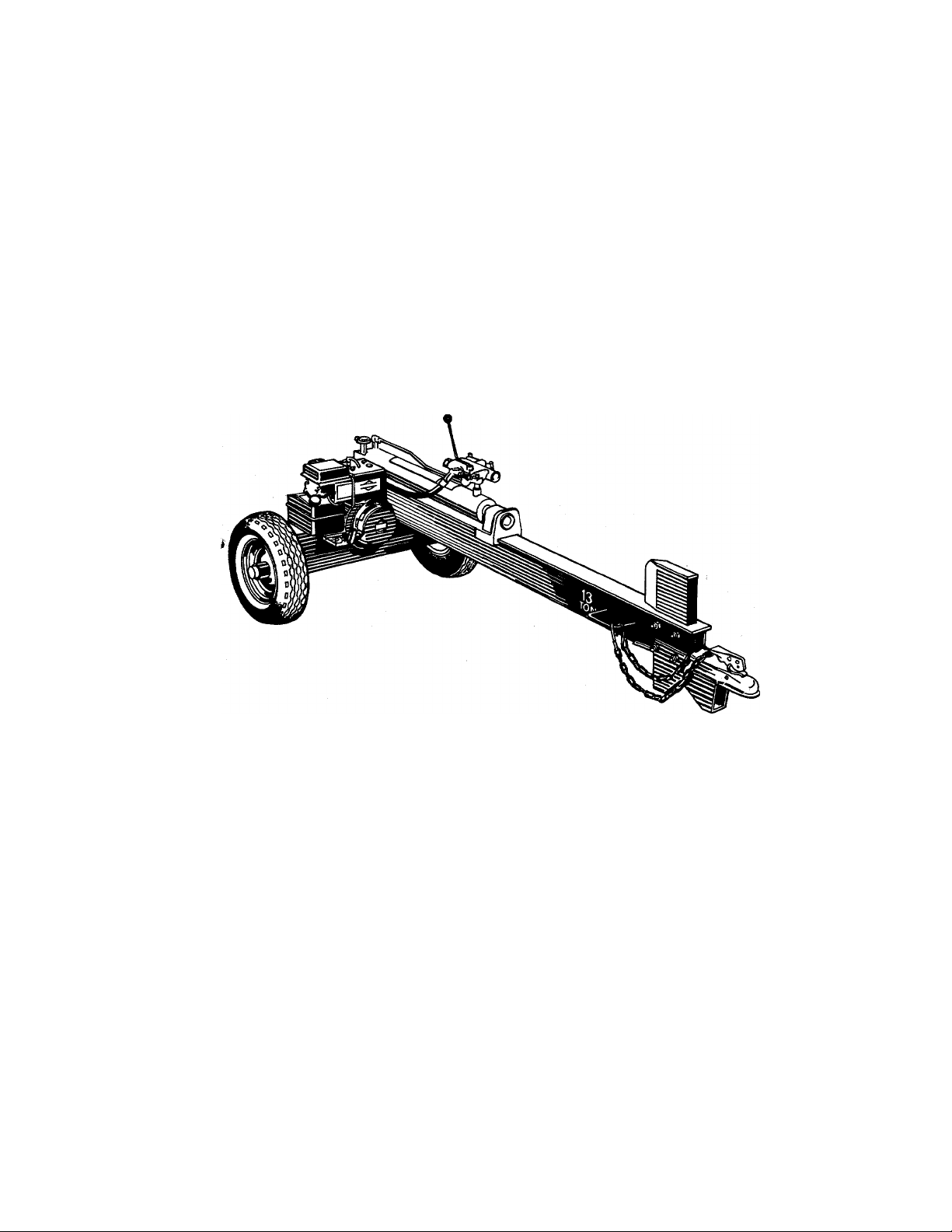
13 TON Model Number
HORIZONTAL 240-610-000
LOG SPLITTER
Important: Read Safety Rules and Instructions Carefully
2:
PRINTED IN U.S.A.
FORM NO. 770-6744E
Page 2

IMPORTANT
RULES FOR SAFE OPERATION
THIS SYMBOL POINTS OUT IMPORTANT SAFETY INS FRUCTIONS WHICH, IF NOT FOLLOWED, COULD ENDANGER THE PERSONAL
SAFETY AND/OR PROPERTY OF YOURSELF AND OTHilRS. READ AND FOLLOW ALL INSTRUCTIONS IN THIS MANUAL BEFORE AT
TEMPTING TO OPERATE YOUR LOG SPLIHER. FAILU iE TO COMPLY WITH THESE INSTRUCTIONS MAY RESULT IN PERSONAL IN
A
JURY. WHEN YOU SEE THIS SYMBOL-^HEED
ITS WARNING.
DANGER
Ai
Your log splitter was built to be operated iiccording to the rules for safe operation in this manual. As
with any type of power equipment, carelessness or error on the part of the operator can result in serious
injury. If you violate any of these rules, y lu may cause serious injury to yourself or others.
A
A
A
TRAINING
1. Before operating this splitter, read and understand this nanual
compietely. Become familiar with it for your own safety. To fail
to do so may cause serious injury. Do not aliow anyone to i ¡perate
your splitter who has not read this manual. Keep this mmual in
a safe place for future and regular reference and for o'dering
replacement parts.
2. Never use your splitter for any other purpose than splitting wood,
it is designed for this use and any other use may cause an injury.
Your log splitter is a precision piece of power equipmeni, not a
piaytoy. Therefore, excercise extreme caution at all timns.
3. Never allow children to operate your log splitter. Do not allov/ adults
to operate it without proper instruction. Only persons v^ell ac
quainted with these ruies of safe operation should be allowed to
use your log splitter.
4. Only the operator is to be near your log splitter during usn. Keep
all others, including pets and children, a minimum of 20 fent away
from your work zone. Flying wood can be hazardous. If £ helper
is assisting in loading logs, never activate the control until thi: helper
is clear of the area. More accidents occur when more tf an one
person operates the log splitter than at any other time.
5. No one should operate this unit while Intoxicated or whilt taking
medication that impairs the senses or reactions. A clear Tiind is
essential for safety. Never allow a person who is tired o other
wise not alert to use your splitter.
PREPARATION
Never wear loose clothing or jewelry that can be caught t y mov
ing parts of your log splitter and pull you into it. Keep i Nothing
away from all moving parts of your log splitter.
2. Wear proper head gear to keep hair away from movinii parts.
Always wear protective hearing devices as needed.
3. Always wear safety shoes. A dropped log can seriously inji ire your
foot.
4. Always wear safety glasses or goggles while operating yo ur split
ter. A piece of splitting log could fly off and hit your e/es.
5. If you wear gloves, be sure they are tight fitting without loo se cuffs
or draw strings.
6. Use your log splitter in daylight, or under good artificial light.
7. Never operate your splitter on slippery, wet, muddy or icy sur
faces. Safe footing is essential in preventing accidents. Never
operate your splitter while attached to a towing vehicle.
8. Only operate your splitter on level ground and not on the side of
a hill. It could tip, or rolling logs or poor footing could cause an
accident. Operating the splitter on level ground also prevents the
spillage of gasoline from the fuel tank.
9. Never attempt to move the log splitter over hilly or uneven terrain
without a tow vehicle or adequate help.
10. Always block the wheels to prevent mcwement of log splitter while
in operation.
11. Check the fuel before starting the engine. Gasoline is an extreme
ly flammable fuel. Do not fill the gasoline tank indoors, when the
engine is running, or while the engine is still hot. Replace gasoline
cap securely and wipe off any spilled gasoline before starting the
engine as it may cause a fire or explosion.
12. Both ends of each log must be cut as square as possible to help
prevent the log from riding out of the splitter during operation.
A
OPERATION
1. Stand behind the ram when operating. See illustration.
Page 3

2. Know how to stop the unit and disengage the controls.
3. Never place hands or feet between log and splitting wedge or be
tween log and ram during forward or reverse stroke. To do so
may result In crushed or amputated fingers or toes, or worse, you
may lose an arm or foot.
4. Do not straddle the splitter when using it. A slip in any position
could result in a serious injury.
5. Do not step over your log splitter when the engine is running. You
may trip or accidentally activate the ram if you step over. If you
need to get to the other side, walk around.
6. Never try to split two logs on top of each other. One may fly out
and injure you.
7. When loading the log splitter, place your hands on the side of the
log, not at the ends. Never attempt to load your splitter while the
ram is in motion. You may get caught by the ram and injured.
8. Only use your hand to operate the ram or control lever. Never
use your foot or a rope or any other extension device. This could
result in your ability to stop your splitter quickly enough and cause
injury.
9. Always keep fingers away from any cracks that open in the log
during splitting operation. They can quickly close and pinch or
amputate your fingers.
10. Never attempt to split woods across the grain. Some types of wood
may burst or fly out of your splitter and result in injury to you
or a bystander.
11. For logs that are not cut square, the longest portion of the log
should be rotated down and the most square end placed against
the ram.
12. Keep your work area clean. Immediately remove split wood around
your splitter so that you do not stumble over it.
13. Never move the log splitter while the engine is running.
^ 14. Never leave your log splitter unattended with the engine running.
Shut off the engine if you are leaving your splitter, even for a short
period of time. Someone could accidentally activate the ram and
be injured.
15. Do not run engine in an enclosed area. Exhaust gases contain car
bon monoxide. This odorless gas can be deadly when inhaled.
16. Be careful not to touch the muffler after the engine has been run
ning as it is HOT.
17. If the equipment should start to vibrate abnormally, stop the engine
and check immediately for the cause. Vibration is generally a warn
ing of trouble.
18. When cleaning, repairing or inspecting, make certain all moving
parts have stopped. Disconnect the spark plug wire and keep the
wire away from the plug to prevent accidental starting.
3. Replace all damaged or worn parts such as hydraulic hoses and
fittings immediately with manufacturer approved replacement parts.
4. Do not change the engine governor settings or overspeed the
engine. This increases the hazard of personal injury. The max
imum engine speed is preset by the manufacturer and is within
safety limits.
5. Do not alter your splitter in any manner such as attaching a rope
or extension to the control lever or adding to the width or height
of the wedge. Such alterations may cause your splitter to be unsafe.
6. Perform all recommended maintenance procedures before you use
your splitter.
7. Do not service or repair your log splitter without disconnecting
the spark plug wire.
8. Never store the equipment with gasoline in the tank inside of a
building where ignition sources are present, such as hot water
and space heaters, clothes dryers and the like. Allow the engine
to cool before storing in any enclosure.
9. Always store gasoline in an approved, tightly sealed container.
Store the container in a cool, dry place. Do not store in a building
where ignition sources are present.
10. To reduce fire hazard, keep engine free of grass, leaves, wood
chips, and excessive grease and oil.
11. The hydraulic system of your log splitter requires careful inspec
tion, along with the mechanical parts. Be sure to replace frayed,
kinked, or otherwise damaged hydraulic components.
12. Fluid escaping from a very small hole can be almost invisible. Do
not check for leaks with your hand. Escaping fluid under pressure
can have sufficient force to penetrate skin, causing serious per
sonal injury. Leaks can be located by passing a piece of card
board or wood over the suspected leak and looking for
discoloration.
13. Shouid it become necessary to loosen or remove any hydraulic
fitting or line, be sure to relieve all pressure by shutting off the
engine and moving the control handle back and forth several times.
14. Do not remove the cap from the hydraulic tank or reservoir while
your log splitter is running. Hot oil under pressure could cause
injury.
15. The pressure relief valve on your splitter is preset at the factory.
Do not adjust the valve. Only a qualified service technician should
perform this adjustment.
16. Completely drain fuel tank prior to storage. This guards against
accumulation of fuel fumes which could result in a fire hazard.
17. Never store log splitter outside without a waterproof cover. Rain
will cause rust on the inside of the cylinder.
A
MAINTENANCE
1. Do not operate your splitter in poor mechanical condition or when
in need of repair.
2. Periodically check that all nuts, bolts, screws, hose clamps and
hydraulic fittings are tight to be sure equipment is in safe working
condition. Where appropriate, check all safety guards and shields
to be sure they are in the proper position. Never operate your split
ter with safety guards, shields or other protective features removed.
These safety devices are for your protection.
NOTE: This unit is equipped with an internal combustion engine and should not be used on or near any unimproved forest-covered, brush-covered
or grass-covered land unless the engine’s exhaust system is equipped with a spark arrester meeting applicable local or state laws (if any). If
a spark arrester is used, it should be maintained in effective working order by the operator.
In the State of California the above is required by law (Section 4442 of the California Public Resources Code). Other states may have similar
laws. Federal laws apply on federal lands. A spark arrester for the muffler is available through your nearest engine authorized service dealer.
A
TOWING
1. This unit should not be towed on any street, highway or public
road. Any licensing needed to comply with the existing federal,
local or state vehicle requirements is the sole responsibility of the
purchaser.
2. Before towing, be certain the log splitter is correctly and securely
attached to the towing vehicle, and the safety chains are in place.
Leave slack in chains for turning allowance.
3. Do not allow anyone to sit or ride on your splitter. They can easily
fall off and be seriously injured.
Page 4
This unit has been shipped withoui
gasoline or oil in the engine. Aftei
assembly, refer to separate engine
manual for proper fuel and engine oi
information.
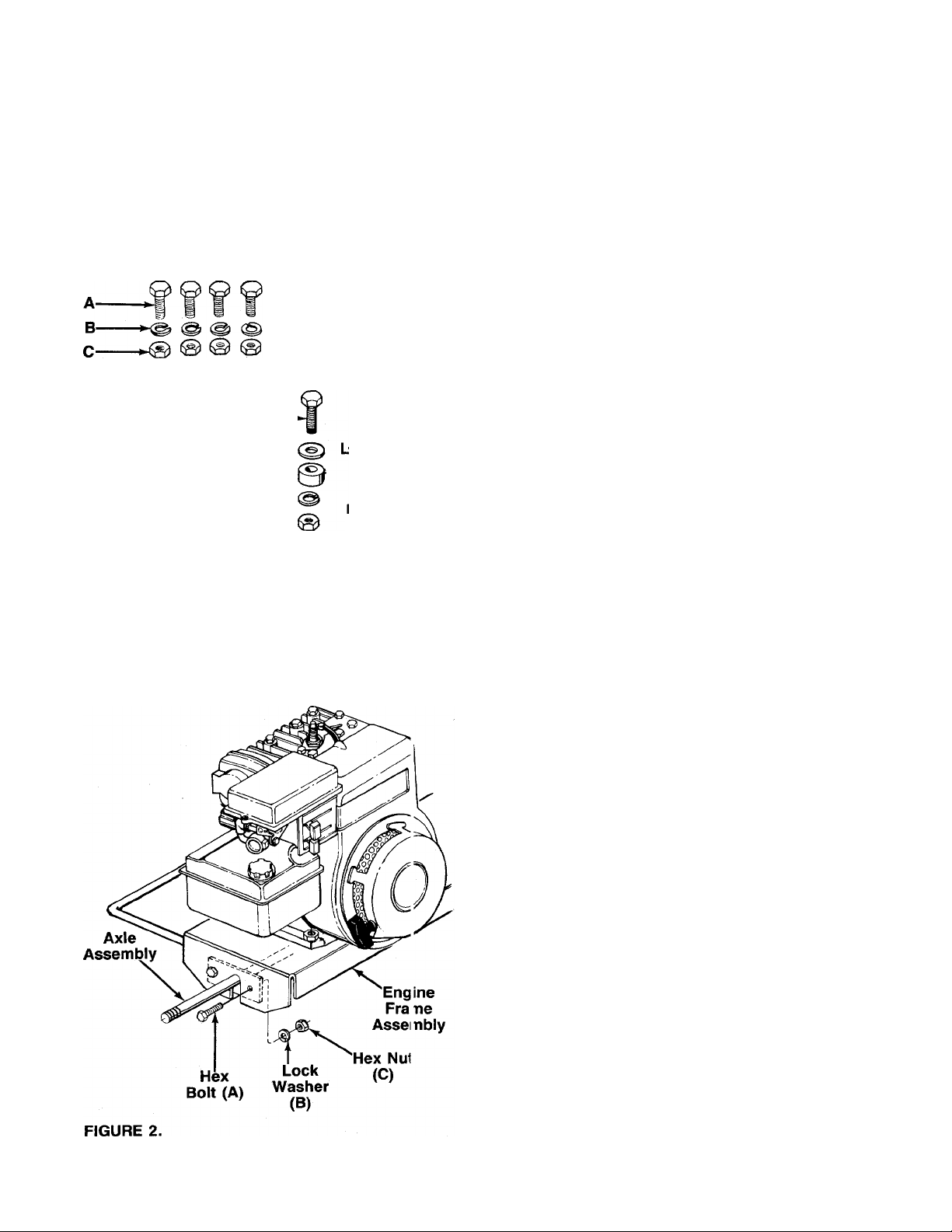
D-
E-
FIGURE 1.
IMPORTANT
G-
H-
IBJ-
K-
J—
O 0
ASSEMBLY
UNPACKING
Remove the log splitter and loose parts from the car
ton by cutting the corners of the carton. Make certain
all parts and literature have been removed from the car
ton before the carton is discarded.
Loose Parts in Carton:
(1) Axle Assembly
(1) Tow Hitch Assembly
(1) Beam Stand
(1) Tow Hitch Chain
(1) Hardware Pack
-Contents of Hardware Pack (See Figure 1):
A
C
G
J
K
Tools Required for Assembiy
(2) 9/16" Wrenches*
(1) Flat Blade Screwdriver
(2) Adjustable Wrenches
(1) Pair of Pliers
(1) Soft Hammer or Mallet
Hex Bolts 3/8-24 x 1" Long (Fine Thread)
(4)
B
Lock Washers 3/8" I.D.
(7)
Hex Nuts 3/8-24 (Fine) Thread
(4)
D
Spacers 3/4" I.D. x 1-1/2" Long
(2)
E
Castle Nuts 3/4-16 Thread
(2)
Cotter Pins
F
(2)
Hex Bolt 3/8-16 X 1-1/2" Long (Coarse Thread)
(1)
H
Fiat Washers 3/8" I.D.
(1)
Spacer 3/8" I.D. x 1/4" Long
(1)
Hex Nuts 3/8-16 (Coarse) Thrpad
(3)
Hex Bolts 3/8-16 X 3-1/4" Long (Coarse Thread)
(2)
L
Spacers 3/8" I.D. x 2" Long
(2)
Automotive Grease (not shown)
(1)
*Adjustable Wrenches may be used.
Other Materials Required for Assembly
Engine Oil
Unleaded Gasoline
Approximately 3 Gallons of Dexron II Automatic
Transmission Fluid
ATTACHING THE AXLE
1. Block up the engine frame assembly.
—2. Place the axle assembly in position inside the
engine frame assembly as shown in figure 2.
3. Secure with 1" long fine thread hex bolts (A), four
lock washers (B) and fine thread hex nuts (C), us
ing two 9/16" wrenches. Tighten securely.
4. Remove the protective plastic covers from the ends
of the axles.
Page 5
Lock
INSTALLATION OF WHEELS
1. Using a flat blade screwdriver, pry off the hub caps
which are attached to the wheels. Remove one
tapered roller bearing from inside each wheel.
2. Pack the roller bearings with the automotive grease
provided. (Do not grease inside the hub cap.)
3. Place one spacer (D) on each axle, then one wheel
-------and a tapered roller bearing. See figure 3.
4. Thread hex castle nuts (E) on axle. Using an ad
justable wrench, tighten castle nuts until snug, then
back off approximately 1/3 turn, or until one of the
slots on the castle nut lines up with hole in axle.
5. Insert cotter pins (F) through slot in castle nuts and
holes in axle. Secure by bending the ends of the
cotter pins in opposite directions, using a pair of
pliers.
^^NOTE
Make certain tapered roller bearings
were packed with grease. Save any
extra grease for greasing the beam
under “Initial Preparation’’ on page 6.
6. Place hub cap in position on wheel, and tap on with
a soft hammer or mallet.
ASSEMBLING THE BEAM STAND
The wedge is already assembled to the log splitter, and
is held in place with four 3-1/2" long hex bolts, lock
washers and hex nuts. The top two bolts and nuts are
tightened securely. The bottom two bolts and nuts have
been assembled loosely.
-1.
Remove the two bottom bolts, lock washers and
hex nuts from the beam and wedge.
2.
Place the beam stand in position as shown in figure
4. Secure to beam and wedge with hardware just
removed, using the larger holes in beam stand.
Tighten securely.
INSTALLING THE TOW HITCH
1. Attach the chain to the tow hitch as follows.
a. Place flat washer (H) on hex bolt (G).
b. Find the center link of the tow hitch chain. Place
hex bolt through the center link on the chain.
c. Place spacer (I) on hex bolt.
d. Insert hex bolt through hole in the top of tow
-----------
hitch as shown in figure 5.
e. Secure with one lock washer (B) and hex nut
(J). Tighten using two 9/16" wrenches.
Page 6

FIGURE 7.
Clevis Pin
Cotter Pin
2.
Place the hitch in position on the beam stand as
shown in figure 6. Piace spacer (L) inside the beam
stand. Insert hex bolt (K) through hitch, beam stand
and spacer. Secure with iock washer (B) and hex
nut (J). Assemble second bolt in same manner.
Tighten both bolts and nuts securely.
ATTACHING THE CONTROL HANDLE
1. The bottom of the control handle is aiready
attached to the valve with a cotter pin. Remove the
second cotter pin and clevis pin which are attached
to the valve only.
2. Place the handle in position, and secure using the
clevis pin and cotter pin. Secure by bending the
ends of the cotter pin in opposite directions. See
------
figure 7.
FINAL ASSEMBLY
1. Make certain all nuts, bolts and hose clamps are
tightened securely.
2. Before operating the log splitter, make certain to
follow the “Initial Preparation” instructions in the
Operation Section.
OPERATION
INITIAL PREPARATION
1. Place the log splitter on a firm, level surface.
2. Service engine with gasoline and oil as inst ucted
in the separate engine manual packed wit i your
log splitter.
3. Lubricate the area of the beam on which the ram
will slide with automotive grease.
4. Fill the reservoir tank (beam) and purge the a r from
the system as follows.
a. With the log splitter on a level surface, nsmove
the cap from the breather tube. See figure 8.
Remove the fluid check plug from the enc plate.
Fill the reservoir tank with Dexron II automatic
b.
transmission fluid until fluid starts to come out
of the hole. Replace the check plug.
Start the engine. Slowly move the control han
c.
dle forward and backward until the ram moves
smoothly in both directions.
Breather
Tube
Fluid
Check
Plug
FIGURE 8.
Page 7

d. Stop the engine. Remove the fluid check plug.
Add fluid as necessary until fluid starts to come
out of the hole. Replace the check plug.
e. Repeat steps “c” and “d” until the ram
operates smoothly and the fluid level is correct.
Then replace the breather cap securely.
Total capacity of the system is approximately 3
gallons.
WARNING
A
Do not operate the log splitter with
out the proper amount of transmission
fluid in the reservoir tank.
NOTE
Be certain to purge the air from the
hydraulic system as instructed above
after any repair work is performed on
the pump, valve or cylinder, if a hose
is removed for any reason or when
adding fluid to the reservoir.
BEFORE STARTING
Before each use, check the following:
1. Place the log spitter on a firm, level surface.
2. Remove the fluid check plug. See figure 8. If fluid
starts to come out of the hole, fluid level is correct.
If it does not, fill reservoir as instructed in step 4
of the previous section.
3. Lubricate the area of the beam on which the ram
will slide with automotive grease.
4. Fill gasoline tank as instructed in the separate
engine manual.
5. Attach spark plug wire to spark plug.
5. Repeat preceding instructions 3 and 4 until engine
fires. When engine starts, move choke lever
halfway between CHOKE and RUN.
6. Move throttle control lever to IDLE position for a
few minutes warm-up. Gradually move choke lever
to RUN position as engine warms up.
NOTE
In order to idle smoothly, a new
engine may require 3 to 5 minutes
running above slow idle speed. Idle
speed has been adjusted to be correct
after this break-in period.
7. If weather is cold, cycle the ram 6 to 8 times to cir
culate the hydraulic fluid, which will warm and thin
the fluid.
TO STOP ENGINE
1. Move throttle control lever to OFF position.
2. Disconnect spark plug wire from spark plug to pre
vent accidental starting while equipment is unat
tended.
TO START ENGINE
1. Place throttle control lever on the engine in FAST
position. See figure 9.
2. Place choke lever in CHOKE position (a warm
engine may not require choking).
3. Grasp starter handle and pull rope out slowly until
engine reaches start of compression cycle (rope
will pull slightly harder at this point). Let the rope
rewind slowly.
■I^note
When restarting a warm engine, be
careful to keep away from muffler and
other heated surfaces on the engine.
4. Pull rope with a rapid, continuous, full arm stroke.
Keep a firm grip on the starter handle. Let the rope
rewind slowly. Do not let starter handle snap back
against starter.
USING THE LOG SPLITTER
Use the log splitter only on a level, hard surface.
Never stand next to the ram when operating the iog
spiitter. Always stand behind the ram. See figure 10.
Never attempt to cut a log in half sideways. Always split
the log lengthwise. Maximum length of log to be split
is 25".
The control handle has three positions:
FORWARD (Push the control handle forward)—
Ram moves toward the splitting wedge. Control han
dle will return to neutral position as soon as handle
is released.
NEUTRAL (Middle position)—Ram stops in place.
REVERSE (Push the control handle to the rear)—
Ram returns. The control handle will lock in the
reverse position, and will return to neutral
automatically when the reverse stroke is complete.
Page 8

TO OPERATE LOG SPUTTER:
1. Set throttle at maximum speed.
2. Place log on beam. Hold in place with ha id.
3. Slowly move control handle forward until tf e ram
rests against the log. Release the control handle
(Neutral).
4. Remove your hand from the log and step tiehind
the ram. See figure 10.
5. Move control handle forward until log is s ilit.
6. Move the control handle to the rear to reti rn the
ram.
voir tank before each use. Refer to
under Operation Section.
Change the hydraulic fluid in the reservoir every 100
hours of operation. Remove the six hex bolts, lock
washers and hex nuts which hold the end plate to the
beam. See figure 11. Remove the plate, and drain the
fluid into a suitable container. Refill using only Dexron
II automatic transmission fluid, as instructed in the ‘‘In
itial Preparation” section of this manual, page 6. Also,
make certain to clean the strainer tube assembly.
NOTE
Drain the fluid and flush the reservoir
tank and hoses with kerosene whenever
any repair work is performed on the
tank, hydraulic pump or valve. Con
taminants in the fluid will damage the
hydraulic components. (Should be per
formed by an authorized service dealer.)
WARNING i
‘Before Starting”
A
Use extreme caution when working with
kerosene, as it is an extremely flammable
fluid.
A
I WARNING \
If the fluid becomes excessively hot at
any time during operation, stop the unit
and allow the fluid to cool down. Maxi
mum performance will not be obtained
from your log splitter if the fluid is too
hot. Use extreme caution as contacting
hot fluid could result in serious personal
injury.
TO TRANSPORT LOG SPLITTER
Attach the hitch to a towing vehicle, making certain to
latch securely. Attach the safety chains to the owing
vehicle.
MAINTENANCE
Always stop the engine and disconnect
the spark plug wire before performing
any maintenance or adjustments.
RESERVOIR FLUID
Check the hydraulic fluid level in the log splitter reser
Hex Bolts —Suction
Lock Washers Hose
Hex Nuts
FIGURE 11.
STRAINER TUBE ASSEMBLY
1. Loosen the hose clamp on the suction hose at the
beam. See figure 11. Disconnect the hose from the
beam.
2. Using an adjustable wrench, remove the fitting
from the beam.
3. Reach inside the end of the beam (end plate was
already removed), and pull out the strainer tube
assembly. See reference number 43 on page 12.
4. Clean the strainer tube assembly with kerosene.
Reassemble in reverse order.
5. Reassemble the end plate. Refill reservoir tank
with Dexron II automatic transmission fluid as in
structed under ‘‘Initial Preparation” in Operation
Section.
Page 9

BEAM AND SPLITTING WEDGE
Lubricate the beam where it contacts the ram with
grease before each use to obtain years of service.
HOSE CLAMPS
Check the hose clamps on the suction hose (attached
to bottom of the pump) for proper tightness before each
use. Check the hose clamps on the return hose (be
tween beam and cylinder) at least once a season.
ENGINE
Refer to the separate engine manual for all engine
maintenance instructions.
Maintain engine oil as instructed in the separate
engine manual packed with your unit. Read and follow
instructions carefully.
Service air cieaner every 25 hours under normal con
ditions. Clean every few hours under extremely dusty
conditions. Poor engine performance and flooding
usually indicates that the air cleaner should be ser
viced. To service the air cleaner refer to the separate
engine manual packed with your unit.
The spark plug should be cleaned and the gap reset
once a season. Spark plug replacement is recommend
ed at the start of each season; check engine manual
for correct plug type and gap specification.
Clean the engine regularly with a cloth or brush. Keep
the cooling system (blower housing area) clean to per
mit proper air circulation which is essential to engine
performance and life. Be certain to remove all dirt and
combustible debris from muffler area.
4.
Install the nylon “spider” insert into coupling half
on the engine shaft.
Place the coupling shield in position on the hex
5.
bolts. Rotate the keyway on the pump shaft so it
is toward the bottom.
Attach the coupling support bracket to the hex
6.
bolts, carefully sliding the coupling half over the
“spider” insert. Secure coupling shield and coup
ling support bracket with lock washers and hex
nuts. Tighten securely.
7.
Adjust the two coupling halves (steel) so there is
between .010" and .060" clearance between the
two halves (at least the thickness of a matchbook
cover, up to 1/16" maximum). See figure 12.
Tighten the set screw in the coupling half on the
pump shaft.
■^NOTE
Make certain proper clearance is ob
tained before tightening set screw.
PUMP
FLEXIBLE PUMP COUPLER
The flexible pump coupler is a nylon “spider” insert,
located between the pump and engine shaft. The align
ment is very critical. Over a period of time, the coupler
will harden and deteriorate. For a replacement flexible
pump coupler, order part number 717-0891.
\ WARNING j
A
Never hit the pump shaft in any manner,
as any blow will cause permanent
damage to the pump.
When replacing the flexible pump coupling, proceed
as follows.
1. Place the coupling half onto the engine shaft. Make
certain there is clearance between the coupling
half and the engine. Tighten the set screw.
2. Mount the pump onto the coupling support bracket.
Tighten securely.
3. Carefully slide coupling half onto pump shaft (make
certain set screw is loose). Slide the key into place
on the shaft.
CARBURETOR ADJUSTMENT
WARNING
A
If any adjustments are made to the
engine while the engine is running
(e.g. carburetor), keep clear of all moving
parts. Be careful of heated surfaces and
muffler.
Minor carburetor adjustment may be required to com
pensate for differences in fuel, temperature, altitude or
load. Improper adjustment will cause stalling when split
ting is under load, hard starting and higher fuel con
sumption.
Refer to the separate engine manuai packed with your
log splitter for carburetor adjustment information.
Page 10

NOTE
A DIRTY AIR CLEANER WILL CAUSE
ENGINE TO RUN ROUGH. BE CERTAIN
AIR CLEANER IS CLEAN AND AT
TACHED TO THE CARBURETOR
BEFORE ADJUSTING CARBURETOR.
DO NOT MAKE UNNECESSARY
ADJUSTMENTS. FACTORY SETTINGS
ARE SATISFACTORY FOR MOST
APPLICATIONS AND CONDITIONS.
OFF-SEASON STORAGE
To avoid engine problems, the fuel system should be
emptied before storage of 30 days or longer. Follow
these instructions.
1. Drain the fuel tank. Start the engine, and let it run
until the fuel lines and carburetor are empty.
WARNING I
A
DO NOT DRAIN FUEL WHILE
SMOKING, OR IF NEAR AN OPEN FIRE.
TIRE PRESSURE
Check sidewall of tire for manufacturer’s recommended
maximum tire pressure. If this information does not ap
pear on your tire, maximum tire pressure under any cir
cumstances is 30 p.s.i. Equal pressure shojld be
maintained on both tires.
INSTALLATION OF TIRE TO RIM
Ai WARNING^
The following procedure must be fol
lowed when removing or installing a
tire to the rim.
1. Be certain rim is clean and free of rust.
2. Lubricate both the tire and rim generous!]^
3. Never inflate to over 30 p.s.i. to seat beads. Ex
cessive pressure when seating beads may cause
tire/rim assembly to burst with force sufficient to
cause serious injury.
2.
Drain all the oil from the crankcase (this should be
done after the engine has been operated and is
still warm) and refill the crankcase with fresh oil.
Protect the inside of the engine for storage as
follows.
Remove spark plug, pour approximately Vz ounce
(approximately one tablespoon) of engine oil Into
cylinder and crank slowly to distribute oil. Replace
spark plug.
4.
Clean the engine and the entire log splitter
thoroughly.
Wipe unit with an oiled rag to prevent rust,
especially wedge and beam.
Store unit in a clean, dry area.
6.
__
^ NOTE
When storing any type of power
equipment in an unventilated or metal
storage shed, care should be taken to
rustproof the equipment by coating with
a light oil or silicone.
10
Page 11

N
Trouble
Trouble Shooting Guide
Possible Cause(s)
Corrective Action
Engine fails to start
Engine runs erratic
Engine overheats
Will not split logs
1. Fuel tank empty, or stale fuel.
2. Blocked fuel line.
3. Spark plug wire disconnected.
4. Faulty spark plug.
1. Unit running on CHOKE.
2. Spark plug wire loose.
3. Blocked fuel line or stale fuel.
4. Water or dirt in fuel system.
5. Dirty air cleaner.
6. Carburetor out of adjustment.
1. Engine oil level low.
2. Air flow restricted.
3. Carburetor not adjusted properly.
Reservoir fluid level low.
1. Fill tank with clean, fresh gasoline.
2. Clean fuel line.
3. Connect wire to spark plug.
4. Clean, adjust gap or replace.
1. Move choke lever to OFF position.
2. Connect and tighten spark plug
wire.
3. Clean fuel line; fill tank with clean
fresh gasoline.
4. Drain fuel tank. Refill with fresh
fuel.
5. Clean air cleaner as instructed in
separate engine manual.
6. Adjust carburetor (see Carburetor
Adjustment in separate engine
manual).
1. Fill crankcase with proper oil.
2. Remove blower housing and
clean as instructed in
separate engine manual.
3. Adjust carburetor (see Carburetor
Adjustment in separate engine
manual).
Check and fill reservoir tank as
instructed in Operation section
of this manual.
Leaking cylinder
NOTE: For repairs beyond the minor adjustments iisted above, piease contact your nearest authorized service dealer.
* Should be performed by an authorized service dealer only.
1. Broken seals.
2. Scored cylinder.
1. Replace seals.*
2. Replace cylinder.*
11
Page 12

Model 610
NOTE
Specifications subject to change without notice or
obligation.
T0TA.L CftPAClTY
3 GALLONS
DEXRONTt AUTOMATIC
TRANS. FLU\D
12
Page 13

Model 610
N
REF.
NO.
1 781-0038
2 710-0520
PART
NO.
CODE
Wedge Ass’y-
Hex Bolt 3/8-16 X 1.5" Lg.
PARTS LIST FOR MODEL 610 LOG SPLITTER
DESCRIPTION
(Gr. 5)
736-0262
3
4
713-0338
5 750-0507
6 710-0298
7 710-3130
FI-Wash. .375" I.D. x .87" O.D.
Chain—Tow Hitch
Spacer .38" I.D. x .625" O.D.
Hex Bolt 5/8-18 x 3.5" Lg.
Hex Bolt 3/8-16 X 3.25" Lg.
(Gr. 8)
8 727-0289
9 750-0261
10 736-0169
11 712-3017
12
781-0311
13 712-0337
14 736-0158
15 781-0343
16 738-0601
719-0269B
17
18
19 737-0238
737-0192
20
21 717-0942
22
737-0153
23 726-0146
24
737-0171
25 727-0430
Tow Hitch Ass’y.
Spacer .375" I.D. x .625" O.D.
L-Wash. 3/8" I.D.*
Hex Nut 3/8-16 Thd. (Gr. 5) 51
Beam Stand
Hex Nut 5/8-18 Thd.*
L-Wash. 5/8" I.D.*
452 Oil Tank Ass’y.
Shid. Bolt .62" Dia. x .475" 56 710-0237
Pusher Plate
638
Hydraulic Cyiinder
Pipe Nipple Vi" NPT x 2" Lg.
90° Solid Male Adapter
Control Valve
Return Elbow
Adjustable Hose Clamp
90° Solid Male Adapter 64
High Pressure Hydraulic Hose 66 781-0033B
29.5" Lg.
26 727-0435
Return Hose 3/4" I.D. x 23V2"
Lg-
27 727-0307
28 745-0174
29
781-0036
30 721-0204
31 720-0231
32 747-0709
33 710-1036
Metal Pressure Tube
Cap
Filler Tube Ass’y.
“0”-Ring .92" I.D.
N Ball Knob
N Control Handle
Hex Bolt 3/4-10 X 4.5" Lg.
34 710-0442 Hex Bolt 5/16-18 X 1.5" Lg.*
35 781-0361
36 721-0203A
37 712-0203
38 736-0364
Beam End Plate
N Gasket
Hex Nut 3/4-10 Thd.* 3/4" O.D.
L-Wash. 3/4" I.D.*
REF.
NO.
PART
NO.
39 712-0338
40 736-0275
41
712-0158
42
737-0259
43 781-0021
44
737-0191
CODE
DESCRIPTION
Hex Nut 1-1/16-12 Thd.
FI-Wash. .34" I.D. x .68" O.D.
Hex L-Nut 5/16-18 Thd.
90° Adapter 3/4" Hose
Strainer Tube Ass’y.
Adapter 1" x 1-1/16-12 Thd.
45 726-0132 Hose Clamp 5/8"
46 727-0429
47
737-0265
Suction Hose 1" I.D.
90° Adapter
48 717-0936 Two Volume Pump (Incl. Ref. 75)
49 712-0123
Hex Nut 5/16-24 Thd.*
50 736-0119 L-Wash. 5/16" I.D.*
714-0122 Sq. Key 3/16 x .75" Lg.
52 781-0097 Rear Coupling Support Bracket
53 710-0117 Hex Bolt 5/16-24 x 1.0" Lg.*
54
719-0278
Coupling Shield
55 717-0891 Flexible Coupling
Hex Bolt 5/16-24 x .62" Lg.
57
781-0098 Front Coupling Support Bracket
58
59
60
710-0363
—
710-0409
Hex Bolt 5/16-24 X 4.0" Lg.
Engine
Hex Bolt 5/16-24 x 1.75" Lg.*
61 712-0241 Hex Nut 3/8-24 Thd.*
62
710-0152 Hex Bolt 3/8-24 x 1.0" Lg.*
63 750-0442 Spacer .75" I.D. x 1.12" O.D.
781-0018
67
734-1016 Wheel Ass’y. Comp.
734-0872
68
734-0255
69
721-0168
Axle Assembly
N
Engine Frame Ass’y.
Tire Oniy
Air Valve
Bearing Seal
70 734-1017 Rim Only
71
741-0107
72
712-0299 Hex Slotted Nut 3/4-16 Thd.
73
734-0873
74
714-0162
Roller Bearing w/Race
Hub Cap
Cotter Pin 5/32" Dia.
75 714-3024 N Hi-Pro Key 1/8" X 1/2" Lg.
76 710-0604 Hex TT-Tap Scr. 5/16-18 x .62"
Lg.
77
721-0205 Gasket Washer 5/16" I.D. x
*For taster service obtain standard nuts, bolts and washers locally.
If these items cannot be obtained locally, order by part number and
size as shown on parts list.
13
NOTE: The engine is not under warranty by
the iog splitter manufacturer... If repairs or
service is needed on the engine, please
contact your nearest author
ized engine service outlet.
Check the “Yellow Pages” of
your telephone book under
“Engines—Gasoline.”
Find It Fast
In The
Yellow Pages
Page 14

Page 15

Page 16

parts; information
POWER EQUIPMENT PARTS AND SERVICE BRIGGS AND STRATTON, TECUMSEH AND PEERLESS PARTS ANQ
Parts and service are available through the authorized service firms listed SERVICE '/
below. All orflers should specify the model number of your uni:, part Briggs & Stratton, Tecumseh and Peerless parts and service should be
numbers, description of parts and the quantity of each part rec uired. handled by your nearest authorized engine service firm. Check the yellow
NOTE: If any parts are found to be missing or defrjctive upon assembly of this unit, write to advise the factory so that
immediate replacement can be made.
ARKANSAS NORTH LITTLE ROCK
Sutton’s Lawn Mower Shop
CALIFORNIA PORTERVILLE
Billious
..........................................
COLORADO DENVER
Spitzer Industrial Products Co. .. 6601 N.
FLORIDA JACKSONVILLE
Radco Distributors ...........................
Small Eng. Dist
ILLINOIS LYONS
Keen Edge Co................................... 8615 Ogden Ave.............6)534
INDIANA ELKHART
Parts & Sales Inc.
IOWA DUBUQUE
Power Lawn & Garden Equip.. . . 2551 J.F. Kennedy
MARYLAND BELTSVILLE
Center Supply Co............................ 6802 Industrial Dr.
MASSACHUSETTS SPRINGFIELD
Morton B. Collins Co
MICHIGAN MOUNT CLEMENS
Power Equipment Dist
MINNESOTA PLYMOUTH
Hance Distributing Inc
MISSOURI EARTH CITY
Oscar Wilson Engine & Parts ... 4159 Shoreline Dr..................63045
Automotive Equip. Service
NEW YORK CARTHAGE
Gamble Dist., Inc
..............................
............................
...............................
...........
......................
...................
...................
...............
5301 Roundtop Drive
Box 368, Rt. 4..................-/2117
75 North D Street
Washington St................60229
4909 Victor St.
Box 5459
HIALEAH
7995 W. 26th Court ... .33016
2101 Industrial Pkwy.
Box 277 ........................41)516
#208
..............................
300 Birnie Ave
340 Hubbard
12795 16th Ave. North .56 441
KANSAS CITY
3117 Holmes St
West End Ave.
Box 389
.............
......................
.........
...................
.....................
.............
.........................
£3257
32207
5;i001
20705
0' 107
46 043
64109
13319
pages of your telephone directory under the listing Engines—Gasoline,
Briggs & Stratton or Tecumseh Lauson.
NORTH CAROLINA
Dixie Sales Company
OHIO
Stebe’s Mid-State Mower Supply
Bleckrie, Inc
National Central
Burton Supply Co...........................
PENNSYLVANIA
EECO Inc
Bluemont Co
Frank Roberts & Sons
Scranton Auto Ignition Co
TENNESSEE
Ace Distributors..............................
Chilton Air Cooled Engine..............
TEXAS
Marr Brothers, Inc..
UTAH
Powered Products
VIRGINIA
RBI Corp
WASHINGTON
Equip. Northwest............................
WISCONSIN
Wisconsin Magneto Inc..................
PUERTO RICO
CIE & Associates, Inc
...................................
.......................................
..................................
........................................
....................
.............................
...................
..............
...
....................
.........................
....................
BROWNS SUMMIT
5920 Summit Ave
CARROLL
Box 366, 71 High St
CLEVELAND
7900 Lorain Ave
WADSWORTH
687 Seville Rd
YOUNGSTOWN
1301 Logan Ave.
Box 929
HARRISBURG
4021 N. 6th St
PITTSBURGH
11101 Frankstown Rd. .15235
PUNXSUTAWNEY
R.D. 2
SCRANTON
1133-35 Wyoming Ave. .18509
KNOXVILLE
2103 Magnolia................37917
NASHVILLE
319 4th Ave. S................37210
DALLAS %
423 E. Jefferson
SALT LAKE CITY
1661 N. Beck St
ASHLAND
101 Cedar Ridge Dr. . . 23Ò05
SEATTLE
1410 14th Ave
MILWAUKEE
4727 N. Teutonia St. . . .53209
AGUADILLA
102 North St...................00604
........................
.............................
...........
___
.............
...............
.................
.............
.............
................
27214
43112
44102
44281
44501
17110
15767
75203
84116
98122
WARRANTY FARTS AND SERVICE POLICY (0689)
The purpose of warranty is to protect the customer from defects in workmanship and materials, defects which are NOT detected at the time
of manufacture. It does not provide for the unlimited and unrestricted replacement of parts. Use and maintenance are the responsibility of the
customer. The manufacturer cannot assume responsibility for conditions over which it has no control. Simply put, if it’s the manufacturer’s fault,
it’s the manufacturer’s responsibility; if it’s the customer’s fau't, it’s the customer’s responsibility.
CLAIMS AGAINST THE MANUFACTURER’S WARRANTY
INCLUDES:
1. Replacement of Missing Parts on new equipment.
2. Replacement of Defective Parts within the warranty period.
3. Repair of Defects within the warranty period.
MTD PRODUCTS INC
P.O. ElOX 360900
All claims MUST be substantiated with the following
information;
1. Model Number, Serial Number and/or Data Code of unit in
volved.
2. Date unit was,purchased.
3. Date of Failure.
4. Nature of Failure.
CLEVELAND, OHIO 44136
 Loading...