

MTD 21a665b766-proline Parts Manuals
For Parts Call 606-678-9623 or 606-561-4983
For Parts Call 606-678-9623 or 606-561-4983
Operator’s Manual
Rear-tine Tiller Model
663B —Pony
663E —Pony
665B —ProLine
®
®
®
Engine styles vary by model
E663E —Pony® ES
IMPORTANT:READ SAFETY RULES AND INSTRUCTIONS CAREFULLY
Warning: This unit is equipped with an internal combustion engine and should not be used on or near any unimproved forest-covered, brush-
covered or grass-covered land unless the engine’s exhaust system is equipped with a spark arrester meeting applicable local or state laws (if any).
If a spark arrester is used, it should be maintained in effective working order by the operator. In the State of California the above is required by law
(Section 4442 of the California Public Resources Code). Other states may have similar laws. Federal laws apply on federal lands. A spark arrester
for the muffler is available by contacting the service department at Troy-Bilt LLC, P.O. Box 361131 Cleveland, Ohio 44136-0019.
TROY-BILT LLC, P.O. BOX 361131, CLEVELAND, OH 44136-0019
PRINTED IN USA FROM NO. 770-10597E
10/20/2006
www.mymowerparts.com
www.mymowerparts.com
Copy Model Number Here
Copy Serial Number Here
www.troybilt.com
TROY-BILT LLC
P. O. BOX
361 1 3 1
CLEVELAND, OH 44136
866-840-6483
330-558-7220
For Parts Call 606-678-9623 or 606-561-4983
For Parts Call 606-678-9623 or 606-561-4983
2
TABLE OF CONTENTS
Content Page
Calling Customer Support . . . . . . . . . . . . . . . . . . . . . . . . . . . . . . . . . . . . . . . . . . . . . . . . . . . .2
Safety . . . . . . . . . . . . . . . . . . . . . . . . . . . . . . . . . . . . . . . . . . . . . . . . . . . . . . . . . . . . . . . . . . . .3
Assembly . . . . . . . . . . . . . . . . . . . . . . . . . . . . . . . . . . . . . . . . . . . . . . . . . . . . . . . . . . . . . . . . .6
Features and Controls . . . . . . . . . . . . . . . . . . . . . . . . . . . . . . . . . . . . . . . . . . . . . . . . . . . . . . .11
Operation . . . . . . . . . . . . . . . . . . . . . . . . . . . . . . . . . . . . . . . . . . . . . . . . . . . . . . . . . . . . . . . . .14
Maintenance. . . . . . . . . . . . . . . . . . . . . . . . . . . . . . . . . . . . . . . . . . . . . . . . . . . . . . . . . . . . . . .20
Tiller Attachments . . . . . . . . . . . . . . . . . . . . . . . . . . . . . . . . . . . . . . . . . . . . . . . . . . . . . . . . . .28
Troubleshooting . . . . . . . . . . . . . . . . . . . . . . . . . . . . . . . . . . . . . . . . . . . . . . . . . . . . . . . . . . . .29
Parts List . . . . . . . . . . . . . . . . . . . . . . . . . . . . . . . . . . . . . . . . . . . . . . . . . . . . . . . . . . . . . . . . .30
Warrany Information . . . . . . . . . . . . . . . . . . . . . . . . . . . . . . . . . . . . . . . . . . . . . . . . . . . . . . . . .Back Cover
FINDING MODEL NUMBER
This Operator’s Manual is an important part of your new Rear-tine Tiller. It will help you assemble, prepare and maintain the unit for best performance. Please read and understand what it says.
Before you start assembling your new equipment, please locate the model plate on the equipment and copy the information from it in the space provided below. This information is very important if you need help from our Customer
Support Department or an authorized dealer.
• You can locate the model number by looking at the rear surface of the tine shield. A sample model plate is
explained below. For future reference, please copy the model number and the serial number of the equipment in
the space below
ENGINE INFORMATION
The engine manufacturer is responsible for all engine-related issues with regards to performance, power-rating, specifications, warranty and service. Please refer to the engine manufacturer’s Owner’s/Operator’s Manual packed separately with your unit for more information.
CALLING CUSTOMER SUPPORT
If you have difficulty assembling this product or have any questions regarding the controls, operation or maintenance
of this unit, please call the Customer Support Department.
Call 1- (330) 558-7220 or 1- (866) 840-6483 to reach a Customer Support representative. Please have
your unit’s model number and serial number ready when you call. See previous section to locate this information. You will be asked to enter the serial number in order to process your call .
For more details about your unit, visit our website at www.troybilt.com
www.mymowerparts.com
www.mymowerparts.com

For Parts Call 606-678-9623 or 606-561-4983
For Parts Call 606-678-9623 or 606-561-4983
Section
3
1
Safety Alert Symbol
This is a safety alert symbol. It is used in this
manual and on the unit to alert you to potential
hazards. When you see this symbol, read and
obey the message that follows it. Failure to obey
safety messages could result in personal injury or property damage.
TRAINING
1. Carefully read this
Owner’s Manual, the
separate Engine Owner’s
Manual, and any other
literature you may receive. Be thoroughly
familiar with the controls and the proper
use of the tiller and its engine. Know how
to stop the unit and disengage the controls quickly.
2. Never allow children to operate the
tiller. Never allow adults to operate the
tiller without proper instruction.
3. Keep the area of operation clear of all
persons, particularly children and pets.
4. Keep in mind that the operator or user
is responsible for accidents or hazards
occurring to other people, their property
and themselves.
PREPARATION
1. Thoroughly inspect the area where the
tiller is to be used and remove all foreign
objects.
2. Be sure all controls are released and
the Wheel Gear Lever is in ENGAGE
before starting the engine.
3. Do not operate the tiller without
wearing adequate outer garments. Avoid
loose garments or jewelry that could get
caught in moving parts.
4. Do not operate the tiller when barefoot
or wearing sandals, sneakers, or light
footwear. Wear protective footwear that will
improve footing on slippery surfaces.
5. Do not till near underground electric
cables, telephone lines, pipes or hoses. If
in doubt, contact your telephone or utility
company.
6. Warning: Handle fuel with care; it is
highly flammable and its vapors are explosive. Take the following precautions:
a. Store fuel in containers specifically
designed for this purpose.
b. The gas cap shall never be removed
or fuel added while the engine is
running. Allow the engine to cool
for several minutes before adding
fuel.
c. Keep matches, cigarettes, cigars,
pipes, open flames, and sparks
away from the fuel tank and fuel
container.
d. Fill fuel tank outdoors with extreme
care. Never fill fuel tank indoors.
Use a funnel or spout to prevent
spillage.
e. Replace all fuel tank and container
caps securely.
f. If fuel is spilled, do not attempt
to start the engine, but move the
machine away from the area of
spillage and avoid creating any
source of ignition until fuel vapors
have dissipated.
7. Never make adjustments when engine
is running (unless recommended by
manufacturer).
Safety
This machine meets voluntary safety standard B71.8
– 1996, which is sponsored by the Outdoor Power
Equipment Institute, Inc., and is published by the
American National Standards Institute.
WARNING
The engine exhaust from this product contains
chemicals known to the State of California to cause
cancer, birth defects or other reproductive harm.
OPERATION
1. Do not put hands or feet near or under
rotating parts.
2. Exercise extreme caution when on or
crossing gravel drives, walks, or roads.
Stay alert for hidden hazards or traffic. Do
not carry passengers.
3. After striking a foreign object, stop
the engine (and remove the ignition key
on electric start models), disconnect
the spark plug wire and prevent it from
touching the spark plug, carefully inspect
the tiller for any damage, and repair the
damage before restarting and operating
the tiller.
4. Exercise caution to avoid slipping or
falling.
5. If the unit should start to vibrate abnormally, stop the engine (and remove the
ignition key on electric start models).
Disconnect the spark plug wire and prevent
it from touching the spark plug, and check
immediately for the cause. Vibration is
generally a warning of trouble.
6. Stop the engine (and remove the ignition key on electric start models), disconnect the spark plug wire and prevent it
from touching the spark plug whenever
you leave the operating position, before
unclogging the tines, or when making any
repairs, adjustments or inspections.
www.mymowerparts.com
www.mymowerparts.com

For Parts Call 606-678-9623 or 606-561-4983
For Parts Call 606-678-9623 or 606-561-4983
4 Section 1: Safety
7. Take all possible precautions when
leaving the machine unattended. Stop the
engine. Remove ignition key on electric
start models. Disconnect spark plug wire
and move it away from the spark plug.
Move Wheel Gear Lever to ENGAGE.
8. Before cleaning, repairing, or inspecting, stop the engine, remove the ignition
key on electric start models, and make
certain all moving parts have stopped.
Disconnect the spark plug wire and
prevent it from touching the spark plug
to prevent accidental starting. On electric
start models, always remove the cable
from the negative side (–) of the battery.
9. Always keep the tiller tine hood flap
down, unless using the hiller/furrower
attachment.
10. Never use the tiller unless proper
guards, plates, or other safety protective
devices are in place.
11. Do not run engine in an enclosed
area. Engine exhaust contains carbon
monoxide gas, a deadly poison that is
odorless, colorless, and tasteless.
12. Keep children and pets away.
13. Never operate the tiller under
engine power if the Wheel Gear Lever
is in DISENGAGE (FREEWHEEL). In
this position, the wheels will not hold
the tiller back and the revolving tines
could propel the tiller rapidly, possibly
causing loss of control. Always move
the Wheel Gear Lever to ENGAGE before
starting the engine or engaging the tines/
wheels with the Forward Clutch Control or
the Reverse Clutch Control.
14. Be aware that the tiller may unexpectedly bounce upward or jump
forward if the tines should strike
extremely hard packed soil, frozen
ground, or buried obstacles like large
stones, roots, or stumps. If in doubt
about the tilling conditions, always use
the following operating precautions to
assist you in maintaining control of the
tiller:
a. Walk behind and to one side of
the tiller, using one hand on the
handlebars. Relax your arm, but
use a secure hand grip.
b. Use shallower depth regulator set-
tings, working gradually deeper
with each pass.
c. Use slower engine speeds.
d. Clear the tilling area of all large
stones, roots and other debris.
e. Avoid using downward pressure on
handlebars. If need be, use slight
upward pressure to keep the tines
from digging too deeply.
f. Before contacting hard packed soil
at the end of a row, reduce engine
speed and lift handlebars to raise
tines out of the soil.
g. In an emergency, stop tines and
wheels by releasing whichever
Clutch Lever is engaged. Do not
attempt to restrain the tiller.
15. Do not overload the tiller’s capacity
by attempting to till too deeply at too fast
a rate.
16. Never operate the tiller at high transport speeds on hard or slippery surfaces.
Look behind and use care when backing
up.
17. Do not operate the tiller on a slope
that is too steep for safety. When on
slopes, slow down and make sure you
have good footing. Never permit the tiller
to freewheel down slopes.
18. Never allow bystanders near the unit.
19. Only use attachments and accessories
that are approved by the tiller
manufacturer.
20. Use tiller attachments and accessories when recommended.
21. Never operate the tiller without good
visibility or light.
22. Never operate the tiller if you are
tired, or under the influence of alcohol,
drugs or medication.
23. Operators shall not tamper with the
engine-governor settings on the machine;
the governor controls the maximum safe
operating speed to protect the engine and
all moving parts from damage caused by
overspeed. Authorized service shall be
sought if a problem exists.
24. Do not touch engine parts which may
be hot from operation. Let parts cool
down sufficiently.
25. The battery on electric start model
tillers contains sulfuric acid. Avoid
contact with skin, eyes, or clothing. Keep
out of the reach of children.
Antidote–
diately with lots of water.
Antidote–
ties of water or milk. Follow with milk of
magnesia, beaten eggs or vegetable oil.
Call a doctor immediately.
Antidote–
for 15 minutes. Get prompt medical
attention.
26. Batteries produce explosive gases.
Keep sparks, flame, and smoking materials
away. Ventilate when charging batteries or
when using a battery in an enclosed space.
ALWAYS wear safety goggles when working
near batteries.
27. Please remember: You can always
stop the tines and wheels by releasing
the Forward Clutch Control Lever or the
Reverse Clutch Control knob (whichever
control you have engaged), or by moving
the Engine Throttle Control Lever (located
on engine) to STOP on recoil start models
or by turning the ignition key to OFF on
electric start models.
28. To load or unload the tiller, see the
instructions in Section 4 of this Manual.
29. Use extreme caution when reversing or
pulling the machine towards you.
30. Start the engine carefully according to
instructions and with feet well away from
the tines.
31. Never pick up or carry a machine while
the engine is running.
External Contact: Flush imme-
Internal: Drink large quanti-
Eye Contact: Flush with water
MAINTENANCE AND STORAGE
1. Keep the tiller, attachments and accessories in safe working condition.
2. Check all nuts, bolts, and screws at
frequent intervals for proper tightness to
be sure the equipment is in safe working
condition.
3. Never store the tiller with fuel in the
fuel tank inside a building where ignition
sources are present such as hot water and
space heaters, furnaces, clothes dryers,
stoves, electric motors, etc. Allow engine to
cool before storing in any enclosure.
www.mymowerparts.com
www.mymowerparts.com
STOP
STOP
For Parts Call 606-678-9623 or 606-561-4983
For Parts Call 606-678-9623 or 606-561-4983
Section 1: Safety 5
4. To reduce the chances of a fire
hazard, keep the engine free of grass,
leaves, or excessive grease.
5. Store gasoline in a cool, well-ventilated area, safely away from any sparkor flame-producing equipment. Store
gasoline in an approved container,
safely away from the reach of children.
6. Refer to the Maintenance section of
this Manual and in the separate Engine
Owner’s Manual for instructions if the
tiller is to be stored for an extended
period.
7. Never perform maintenance while
the engine is running or the spark plug
wire is connected, except when specifically instructed to do so.
8. If the fuel tank has to be drained, do
this outdoors.
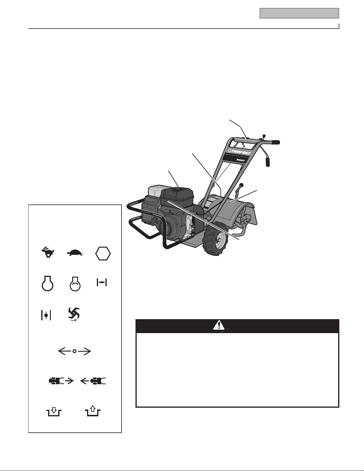
Operating Symbols
Various symbols (shown here, with
word descriptions) may be used on the
tiller and engine.
DECALS
For your safety and the safety of others,
various safety message decals are on your
unit (see Figure below). Keep the decals
clean and legible at all times. Contact your
local service dealer or the factory for
Control Descriptions
Tine Warning (on right
side of hood flap)
Starting Stabilization (on
top of engine or fuel tank)
replacements if any decals are damaged or
missing.
Refer to the Parts List pages for decal
locations and part numbers.
Operating Instructions and
Warning Messages
Hot Surfaces/Moving Belts
(on top of belt cover)
FAST
STOP
CHOKE
OFF
LEVER DIRECTION
ENGAGED
SLOW
START
ROTATING
TINES
TILLER DIRECTION
REVERSE
DISENGAGED
STOP
CHOKE
ON
R
Figure 1: Location of Safety and Operating Decals
WARNING
TO AVOID SERIOUS INJURY:
• READ THE OWNER’S MANUAL.
• KNOW LOCATIONS AND FUNCTIONS OF ALL CONTROLS.
• KEEP ALL SAFETY DEVICES AND SHIELDS IN PLACE AND WORKING.
• NEVER ALLOW CHILDREN OR UNINSTRUCTED ADULTS TO OPERATE TILLER.
• SHUT OFF ENGINE AND DISCONNECT SPARK PLUG WIRE BEFORE MANUALLY UNCLOG
GING TINES OR MAKING REPAIRS.
• KEEP BYSTANDERS AWAY FROM MACHINE.
• KEEP AWAY FROM ROTATING PARTS.
• USE EXTREME CAUTION WHEN REVERSING OR PULLING THE MACHINE TOWARDS YOU.
-
www.mymowerparts.com
www.mymowerparts.com
WARNING
For Parts Call 606-678-9623 or 606-561-4983
For Parts Call 606-678-9623 or 606-561-4983
6
Section
To prevent personal injury or property
damage, do not start the engine until all
assembly steps are complete and you
have read and understand the safety and
operating instructions in this Manual.
INTRODUCTION
Carefully follow these assembly steps to
correctly prepare your tiller for use. It is
recommended that you read this Section
in its entirety before beginning assembly.
INSPECT UNIT
Inspect the unit and carton for damage
immediately after delivery. Contact the
carrier (trucking company) if you find
or suspect damage. Inform them of the
damage and request instructions for filing
a claim. To protect your rights, put your
claim in writing and mail a copy to the
carrier within 15 days after the unit has
been delivered. Contact us at the factory if
you need assistance in this matter.
UNPACKING AND ASSEMBLY
INSTRUCTIONS
STEP 1: UNPACKING INSTRUCTIONS
1. Remove any card board inserts and
packaging material from the carton.
Remove any staples from the bottom of
the carton and remove the carton.
2. Cut the large, plastic tie strap that
secures the transmission tube to the shipping pallet. Leave the handlebars on top
of the tiller to avoid damaging any cables.
3. A bag with loose hardware is inside
the literature envelope. Check the contents against the following list and Figure
2-1.
NOTE: For electric start units, a second
hardware bag is located near the battery.
4. The tiller is heavy. You should not
attempt to remove it from the shipping
platform until instructed to do so in these
“Assembly” steps.
2
Assembly
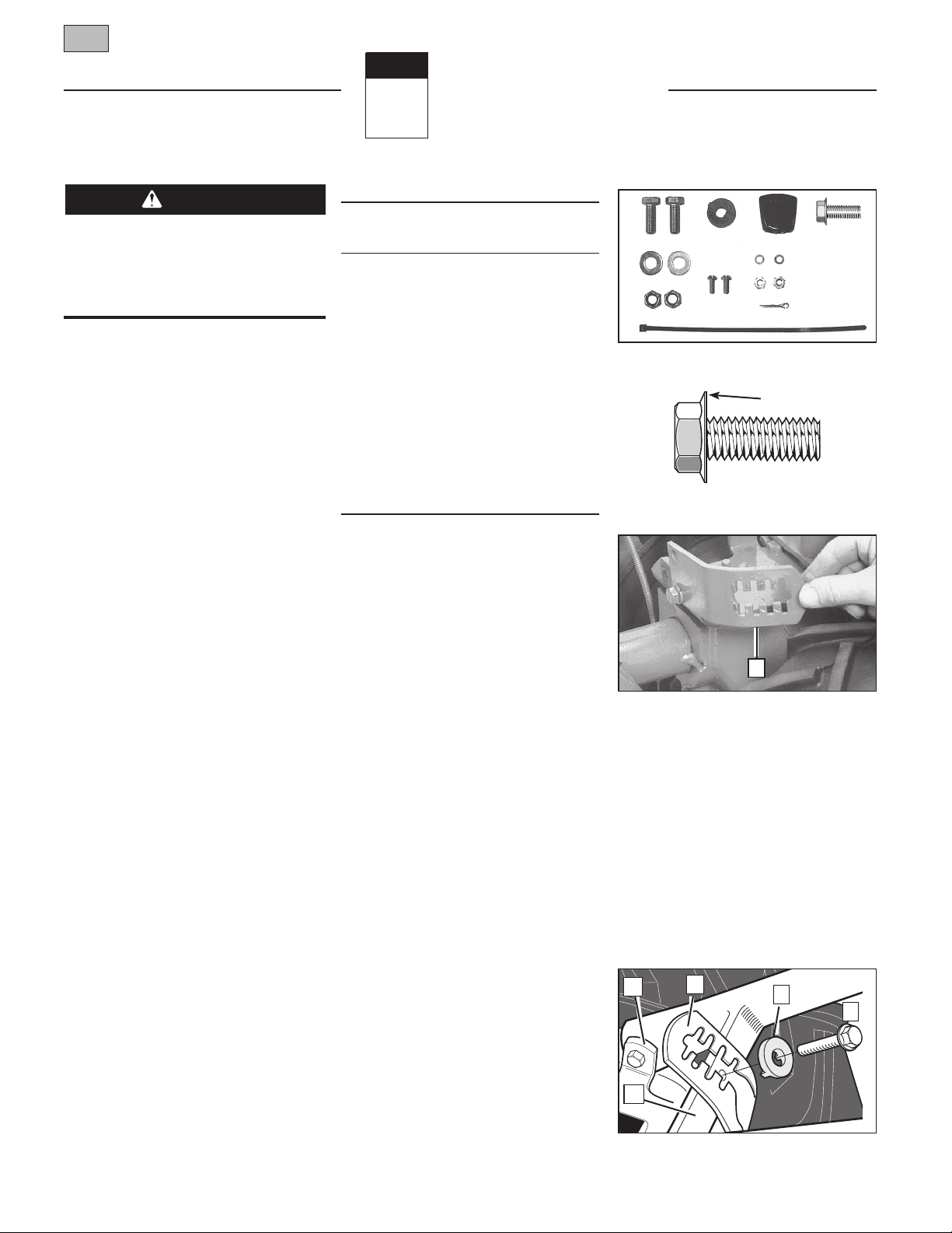
HARDWARE BAG PARTS LIST
Fig.
Ref. Qty. Description
1 2 3/8-16 x 1" Hex Hd. Screw
2 1 Keyed Washer
3 1 Wheel Gear Lever Knob
4 1 Height Adjustment Flange
Screw (See Figure 2-1A)
5 2 3/8" Flat Washer
6 2 #10 Lockwasher
7 2 3/8"-16 Nylock Lock Nut
8 2 #10-32 x 1/2" Round Hd.
Screw
9 2 #10-32 Nut
10 1 Cotter Pin (not used)
11 4 Plastic Tie Strap (2 not used)
Tools/Materials Needed
for Assembly
(1) 3/8" open-end wrench*
(1) 7/16" open-end wrench* (electric
start unit only)
(2) 9/16" open-end wrench*
(1) 7/8" open-end wrench or 8" long
adjustable wrench
(1) Scissors (to trim plastic ties)
(1) Ruler
(1) Small board (to tap plastic knob on
lever)
(1) Tire pressure gauge
(1) Clean oil funnel
(1) Clean, high-quality motor oil. Refer
to the separate Engine Owner’s
Manual for motor oil specifications
and quantity required.
* Adjustable wrenches may be used.
IMPORTANT: Motor oil must be added to
the engine crankcase before the engine
is started. Follow the instructions in this
“Assembly” Section and in the separate
Engine Owner’s Manual.
NOTE: LEFT and RIGHT sides of the tiller
are as viewed from the operator’s position
behind the handlebars.
STEP 2: ATTACH HANDLEBARS
1. On electric start units, remove one
screw and lockwasher from the curved
2
5
7
Figure 2-1: Loose hardware (shown in
reduced size).
Figure 2-1A Handlebar height adjustment
uses the flange head screw.
8
11
31
6
10
Flange
4
9
A
Figure 2-2: On electric start units, move
height adjustment bracket aside.
height adjustment bracket (A, Figure 2-2),
loosen the second screw, and swing the
bracket to one side.
2. Cut the large, plastic cable ties that
secure the handlebar ends to the handlebar mounting tabs on the transmission
top cover.
3. Gently lift handlebar (do not overstretch attached cable) and place handlebar cross-brace (B, Figure 2-3) in front of
curved height adjustment bracket (C).
M
C
E
F
B
Figure 2-3: Forward clutch control cable not
shown for clarity.
www.mymowerparts.com
www.mymowerparts.com
For Parts Call 606-678-9623 or 606-561-4983
For Parts Call 606-678-9623 or 606-561-4983
Section 2: Assembly 7
4. With the forward clutch cable (N,
Figure 2-4) on the inside of handlebar, position the handlebar ends on the
outside of the two mounting tabs (M,
Figure 2-3) on the transmission top cover.
NOTE: The curved handlebar height
adjustment bracket appears as shown in
C, Figure 2-3 for non-electric start units.
For electric start units, the bracket is loosened and moved to one side.
5. Loosely attach the handlebars to
the mounting tabs with two 3/8-16 x 1"
screws (heads of screws go to inside of
tabs), 3/8" flat washers and 3/8"-16 lock
nuts (O, Figure 2-4).
6. On electric start units, reattach the
C
N
Figure 2-4: Attach handlebars.
height adjustment bracket (A, Figure 2-2).
Tighten both screws securely. Make sure
the handlebar cross-brace (B, Figure 2-3)
is under the bracket.
7. Move the handlebars up or down
to align the threaded hole in the crossbrace with one of the four slots in the
curved height adjustment bracket. Place
the keyed washer (E, Figure 2-3) on the
flange head height adjustment screw (F)
with the raised keys (edges) of the washer
facing down.
8. Thread the height adjustment screw (F,
Figure 2-3) into the hole in the handlebar
cross-brace, making sure that the raised
keys on the washer fit into the slot on the
height adjustment bracket. Tighten the
height adjustment screw securely. Next,
securely tighten the two screws and nuts
in the ends of the handlebar (M, Figure
2-3).
9. To remove the tiller from its shipping
platform, first carefully unwrap the wheel
gear cable (with attached lever - see
Figure 2-5) from around the chassis.
Move the Wheel Gear Lever (G) to the
DISENGAGE position--this allows the
wheels to rotate freely. Use the handlebars to roll the tiller off the platform.
O
G
Figure 2-5: Carefully unwrap Wheel Gear
Lever and move lever to DISENGAGE.
NOTE: The Wheel Gear Lever will be
installed later in this procedure.
IMPORTANT:
tion only when the engine is not running.
Before starting the engine, the Wheel
Gear Lever must be placed in the ENGAGE
position (see Section 3 for details).
Use the DISENGAGE posi-
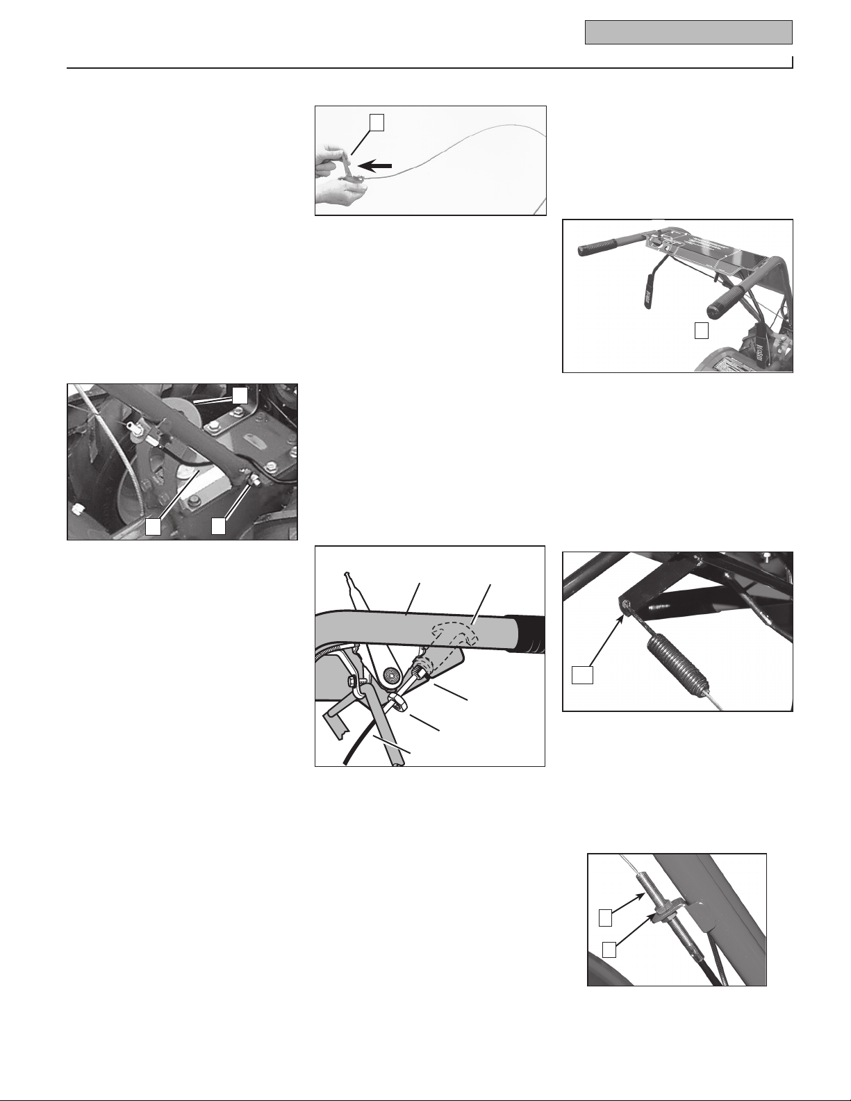
STEP 3: ATTACH REVERSE
CLUTCH CONTROL CABLE
1. Carefully unwrap the reverse clutch
control cable (H, Figure 2-6) from its
shipping position and route it up along
the inside edge of the left side handlebar.
A knob and large hex nut (I) is installed
on the cable.
2. Insert the cable into the slot in the
Left Side
Handlebar
Reverse Clutch
Control Knob
Slot in
Control
Panel
I
H
Figure 2-6: Attach reverse clutch control
assembly to slotted hole in handlebar panel.
control panel and fit the threaded assembly into the hole in the slot (see Figure
2-6). Be sure that the flat side of the
threaded assembly is aligned with the flat
side of the hole. Slide the hex nut (I) up
the cable and tighten it securely.
3. Test the function of the reverse clutch
control cable by pulling the knob out and
releasing it. The knob should return to
its neutral position against the tapered
bushing. If it doesn’t, contact your local
dealer or the factory for technical
assistance.
STEP 4: ATTACH FORWARD
CLUTCH CONTROL CABLE
1. Remove any fasteners (rubber bands,
tape, etc.) that may secure the Forward
Clutch Control levers (J, Figure 2-7) to the
handlebar.
J
Figure 2-7: Forward Clutch Control levers
(J). Forward clutch control linkage (K).
2. The forward clutch control cable (with
attached spring) is hanging loosely near
the right-side wheel. Being careful not to
kink or stretch the cable, insert the z-connector (L, Figure 2-8 – end of the spring)
into the hole at the end of the forward
clutch control linkage (K, Figure 2-7).
L
Figure 2-8
3. Attach the cable adjuster (A, Figure
2-9) to the bracket on the right-side handlebar. Use two 1/2" wrenches to loosen
the two jam nuts (B) just enough to slide
the cable adjuster onto the bracket. Then
hand tighten the jam nuts.
A
B
Figure 2-9
www.mymowerparts.com
www.mymowerparts.com

CAUTION
For Parts Call 606-678-9623 or 606-561-4983
For Parts Call 606-678-9623 or 606-561-4983
8 Section 2: Assembly
Incorrect cable adjustment could cause
the wheels and tines to rotate unexpectedly. Follow adjustment procedures
carefully. Failure to do so could result
in personal injury or property damage.
4. Check for correct spring/cable tension
as instructed in Section 5, Checking and
Adjusting Forward Clutch Belt Tension.
5. When tension is correct, tighten the
two jam nuts (B) securely.
STEP 5: CHECK TRANSMISSION
GEAR OIL LEVEL
The transmission was filled with gear oil
at the factory. However, be sure to check
the oil level at this time to make certain it
is correct.
IMPORTANT: Do not operate the tiller
if the gear oil level is low. Doing so will
result in severe damage to the transmission components.
1. With the tiller on level ground, pull the
Depth Regulator Lever (R, Figure 2-13)
back and then slide it to the second notch
from the top. NOTE: If the lever does not
move, lift the tine hood flap and look for a
plastic tie securing the lever in place. Cut
and remove the tie.
2. Remove the oil level check plug (M,
Figure 2-10) on the left-side of the transmission. (Due to dried paint on the plug
threads, it may require some force to
remove the plug the first time.) The gear
oil level is correct if oil starts to flow out
of the hole as the plug is removed. If so,
securely reinstall the plug.
M
Figure 2-10: Gear oil level check plug.
3. If oil does not flow from the check
hole, add oil as follows:
NOTE: Do not use automatic transmission
fluid or motor oil in the transmission.
(a) Clean area around the fill hole (N,
Figure 2-11) and unscrew gear oil fill
plug.
N
Figure 2-11: Adding gear oil.
(b) If adding only a few ounces of gear
oil, use API rated GL-4 or GL-5 gear
oil having a viscosity of SAE 140, SAE
85W-140 or SAE 80W-90. If refilling an
empty transmission, use only GL-4 gear
oil having a viscosity of SAE 85W-140 or
SAE 140.
(c) Using a clean funnel, slowly add gear
oil until it flows from the gear oil level
check hole (N, Figure 2-11).
(d) Reinstall and tighten securely the gear
oil fill plug (M, Figure 2-10).
STEP 6: ATTACH WHEEL GEAR
LEVER
1. Insert the Wheel Gear Lever (P, Figure
2-12) up through the slot in the control
panel that is labeled “WHEEL GEAR.”
2. Insert two #10-32 x 1/2" round head
screws down through the “+” marks
on the control panel decal and securely
attach the wheel gear mounting bracket
using two #10 lockwashers and #10-32
nuts.
3. Use a small board to tap the Wheel
Gear Lever knob securely onto the lever.
4. Secure the wheel gear cable and the
reverse clutch control cable to the leftside handlebar with two plastic ties (S,
Figure 2-13) located about two feet apart.
Snip off any excess tie length with
scissors.
STEP 7 ATTACHING THE BATTERY
CABLES (MODEL E663E)
The positive battery terminal is marked
Pos. (+). The negative battery terminal is
marked Neg. (–).
1. Remove the hex bolt and hex nut from
the positive cable (heavy red wire).
2. Remove the plastic cover from the
positive battery terminal and attach the
positive cable to the positive battery terminal (+) with the bolt and hex nut. Make
certain that the rubber boot covers the
positive terminal to help protect it from
P
Figure 2-12: Attach Wheel Gear Lever.
S
Figure 2-13: Attach wheel gear cable and
reverse clutch cable with cable ties (S).
corrosion.
3. Remove the hex bolt and hex nut from
the negative cable (heavy black wire).
4. Remove the black plastic cover from
the negative battery terminal and attach
the negative cable to the negative battery
terminal (–) with the bolt and hex nut.
IMPORTANT:
If the battery is put into service after the
•
date shown on top of battery, charge the
battery as instructed in the Maintenence
section of this manual prior to operating
the tiller.
STEP 8: CHECK AIR
PRESSURE IN TIRES
Use a tire pressure gauge to check the air
pressure in both tires. Deflate or inflate
both tires equally to between 15 PSI
and 20 PSI). Be sure that both tires are
inflated equally or the unit will pull to one
side.
STEP 9: CHECK HARDWARE
FOR TIGHTNESS
Inspect the hardware on the unit and
tighten any loose screws, bolts and nuts.
www.mymowerparts.com
www.mymowerparts.com
WARNING
DANGER
WARNING
For Parts Call 606-678-9623 or 606-561-4983
For Parts Call 606-678-9623 or 606-561-4983
Section
9
3
Features and Controls
Before operating your machine, carefully read and understand all safety,
controls and operating instructions
in this Manual, the separate Engine
Owner’s Manual, and on the decals on
the machine.
Failure to follow these instructions can
result in serious personal injury.
INTRODUCTION
This Section describes the location and
function of the controls on your tiller.
Refer to the following section “Operation”
for detailed operating instructions.
Practice using these controls, with the
engine shut off, until you understand the
operation of the controls and feel confident with them.
IMPORTANT: Refer to the separate engine
manufacturer’s Engine Owner’s Manual
for information about the controls on the
engine.
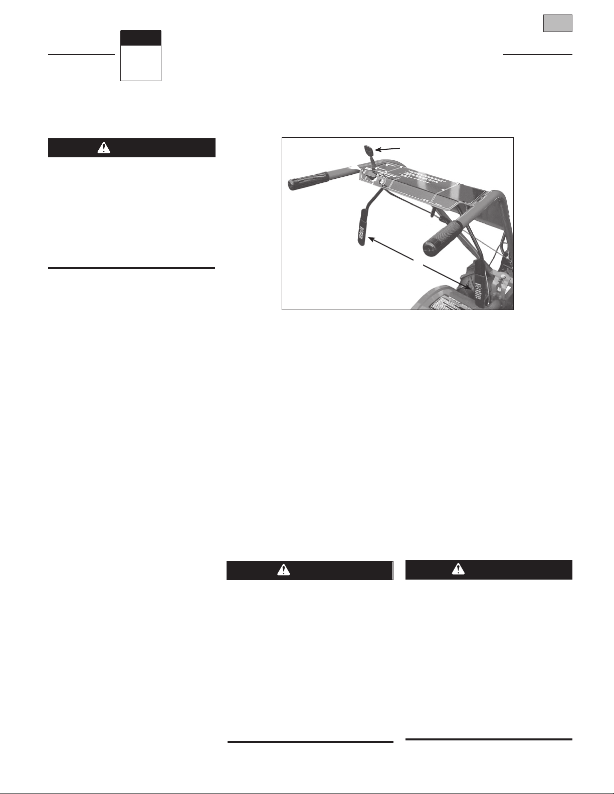
WHEEL GEAR LEVER
This lever (A, Figure 3-1) has two positions: ENGAGE and DISENGAGE.
In the ENGAGE position, the wheels will
start turning when either the Forward
Clutch Control or the Reverse Clutch
Control is engaged (the tines will also
start turning when either clutch is
engaged).
C
Figure 3-1: Controls located on handlebar.
The DISENGAGE position places the
wheels in the freewheeling mode to allow
the unit to be moved without the engine
running. Use the DISENGAGE position
only when the engine is not running. See
“DANGER” statement that follows.
To shift to ENGAGE, gently (do not force)
move the lever forward while also rolling
the tiller a few inches forward or backward. Moving the tiller helps to align the
shift mechanism with the transmission
wheel drive gears.
To shift to DISENGAGE (freewheel), move
the lever rearward, without rolling the
tiller. The wheels will roll freely
when the lever is properly set in the
DISENGAGE position.
Never place the Wheel Gear Lever in
DIS E N G A GE (Fr e e w h eel) wh e n the
engine is running.
Having t h e Whee l Gear L e v e r in
DISENGAGE and then engaging the tines/
wheels with either the Forward Clutch
Control or the Reverse Clutch Control
could allow the tines to propel the tiller
rapidly forward or backward.
Failure to follow this instruction could
result in personal injury or property
damage.
A
B
FORWARD CLUTCH CONTROL
The two interconnected levers (B, Figure
3-1) control the engagement of forward
drive to the wheels and tines.
To Operate the Forward Clutch Control:
1. Before engaging the Forward Clutch
Control, put the Wheel Gear Lever in
the ENGAGE position (see “WARNING”
below).
2. Pull up and hold one or both of the
levers against the handlebar grips to
engage the wheels and tines.
3. Release BOTH levers to disengage
(stop) the wheels and tines. All forward
motion will stop (the engine will continue
to run).
Never engage the wheels and tines
with the Forward Clutch Control or the
Reverse Clutch Control unless the Wheel
Gear Lever is in ENGAGE.
Engaging the Forward Clutch Control
or the Reverse Clutch Control when the
wheels are not engaged could allow the
tines to rapidly propel the tiller forward
or backward.
Failure to follow this warning could
result in personal injury or property
damage.
www.mymowerparts.com
www.mymowerparts.com
WARNING
WARNING
STOP
For Parts Call 606-678-9623 or 606-561-4983
For Parts Call 606-678-9623 or 606-561-4983
10 Section 3: Features and Controls
REVERSE CLUTCH CONTROL
The Reverse Clutch Control (C, Figure
3-1) controls the engagement of reverse
drive to the wheels and tines. The revers-
ing feature is used for maneuvering the
tiller only – never engage the tines in
the ground while going in the reverse
direction.
• Use extreme caution when reversing
or pulling the machine towards you.
Look behind to avoid obstacles.
• Never attempt to till in reverse.
Failure to follow this warning could
result in personal injury or property
damage.
To Operate the Reverse Clutch Control:
1. Put the Wheel Gear Lever in the
ENGAGE position (see the “WARNING”
statement on previous page).
2. Stop all tiller motion by releasing the
Forward Clutch Control levers.
3. Lift up the handlebars until the tines
clear the ground, look behind you to avoid
any obstacles, and then pull the Reverse
Clutch Control knob out. The tines and
wheels will rotate in a reverse direction.
4. Release the Reverse Clutch Control
knob to disengage (stop) the wheels and
tines. All reverse motion will stop (the
engine will continue to run).
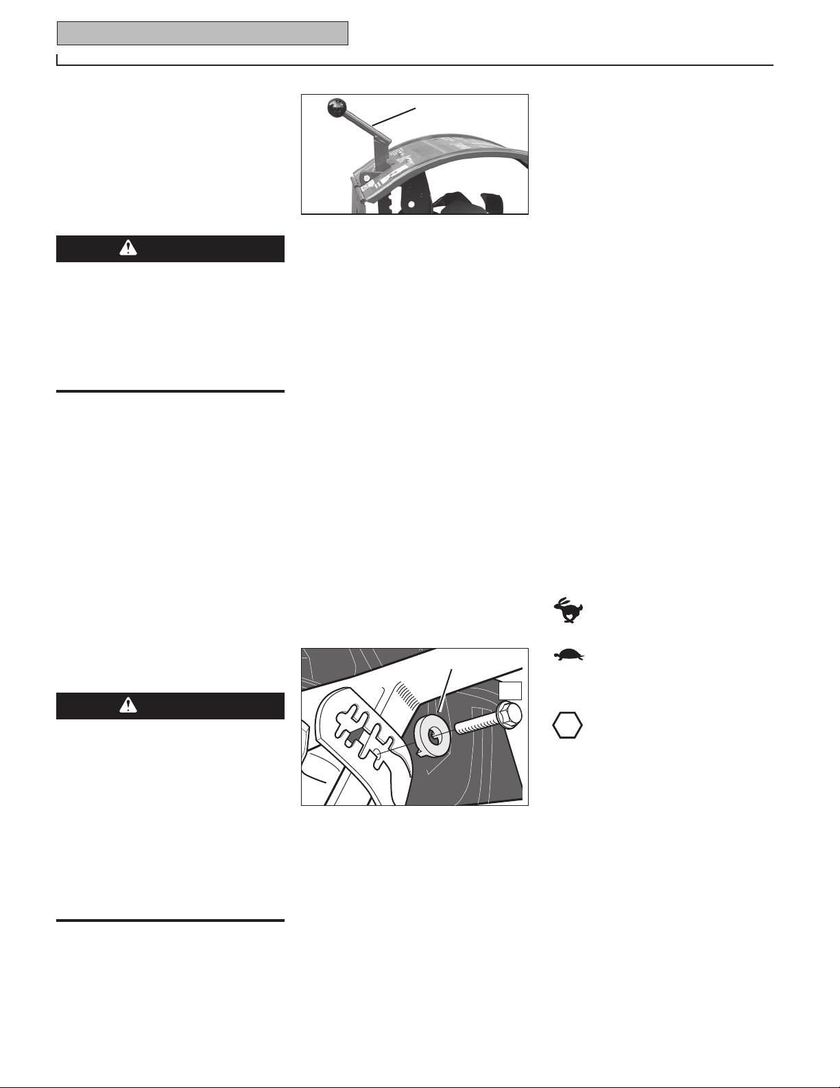
D
Figure 3-2: Depth Regulator Lever.
The highest notch (lever all the way down)
raises the tines approximately
1-1/2 inches off the ground. This “travel”
position allows the tiller to be moved
without the tines digging into the ground.
Moving the lever up increases the tilling
depth. The lowest notch allows a tilling
depth of approximately six to eight inches,
depending on soil conditions.
For best results, always begin tilling at
a very shallow depth setting and gradually increase the tilling depth. Complete
details on using the Depth Regulator are
found in the “Operation” Section of this
manual.
HANDLEBAR HEIGHT ADJUSTMENT
The handlebar height is adjustable to
four different settings. Set the handlebar
height to a comfortable setting, but keep
in mind that the handlebars will be lower
when the tines are engaged in the soil.
To Adjust the Handlebar Height:
F
E
keyed washer into the slot. Tighten the
height adjustment screw securely.
5. Retighten the two screws at the ends
of the handlebar.
ENGINE CONTROLS
Refer to the engine manufacturer’s Engine
Owner’s Manual (included in the tiller
literature package) to identify the controls
on your engine. The following two controls are used when stopping or starting
the engine.
IMPORTANT:
the recoil start engine is located on the
engine.
ENGINE THROTTLE CONTROL LEVER
The Engine Throttle Control Lever (located
on engine--see Figure 4-1) is used to
regulate the engine speed. On the recoil
start model only, it is also used to stop
the engine (on the electric start model, the
electric start keyswitch is used to stop the
engine). The throttle settings are shown
below.
IMPORTANT:
the Engine” in the “Operation” Section
for detailed engine starting and stopping
instructions.
The control for stopping
See “Starting and Stopping
FAST - Use for most tilling and
cultivating projects.
- Use when idling engine
SLOW
or when slower tilling and cultivating speeds are needed.
• Do not attempt to till too deeply too
quickly. Gradually work down to deeper
tilling depths.
• Place the Depth Regulator Lever in
the “travel” position before starting
the engine. This position prevents the
tines from touching the ground until
you are ready to begin tilling.
Failure to follow this warning could
result in personal injury or property
damage.
DEPTH REGULATOR
The Depth Regulator lever (D, Figure 3-2)
controls the tilling depth of the tines. Pull
the lever straight back and slide it up or
down to engage the notched height settings.
www.mymowerparts.com
www.mymowerparts.com
Figure 3-3: Handlebar height adjustment.
1. Stop the engine, wait for all parts to
stop moving and then disconnect the
spark plug wire. Remove the ignition key
on electric start models.
2. Loosen the two screws at the lower
ends of the handlebar.
3. Loosen the height adjustment screw
(E, Figure 3-3) and pull the keyed washer
(F) free of the slots in the curved height
adjustment bracket.
4. Move the handlebars to the new slot
setting and insert the raised keys on the
- Stops the engine (on
STOP
recoil start models only).
ELECTRIC START KEYSWITCH
(MODEL E663E)
The ignition keyswitch on the electric
start model is used to start and stop
the engine. The keyswitch settings are
described below.
IMPORTANT:
the Engine” in the “Operation” Section for
detailed instructions.
OFF - Stops engine.
RUN - After starting, key returns to run
position.
START - Starts engine. Release key when
engine starts (avoid cranking engine for
longer than 15 seconds for each attempt).
See “Starting and Stopping
WARNING
DANGER
CAUTION
For Parts Call 606-678-9623 or 606-561-4983
For Parts Call 606-678-9623 or 606-561-4983
Section
11
Before operating your machine, carefully read and understand all safety
(Section 1), controls (Section 3) and
operating instructions (Section 4) in
this Manual, in the separate Engine
Owner’s Manual, and on the decals on
the machine.
Failure to follow these instructions can
result in serious personal injury.
INTRODUCTION
Read this Section of the manual thoroughly before you start the engine. Then,
take the time to familiarize yourself with
the basic operation of the tiller before
using it in the garden.
Find an open, level area and practice
using the tiller controls without the tines
engaging the soil (put tines in “travel”
setting). Only after you’ve become completely familiar with the tiller should you
begin using it in the garden.
BREAK-IN OPERATION
Perform the following maintenance after
the first two hours of new operation (see
“Maintenance” in this manual and the
Engine Owner’s Manual).
1. Change engine oil.
2. Check for loose or missing hardware
on unit. Tighten or replace as needed.
3. Check transmission gear oil level.
4. Check tension on forward clutch belt.
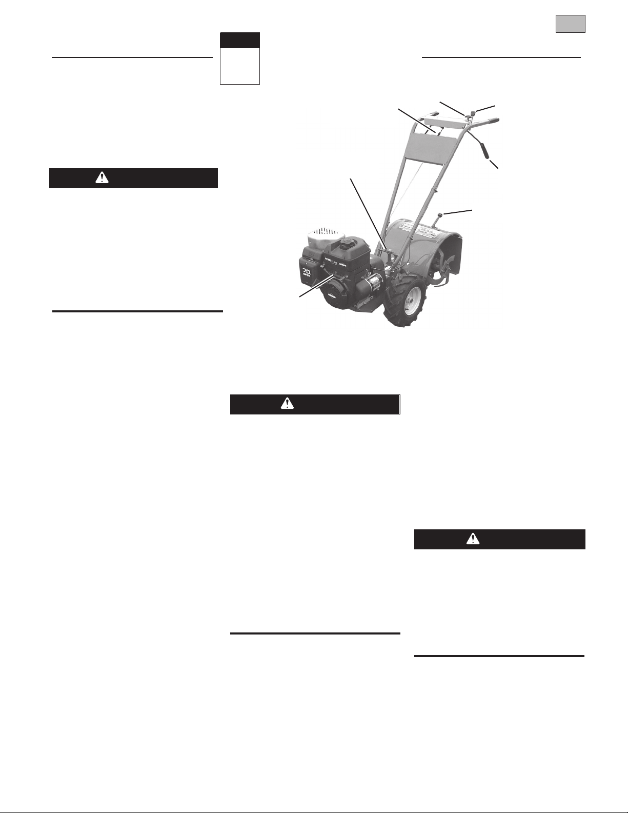
4
Engine Throttle
Control Lever
Operation
Forward Clutch
Control Lever
Handlebar Height
Adjustment Screw
Figure 4-1: Location of main tiller controls.
STARTING AND STOPPING
THE ENGINE
To help prevent serious personal injury
or damage to equipment:
• Before starting engine, put Wheel Gear
Lever in ENGAGE position.
• Before starting engine, put Forward
Clutch Control levers and Reverse
Clutch Control in neutral (disengaged)
positions by releasing controls.
• Ne v e r run engine in d o o rs or in
enclosed, poorly ventilated areas.
Engine exhaust contains carbon monoxide, an odorless and deadly gas.
• Avoi d e ngine muff ler and nearb y
areas. Temperatures in these areas
may exceed 150oF.
Reverse Clutch
Control
1. Read Sections 1 and 3 in this Manual.
Read the separate Engine Owner’s
Manual.
2. Check unit for loose or missing hardware. Service as required.
3. Check engine oil level. See Engine
Owner’s Manual.
4. Check that all safety guards and
covers are in place.
5. Check air cleaner and engine cooling
system. See Engine Owner’s Manual.
6. Attach spark plug wire to spark plug.
GASOLINE IS HIGHLY FLAMMABLE AND
ITS VAPORS ARE EXPLOSIVE.
Follow gasoline safety rules in this
manual (see Section 1) and in the separate Engine Owner’s Manual.
Failure to follow gasoline safety instructions can result in serious personal
injury and property damage.
Wheel Gear Lever
Forward Clutch
Control Lever
Depth Regulator Lever
PRE-START CHECKLIST:
Make the following checks and perform
the following services before starting the
engine.
www.mymowerparts.com
www.mymowerparts.com
7. Fill the fuel tank with gasoline according to the directions in the separate
Engine Owner’s Manual. Follow all
instructions and safety rules carefully.

WARNING
WARNING
For Parts Call 606-678-9623 or 606-561-4983
For Parts Call 606-678-9623 or 606-561-4983
12 Section 4: Operation
STARTING THE ENGINE
The following steps describe how to start
and stop the engine. Do not attempt to
engage the tines or wheels until you
have read all of the operating instructions in this Section. Also review
the safety rules in Section 1: “Safety”
and the tiller and engine controls
information in Section 3: “Features and
Controls.”
1. Complete the “Pre-Start Checklist” on
the previous page.
2. Put the Wheel Gear Lever (Figure 4-1)
in the ENGAGE position.
3. Put the Depth Regulator Lever in the
“travel” position (lever all the way down)
so that the tines are clear of the ground.
4. Release all controls on the tiller.
5. Put the Engine Throttle Control Lever
(Figure 4-1) in the “FAST” setting.
6. On engines equipped with a fuel valve,
turn valve to open position as instructed
in the separate engine manual.
7. Choke or prime engine as instructed in
the separate Engine Owner’s Manual.
8. For recoil (non-electric) starting
models:
(a) Place one hand on fuel tank to sta-
bilize unit when you pull the starter
handle.
(b) Use the recoil starter rope to start
the engine as instructed in the
separate Engine Owner’s Manual.
When the engine starts, gradually
move the choke lever (on engines
so equipped) to the “NO CHOKE”,
“CHOKE OFF” or “RUN” position.
(c) Leave
9. For electric starting models (E663E):
(a) Turn the engine ignition key to
the Engine Throttle Control
Lever in the “FAST” setting.
the “START” setting and allow the
starter motor to crank the engine for
several seconds. Avoid cranking the
engine longer than 15 seconds at a
time as doing so could damage the
starter motor. NOTE: Refer to the
Engine Owner’s Manual for detailed
starting instructions.
(b) When the engine starts, release the
key and it will return to the “RUN”
setting.
(c) Gradually move choke lever
(on engines so equipped) to
“NO CHOKE”, “CHOKE OFF” or
“RUN” position.
(d) Leave the Engine Throttle Control
Lever in the “FAST” setting.
To Start the Electric Start Engine With
the Recoil Starter Rope
If necessary, the electric start engine can
be started with the recoil starter rope by
following the steps below:
1. If the battery is not “dead” or
damaged, leave it connected to the tiller
so it will be recharged during engine
operation. Make sure the battery cells
are filled to the UPPER LEVEL line with
electrolyte.
2. If the battery is “dead” or damaged,
remove it (refer to “Battery Removal and
Installation” in Section 5) and have it
tested. Before starting engine, cover the
terminal on the loose end of the positive (+) cable with the insulated boot and
secure it in place with electrical tape to
prevent electrical sparks.
3. Put the ignition key in the “RUN”
position and then follow Steps 1-8 of
“Starting the Engine.”
STOPPING THE ENGINE
1. To stop the wheels and tines, release
the Forward Clutch Control levers or the
Reverse Clutch Control knob (whichever
control is engaged).
2. To stop the engine on the recoil start
model, move the Engine Throttle Control
Lever to the “STOP” position.
3. To stop the engine on an electric start
model, move the ignition key to “OFF”.
IMPORTANT:
start engine, remove the ignition key from
the switch to reduce the possibility of
unauthorized starting of the engine.
After stopping an electric
OPERATING THE TILLER
The following pages provide guidelines to
using your tiller effectively and safely in
various gardening applications. Be sure
to read “Tilling Tips & Techniques” in this
Section before you actually put the tines
into the soil.
This is a traditional “standard rotating
tine” tiller with forward rotating tines. It
operates completely differently from CRT
(Counter Rotating Tines) tillers or from
low-cost front tine tillers.
1. Follow the “Pre-Start Checklist” on the
previous page. Be sure that the Wheel
Gear Lever is in the ENGAGE position.
2. Put the Depth Regulator Lever in the
“travel” position (lever all the way down)
so that the tines are clear of the ground.
Use this position when practicing with
your tiller or when moving to or from the
garden. When you are ready to begin
tilling, you must move the Depth Regulator Lever to the desired depth setting (see
“Tilling Tips & Techniques”).
3. Start the engine and allow it to warm
up. When warm, put Engine Throttle
Control Lever in “FAST” speed setting.
Keep away from rotating tines.
Rotating tines will cause injury.
4. For forward motion of the wheels and
tines:
(a) Pull one or both of the Forward
Clutch Control Levers up and hold
them against the handlebars. To
stop forward motion of the wheels
and tines, release the levers.
www.mymowerparts.com
www.mymowerparts.com
 Loading...