

Page 1
Safety • Assembly • Operation • Tips & Techniques • Maintenance • Troubleshooting • Parts Lists • Warranty
A O A AL
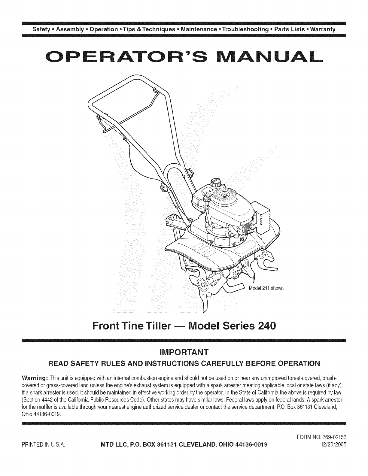
Model241shown
Front Tine Tiller -- Model Series 240
IMPORTANT
READ SAFETY RULES AND INSTRUCTIONS CAREFULLY BEFORE OPERATION
Warning: Thisunit isequippedwithaninternalcombustionengineandshouldnot beusedonornearanyunimprovedforest-covered,brush-
coveredor grass-coveredlandunlesstheengine'sexhaustsystemisequippedwitha sparkarrestermeetingapplicablelocalorstatelaws(if any).
If a sparkarresterisused,it shouldbemaintainedineffectiveworkingorderbytheoperator.IntheStateofCaliforniatheaboveisrequiredbylaw
(Section4442oftheCaliforniaPublicResourcesCode).Otherstatesmayhavesimilarlaws.Federallawsapplyonfederallands.Asparkarrester
forthe mufflerisavailablethroughyournearestengineauthorizedservicedealeror contacttheservicedepartment,RO.Box361131Cleveland,
Ohio44136-0019.
FORMNO.769-02153
PRINTEDIN U.S.A.
MTD LLC, P.O. BOX 361131 CLEVELAND, OHIO 44136-0019
12/20/2005
Page 2

This Operator's Manual is an important part of your new tiller, it will help you assemble,
prepare, and maintain the unit for best performance. Please read and understand what it says.
Table of Contents
Safety Labels ...................................................... 3
Safety ................................................................... 4
Assembly ............................................................. 6
Operation ............................................................. 8
Adjustments ...................................................... 12
Finding and Recording Model Number
BEFOREYOU ASSEMBLINGYOUR NEW EQUIPMENT,
please locatethe modelplate onthe equipmentandcopythe
informationtothe sample model plate provided tothe right.
Youcan locatethe modelplateby looking at the rear of the
tineshield.This informationis importantfor usewhen visiting
the manufacturer'sweb site,obtainingassistance from the
CustomerSupportDepartment,orwhencommunicatingwith
an authorizedservice dealer.
Maintenance ...................................................... 13
Troubleshooting ................................................ 14
Off-Season Storage .......................................... 15
Parts List ........................................................... 16
Warranty ............................................ Back Cover
f
Model Number
www.mtdproducts.com
Serial Number
MTD LLC
P.O. BOX 361131
CLEVELAND, OH 44136
330=220=4683
800-800-731 0
Customer Support
Please do IVOTretum the unit to the retailer from which it was
purchased, without first contacting Customer Support.
Ifyou have difficultyassemblingthis productorhave anyquestions regardingthe controls, operation,or maintenanceof this
unit,youcanseek helpfromthe experts.Choosefrom the options below:
• Visit www.mtdproducts.com. Click on the Service & Supportmenuoption.
• Phonea Customer Support Representative at 1-800-800-7310.
• The engine manufacturer is responsiblefor all engine-relatedissueswith regardsto performance, power-rating,specifica-
tions,warranty and service. Pleasereferto the engine manufacturer'sOwner's/Operator's Manual,packedseparatelywith
your unit, for moreinformation.
MTD _er_afio_a_ Aw®_8Wi_mir_@_r®d_cf_ O¢_rCompa_y
Product Menu
S,'.::hr_,iceS ,::_Jpp,._rt
Produd: Registration
Coa_ad__J_ ?riwcy Porky
2
Page 3
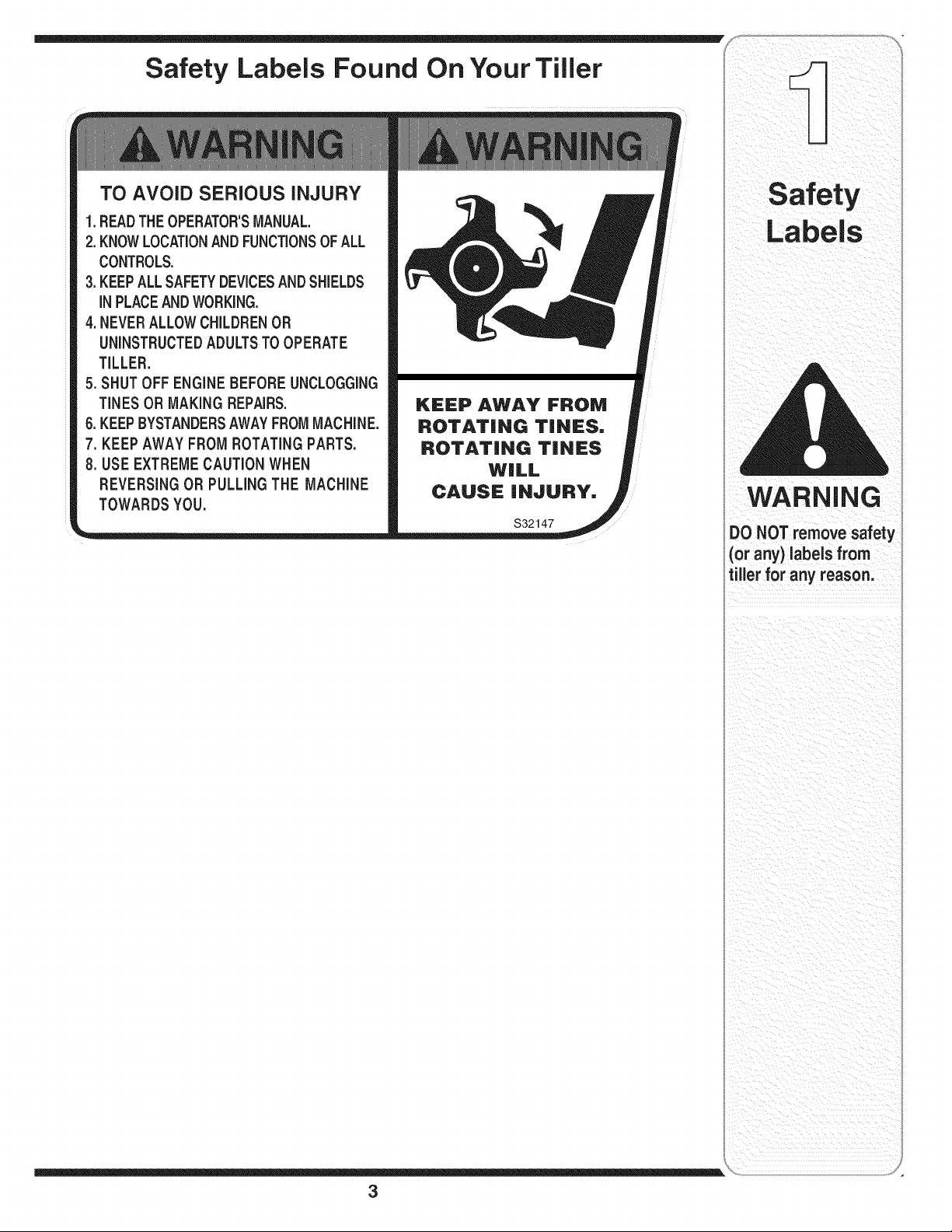
Safety Labels Found On Your Tiller
TO AVOID SERIOUS iNJURY
i_ii__iii_iI i__ii_
1.READTHEOPERATOR'SMANUAL.
2.KNOWLOCATIONANDFUNCTIONSOFALL
CONTROLS.
3.KEEPALLSAFETYDEVICESANDSHIELDS
iNPLACEANDWORKING.
4.NEVERALLOWCHILDRENOR
UNINSTRUCTEDADULTSTOOPERATE
TILLER.
5. SHUT OFF ENGINE BEFOREUNCLOGGING
TINES OR MAKING REPAIRS.
6.KEEPBYSTANDERSAWAYFROMMACHINE.
7,KEEP AWAY FROM ROTATING PARTS.
8.USE EXTREME CAUTION WHEN
REVERSING OR PULLING THE MACHINE
TOWARDS YOU.
Labels
WARNING
S32147
DONOT remove safety
(or any) labels from
tiller for any reason.
3
Page 4
Operat on
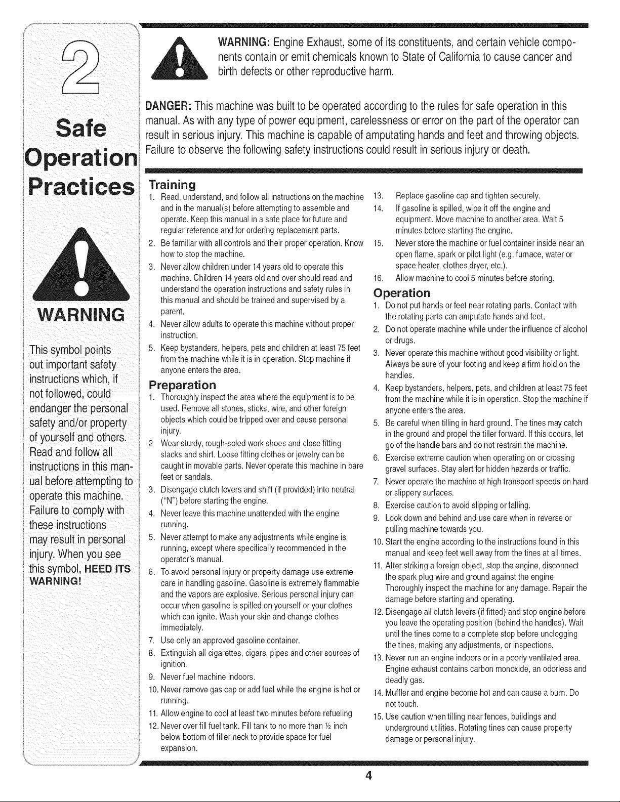
WARNING
Thissymbol points
outimportant safety
instructionswhich, if
notfollowed,could
endangerthe personal
safetyand/or property
of yourself and others.
Readand follow all
instructionsinthis man-
ualbeforeattempting to
operatethis machine.
Failureto complywith
these instructions
mayresult in personal
injury.When you see
i this symbol, HEED ITS
WARNING!
WARNING: EngineExhaust,some of its constituents, andcertain vehicle compo-
nentscontain or emit chemicals knownto Stateof Californiato cause cancer and
birth defects or other reproductiveharm.
DANGER: This machinewas built to beoperatedaccording to the rulesforsafe operationin this
manual.As with any type of powerequipment,carelessness or error on the part ofthe operatorcan
result in seriousinjury.This machine is capable of amputatinghands andfeet andthrowing objects.
Failureto observethe followingsafety instructionscould resultinserious injury ordeath.
Training
1. Read,understand,andfollow all instructionsonthemachine
andinthe manual(s)beforeattemptingto assembleand
operate.Keepthismanualina safeplaceforfutureand
regularreferenceand fororderingreplacementparts.
2. Befamiliarwithall controlsand theirproperoperation.Know
howtostopthe machine.
3. Neverallowchildrenunder14yearsoldto operatethis
machine.Children14yearsold andovershouldreadand
understandthe operationinstructionsand safetyrules in
this manualandshouldbe trainedand supervisedby a
parent.
4. Neverallowadultsto operatethis machinewithoutproper
instruction.
5. Keepbystanders,helpers,petsandchildrenatleast75feet
fromthe machinewhileitis inoperation.Stopmachineif
anyoneentersthearea.
Preparation
1. Thoroughlyinspectthe areawheretheequipmentisto be
used.Removeallstones,sticks,wire, andotherforeign
objectswhichcouldbetrippedoverandcausepersonal
injury.
2 Wearsturdy,rough-soledworkshoesand closefitting
slacksandshirt.Loosefittingclothesor jewelrycan be
caughtin movableparts.Neveroperatethis machinein bare
feetorsandals.
3. Disengageclutchleversand shift(if provided)intoneutral
("N")beforestartingthe engine.
4. Neverleavethis machineunattendedwiththe engine
running.
5. Neverattemptto makeanyadjustmentswhile engineis
running,exceptwherespecificallyrecommendedinthe
operator'smanual.
6. Toavoid personalinjury orpropertydamageuseextreme
carein handlinggasoline.Gasolineis extremelyflammable
andthevaporsare explosive.Seriouspersonalinjurycan
occurwhengasolineisspilledonyourselforyourclothes
whichcanignite.Washyourskin andchangeclothes
immediately.
7. Useonly anapprovedgasolinecontainer.
8. Extinguishallcigarettes,cigars,pipesand othersourcesof
ignition.
9. Neverfuelmachineindoors.
10.Neverremovegascapor addfuel whiletheengineishot or
running.
11.Allowenginetocool at leasttwo minutesbeforerefueling
12.Neveroverfillfueltank.Filltankto nomorethanY2inch
belowbottomof fillerneckto providespacefor fuel
expansion.
13. Replacegasolinecapandtightensecurely.
14. Ifgasolineisspilled,wipeit offtheengineand
equipment.Movemachinetoanotherarea.Wait5
minutesbeforestartingthe engine.
15. Neverstorethe machineorfuelcontainerinside nearan
openflame,spark or pilotlight(e.g.furnace,wateror
spaceheater,clothesdryer,etc.).
16. Allowmachineto cool 5minutesbeforestoring.
Operation
1. Do notput handsor feetnear rotatingparts.Contactwith
the rotatingpartscanamputatehandsandfeet.
2. Do notoperatemachinewhileunderthe influenceofalcohol
or drugs.
3. Neveroperatethismachinewithoutgoodvisibility orlight.
Alwaysbe sureof yourfootingand keepafirm hold onthe
handles.
4. Keepbystanders,helpers,pets,and childrenat least75feet
fromthe machinewhileitis inoperation.Stopthe machineif
anyoneentersthearea.
5. Becarefulwhentillingin hardground.Thetines maycatch
in thegroundandpropelthe tillerforward. Ifthis occurs,let
goof the handlebars anddo notrestrainthe machine.
6. Exerciseextremecautionwhenoperatingonor crossing
gravelsurfaces.Stayalertfor hiddenhazardsor traffic.
7. Neveroperatethe machineat hightransportspeedson hard
or slipperysurfaces.
8. Exercisecautionto avoidslippingorfalling.
9. Lookdownand behindandusecarewhenin reverseor
pullingmachinetowardsyou.
10.Startthe engineaccordingtotheinstructionsfoundin this
manualandkeepfeet wellawayfromthetinesat alltimes.
11.Afterstrikingaforeignobject,stoptheengine,disconnect
the sparkplugwireandgroundagainstthe engine
Thoroughlyinspectthe machinefor anydamage.Repairthe
damagebeforestarting andoperating.
12.Disengageallclutchlevers(if fitted)andstopenginebefore
youleavetheoperatingposition(behindthe handles).Wait
untilthetinescometoa completestopbeforeunclogging
thetines, makinganyadjustments,orinspections.
13.Neverrun anengineindoorsor inapoorlyventilatedarea.
Engineexhaustcontainscarbonmonoxide,an odorlessand
deadlygas.
14.Mufflerand enginebecomehotandcancausea burn.Do
nottouch.
15.Usecautionwhentillingnearfences,buildingsand
undergroundutilities.Rotatingtinescancauseproperty
damageor personalinjury.
4
Page 5
16.Donotoverloadmachinecapacityby attemptingtotill soilto
deepattoofast of arate.
17.Ifthe machineshouldstartmakinganunusualnoiseor
vibration,stopthe engine,disconnectthe sparkplugwire
andgroundit againstthe engine.Inspectthoroughlyfor
damage.Repairanydamagebeforestartingandoperating.
18.Keepallshields,guards,andsafetydevicesin placeand
operatingproperly.
19.Neverpick upor carrymachinewhiletheengineis running.
20.Use onlyattachmentsandaccessoriesapprovedbythe
manufacturer.Failuretodoso can resultinpersonalinjury.
21. Ifsituationsoccur whichare notcoveredinthis manual,use
careandgoodjudgment.Contactyourdealerortelephone
1-800-800-7310forassistanceandthe nameof your
nearestservicingdealer.
Maintenance & Storage
1. Nevertamperwith safetydevices.Checktheirproper
operationregularly.
2. Checkboltsandscrewsfor propertightnessatfrequent
intervalsto keepthe machineinsafe workingcondition.
Also,visuallyinspectmachineforany damage.
3. Beforecleaning,repairing,orinspecting,stopthe engine
andmakecertainthe tinesand all movingpartshave
stopped.Disconnectthesparkplugwireandgroundit
againstthe engineto preventunintendedstarting.
4. Do notchangethe enginegovernorsettings orover-speed
the engine.Thegovernorcontrolsthe maximumsafe
operatingspeedofthe engine.
5. Maintainor replacesafetyand instructionlabels,as
necessary.
6. Followthismanualfor safeloading,unloading,transporting,
andstorageofthis machine.
7. Neverstorethemachineor fuelcontainerinsidewhere
there isanopenflame,sparkorpilotlightsuchas awater
heater,furnace,clothesdryer,etc.
8. Alwaysrefertothe operator'smanualfor properinstructions
on off-seasonstorage.
9. Ifthe fueltank hasto bedrained,dothis outdoors.
10.Observeproperdisposallawsand regulationsforgas,oil,
etc.to protectthe environment.
Your Responsibility
1. Restrictthe useofthispowermachineto personswhoread,
understand,andfollowthe warningsandinstructionsinthis
manualandonthemachine.
2. Thesafetylabelsonthetillerareshowninthe "Safety
Labels"section.Toensuresafeoperationofthe tiller,follow
theinstructionsonalllabelsclosely.
ces
WARNING
Thissymbol points
out importantsafety
instructionswhich, if
notfollowed,could
endangerthe personal
safety and/or property
ofyourselfand others.
Readandfollowall
instructions inthisman-
ual before attemptingto
operatethis machine.
Failureto complywith
these instructions
mayresult in personal
njury.Whenyou see
this symbol, HEED ITS
WARNING!
5
Page 6
NOTE: Stand behind
the tilleras if you were
goingto operate it. Your
righthand corresponds
to the right sideof the
tiller; your left hand
correspondsto the left
sideof the tiller.
NOTE:This operator's
manualmay cover
various modelsof tillers.
The unitsillustrated
mayvary slightlyfrom
your unit. Followonly
those instructionswhich
pertainto your model
number.
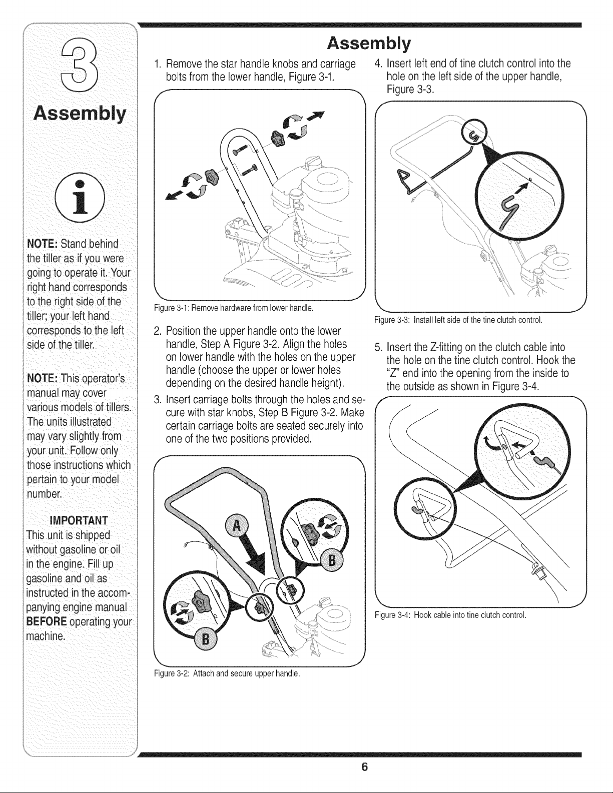
Assembly
1. Removethe star handle knobs andcarriage
boltsfrom the lowerhandle, Figure3-1.
J
Figure3-1:Removehardwarefrom lowerhandle.
2. Positionthe upper handleontothe lower
handle,Step A Figure3-2.Alignthe holes
onlowerhandlewith the holes on the upper
handle(choosethe upper or lower holes
dependingon the desired handleheight).
3. Insertcarriage boltsthroughtheholesand se-
cure with star knobs,Step B Figure 3-2. Make
certain carriageboltsare seated securely into
one ofthetwo positions provided.
f
4. Insert leftendof tine clutch control into the
holeon the leftside of the upper handle,
Figure3-3.
f
\
J
Figure3-3: Installleftsideofthe tineclutchcontrol.
5. InserttheZ-fittingon the clutch cable into
the hole on the tine clutch control. Hook the
"Z" end into the opening from the insideto
theoutside as shown in Figure3-4.
iMPORTANT
::Thisunit is shipped
without gasoline or oi
iinthe engine. Fillup
igasolineand oil as
instructedintheaccom-
panyingenginemanual
iBEFOREoperatingyour
machine.
'_ _j
Figure3-2:Attachandsecureupperhandle.
....... J
Figure3-4: Hookcableintotineclutchcontrol.
6
\
Page 7

6.Squeezethetineclutchcontrolinward.
Insertrightendintotheholeontherightside
oftheupperhandle,Figure3-5.
f
,,_ .y
Figure3-5: Installrightend oftineclutchcontrol.
NOTE: Stand behind
thetiller as if you were
goingto operate it. Your
ighthand corresponds
to the rightside ofthe
tiller; your left hand
correspondstothe left
side of the tiller.
NOTE: This operator's
manualmay cover
various modelsoftillers.
The units illustrated
mayvary slightlyfrom
our unit. Followonly
those instructionswhich
)ertain to your mode[
number.
7
Page 8

You rTiller
WARNING
Thetine clutch control
isasafetydevice.
Neverattempt to
bypass its operation.
Rec0il
Starter
Clutch Cable
Rear Wheel
with Depth
Stake
Useextremecare
when handling
gasoline.Gasoline is
extremely flammable
and the vapors are
explosive.Neverfuel
the machine indoors
i orwhilethe engine
ishot or running.
Extinguishcigarettes,
cigars, pipes, and
other sources of
ignition.
Keephandsand feet
awayfrom the tines.
Referto warning label
on the unit.
Figure4-1:The majorpartsofthetiller (model241shown).
_ ARNING:Read,understand, and
follow ail instructionsandwarnings
postedonthe machine and inthis
manualbefore operating.
Tine Clutch Control
Theclutchcontrolleverislocatedontheupperhandle.
Squeezingthe leveragainstthe handleengagesthefine
drive.Releasetheleverto stopthe tinesfromturning.
Rear Wheel with Depth Stake
Thedepthstakeandwheelare locatedatthe rearof
thetiller.Bothmaybeadjusted.Refertothe "Wheel
Position"and"DepthStake"sectionsfor instructions.
Handle Knobs
Thehandleheightmaybeadjusted.Loosentheknobs
andremovethecarriageboltstochangetheposition.
Reinstallandtightenthe hardwarewhencomplete.
Engine Controls
NOTE:Seetheseparateenginemanualforadditional
engineinformationand functions.
Throttle Control
Thethrottlecontrolleveris locatedon theengine,it
controlstheengine'sspeedandstopstheengine.
* Withthe throttlecontrolmovedcompletelyto theleft,
thecarburetorisin STARTor FASTposition.Use
maximumenginespeedfor deeptilling.
* Movethe throttlecontrollevertotherightto reduce
enginespeed.ThrottlecontrolshouldbeatIDLEfor
transportingthe tiller.
Movethethrottleallthewaytothe rightto stopthe
engine.
Primer
Theprimer,locatedonthe engine,is usedto pumpgas
intothe carburetorandaid instartingthe engine.Useit
tostarta coldengine,butdonotuseitto restartawarm
engineaftera shortshutdown.
Recoil Starter
Therecoilstarteris locatedon theengineandisusedto
manuallystartthe engine.
8
Page 9

_ ARNING:Read,understand,and
follow all instructionsandwarnings
postedonthe machine and in this
manualbefore operating.
manyotherusefullaborsavingtasksinthe garden.After
engineis runningandappropriatespeedseton throttle,
squeezefineclutchcontrol(seeFigure4-1)against
upperhandleto engagethefinedrive.Releasethelever
tostopthetinesfromturning.
Before Starting
Gas And Oil Fill-Up
Servicetheenginewithgasolineandoil asinstructedin
theseparateenginemanualpackedwithyourtiller.Read
instructionscarefully.
_._|1_ ARNING:Useextremecarewhen
handlinggasoline. Gasolineisex-
tremely flammable and thevaporsare
explosive.Neverfuel machine indoors
or while the engineishot or running.
Starting Engine
_ WARNING:Besureno one is standing
1. Attachsparkplugwireto sparkplug. Makesurethe
metalcapontheendofthesparkplugisfastened
securelyoverthemetaltip on thesparkplug.
2. Makesurethatthefineclutchcontrolisdisengaged.
3. PlacethethrottlecontrolintheFASTposition.
4. Forfirsttimestart-up,firmlypressengineprimerfive
(5)times.Forallfuturestarts,pressthree(3) times.
Waitabouttwo secondsbetweeneachpress.
5. Placelefthandongas tank.Grasprecoilstarterand
pullropeoutslowlyuntilenginereachesthebeginning
ofitscompressioncycle(ropewillpull slightlyharder
atthispoint).
6. Pullropewitharapid,continuous,fullarmstroke.
Keepa firmgripon handle.Letroperewindslowly.Do
notlet recoilstartersnapbackagainstengine.Repeat
untilenginestarts.
infront of the tiller while the engineis
runningor being started.
Wheel Position
Thetiller isshippedwiththewheeladjustedsuchthat the
unitsitslevel.Beforetilling,thewheelmustberaised.To
dothis,removethe clevisandcotterpins,raisethewheel
tothe desiredposition,thenreattachpinsto secure,
Figure4-2.Fortransportingthetiller,reversethestepsto
lowerthewheel.
Figure4-2:WheelAdjustment
Depth Stake
Thedepth stakeactsasabrakeforthetillerandcontrols
thedepthand speedat whichthemachinewilloperate,
Figure4-3. Removethe clevisandcotterpins,raiseor
lowerthedepthstake,thenreattachpinstosecure.
Your Tiller
WARNING
Besorenooneother
thanthe operator :is
standing near the tiller
while starting engine
or operating the unit.
Never run engine
indoorsor in enclosed,
poorly ventilated
areas. Engine exhaust
contains carbon
monoxide, an odorless
and deadly
hands, feet, hair and
loose clothing away
fromanymo. ngparts
Stopping Engine
1. MovethrottlecontrollevertoSTOPor OFFposition.
2. Disconnectsparkplugwirefromsparkplugand
groundagainsttheengine.
Using Your Tiller
Yourtiller(alsoknownasacultivator)isa precisionbuilt
machinedesignedforseedbedpreparation,cultivating,
furrowing,andmulching.It isengineeredto minimize
thehardestworkinthevegetableor flowergarden,to
till thesoilforplantingandcultivating,andto perform
See your engine
manual packaged with
your unit for detailed
instructions pertaining
to starting the engine,
Figure4-3:The DepthStake
_ii_i_;i/;I_I:_I_I_I_I_I_I_I_I_I_I_I_I!!il
9
Page 10

i ¸
Fortilling,thedepthstakemustbeloweredandthe
wheelmustbe raised,Figure4-4.
Byincreasingthedepthof thedepthstake,theforward
speedof themachineis reducedandthe workingdepth
isincreased.Whenthe depthstakeis raised,theworking
depthof themachineis reducedandthe forwardspeed
isincreased.Theworkingdepthofthemachinemay
bepredeterminedbysettingthedepthstakesothatthe
wheelsareaboutfourinchesfromthegroundwhenthe
tinesanddepthstakearerestingonthe ground.This
settingwill permitaworkingdepthof aboutfourinches.
Whenpresettingtheworkingdepth,the handlesshould
beadjustedsothehandgripsarea littleabovewaist.
Thetiller willbelowerwhenthe tinesand depthstake
penetratetheground.
Figure4-4:Lowerthedepthstakeandraisethe wheelwhen
tilling.
Controlling Speed and Tilling Depth
Whentilling,leaveapproximately8 inchesof untilledsoil
betweenthefirst andsecondtillingpaths,thenmake
thethirdpathbetweenthefirstandsecond,Figure4-5.
Insomesoils,thedesireddepthis obtainedthefirst
timeoverthe garden.Inothersoils,thedesireddepth
isobtainedbygoingoverthegardentwoorthreetimes.
Passesshouldbemadeacrossthelengthandwidth
ofthe gardenalternately.Rockswhichareturnedup
shouldberemovedfromthe gardenarea.
J
Figure4-5:Recommendedtillerpaths.
Thetypeof soilandworkingconditionswilldeterminethe
actualsettingof thedepthstakeandthehandlepressure
required.
Cultivating
Forcultivating,a twotothreeinchdepth isdesirable.The
throttleshouldbe settocontrolforwardmovementto a
slowwalkingspeed.Withtheoutertinesinstalled,the
workingwidthofthe machineis22 or24inches.
Forcultivation,thismaybereducedto 13inchesby
removingtheoutertines,refertotheAdjustmentSection.
Whenlayingoutplant rows,besuretoallowenough
widthto permitcultivationbetweentherows.Ingrowing
cornor similarcrops,check-rowplantingwillpermitcross
cultivationandpracticallyeliminatehandhoeing,Figure
4-6.
Handle Pressure
Furthercontroloftillingdepthandtravelspeedcanbe
obtainedbyvariationofpressureonthe handles.
A downwardpressureon thehandleswillreducethe
workingdepthandincreasetheforwardspeed.An
upwardpressureon the handleswillincreasethe
workingdepthandreducetheforwardspeed.
Figure4-6:Allowenoughareabetweenrows.
Thetiller hasmanyusesotherthantillingandcultivating
a garden.Oneof theseisthepreparationoflawnarea
forseeding.Thetillerwillprepareadeepseedbedwhich
10
Page 11

willbefreeofharduntilledspots,allowingabetterstandofgrassto grow.Thetillerisveryusefulforlooseninghard
soilfor excavationwitha shovel;Notedioushandworkwillbenecessary.Yourtillermaybe usedformixingcompost
in thepileorfor mixingitwiththesoil inyourgarden.Thisshouldbedoneafterthesoil hasbeenbrokentothefull
workingdepth.Thecompostshouldbe workedin toadepthofsix to seveninches.Thismaybedonebyworkingthe
lengthof thegardenandthenbymakingseparatepassesacrossits width.Theadditionofdecayedorganicmatterwill
substantiallyincreasethefertilityofyourgarden.Forproperdecayingaction,fertilizershouldbeappliedandworkedin
withthemulchmaterials.Breakingupleavesandstrawandmixingitwithseveralinchesof soilallowsproperaeration
ofthe plantrootsystemandretardsthe growthofweeds.
Transporting and Storing the Tiller
Totransportthetiller,lowerthewheeland movethe Tostorethe tiller,lowerthe wheelandorientthedepth
depthstaketothehighestposition,Figure4-7. stakeso botharetouchingthe ground,Figure4-8.
J _ J
Figure4-7:Fortransport,lowerwheelandraisedepthstake. Figure4-8:Forstorage,lowerwheelanddepthstake.
Your Tiller
Besurenooneother
than the operator is
standing near the tiller
while starting engine
or operating the unit;
Never engine
indoorsOrinenclosed,
poorlyventilated
areas. Engine exhaust
containscarbo
monoxide, anodorless
and deadly gas:Keep
hands, feet, hair and
looseclothingaway
from any moving parts
11
See your engine
manual packaged with
your unit for detailed
instructions pertaining
to starting the enginei
Page 12

Making Adjustments
i¸ : / i:!
NOTEi This operator,s
manual may coverVari_
ous modelsoftillerS:
The unts illuStrated
mayVaryslightlyfrom
your unit.Followon!y
those instructions
Whichpertain to your
model numberl ...........
Warning: Disconnectthe spark
plugwire and ground it against
the engine before performing
any adjustments.
Engine Adjustment
Referto the separateengine manualfor engine
adjustmentinstructions.
Tine Width Adjustment
The tilling width ofthe unit is22 inches.Tilling
width can increaseto 24 inchesby removing
the clevis and cotter pins, sliding each outer
tine out one inch, and securingin this position
with the pins. Forcultivation, reduce thetine
width to 13inches byremovingthe outer tines
completely,Figure 5-1.
f
,€ 24-inch
2-inch •
NOTE: Stand behind
thetiller as if you were
goingto operate it.
Yourrighthand cor-
respondsto the right
side of the tiller; your
left hand corresponds
:othe left side of the
:iller.
J
Figure5-1:Tinewidthadjustment.
12
Page 13

nect sparkplug,andgroundagainst
performingany maintenanceon your
machine.
Engine
Refertothe separateenginemanualforenginemainte-
nanceinstructions.
• Maintainengineoilas instructedintheseparate
enginemanualpackedwithyourunit.Readandfollow
instructionscarefully.
• Serviceair cleanereveryten hoursundernormal
conditions.Cleaneveryhourunderextremelydusty
conditions.Poorengineperformanceandflooding
usuallyindicatesthattheair cleanershouldbe
serviced.Toservicetheaircleaner,refertothe
separateenginemanualpackedwithyourunit.
'_,'_) MPORTANT:Neverrunyourenginewithout
air cleanercompletely assembled.
• Thesparkplugshouldbecleanedandthegap reset
every25hoursofengineoperation.Sparkplug
replacementis recommendedat thestartofeachtiller
season;checkenginemanualforcorrectplugtype
andgap specification.
• Cleantheengineregularlywitha clothor brush.
Keepthecoolingsystem(blowerhousingarea)clean
to permitproperaircirculationwhichisessentialto
engineperformanceand life.Becertainto removeall
dirtandcombustibledebrisfrommufflerarea.
Lubrication
Transmission
Thetransmissionispre-lubricatedandsealedatthefac-
tory.It requiresnochecking.Seean authorizedservice
dealerforany serviceissues.
Tine Shafts
Removetine assembliesand lubricatethetine shaftsat
leastoncea season.
Wheel Shaft
Removewheelassemblyandlubricatetheaxleshaftat
leastoncea season.
Yourtillerhas beenengineeredwitha beltmadeof
specialmaterialforlongerlifeand betterperformance.
It shouldnotbe replacedwithanoff-the-shelfbelt.See
theretailerfromwhichyoupurchasedyourtiller,an
authorizedMTDServiceDealer,orcall 1-800-800-7310
forinformationregardingpriceandavailability.
1. Removetheframeandenginebyremovingthesix
screwsandlocknutsholdingtheengineandframeto
theshield,Figure6-1.
Figure6-1:Removeengineandframetogainaccesstothebelt.
(Model241shown)
2. Loosenthelocknut showninStepAFigure6-2.
3. Unloopthebeltfromthepulleys,StepB Figure6-2.
4. Reassemblethe newbelt andtightenthelocknut.
5. Reattachframeandengineusingthehardware
removedearlier.
Alwaysstop engine,
disconnectspark
plugland ground
ga nstenginebefore
cleaningl lubricat-
mgor performing
maintenance on your
machine:
IMPORTANT:Never
usea pressurewasher
to clean yourtiller.
Water can penetrate
tightareas ofthetiller
causing serious damage
to the unit.
Cleaning Tine Area
Cleanthe undersideofthefineshieldaftereach use.
Thedirt washesoffthetineseasierifrinsedoff im-
mediatelyinsteadof afteritdries.Alwaystoweldrythe
tillerafterwardsandapplya lightcoatofoil or siliconeto
preventrustingorwaterdamage.
(]_,_j) IMPORTANT:Neveruse a "pressure washer"
to clean your tiller. Water can penetratetight
areasof the tiller causing serious damage.
IMPORTANT:Never run
your engine withoutthe
aircleaner completely
assembled.
Figure6-2:Loosenthenuttoremovethebelt.
13
Page 14

Problem Cause Remedy
Engine fa! s tOstart wi!ed ! connect wireto spa[k
I 2 Fue tankemptyorstaefue 2 F tankwthcean freshgaso ne
3. Throttle control!evernotincorrect 3, Movethrottlelevertostart position.
sta_ingPosition(i!equipped)position I
4, Chokenot n ON post on. 5: clean fuelline.
&Blocked fue! 6 C!ean:adjustgaROr[epiace:
Fau!tysPa[k wait afew rninutesto restartlbutdo
7, Engnefood ng. . not prme(f equpped)
For repairs beyond
the minor adjust.
merits listed here,
contact an authorized
service dealer.
Engineruns erratic
1. Sparkplugwireloose.
2. Unitrunningon CHOKE.
3. Blockedfuellineor stalefuel.
4. Ventplugged.
5. Waterordirtin fuelsystem.
6. Dirtyair cleaner.
7. Carburetorout ofadjustment.
1. Connectandtightenspark
plugwire.
2. MovechokelevertoOFE
3. Cleanfuelline;filltankwithclean,
freshgasoline.
4. Clearvent.
5. Drainfueltank. Refillwith
freshfuel.
6. Cleanfollowingenginemanual.
7. Referto enginemanual.
I
Engineoverheats !; Engineoi!!eve!low: 1; E!!crankcasew thProPeroi!:
2 Di!tYa[fi!ter: 2 c!eanai[C!eaiei:
Ai[f!ow iest[cte& Removeblowerhousingandc!eanr
4. Carburetornotadjustedproperly. 4. Referto enginemanual.
Tines do no engage
1. Foreignobjectlodgedintines.
2. Tineclevispin(s)missing.
3. Beltwornand/orstretched.
4. Pulleyandidlernotincorrectadjust-
ment.
1. Stop tillercompletely,checkand
discardforeignobject.
2. Replacefineclevispin(s).
3. Replacebelt.
4. Takeunit toauthorizedservice
14
Page 15

Off-Season Storage
ifthe tillerwill notbeusedforaperiodlongerthan30
days,the followingstepsshouldbetakentopreparethe
tillerfor storage.
Cleantheexteriorofengineandthe entiretiller
thoroughly.Lubricatethetillerasdescribedin the
lubricationinstructions.
Wedonotrecommendtheuseof pressurewashersto
cleanyour unit.Theymaycausedamageto spindles,
pulleys,bearings,orthe engine.Theuseofpressure
washerswill resultin shortenedlifeand reduce
serviceability.
Refertothe enginemanualforcorrectenginestorage
instructions.
Wipetineswithoiledragto preventrust.
Storetillerin aclean,dryarea.Donotstorenextto
corrosivematerials,suchas fertilizer.
Whenstoringanytypeofpowerequipmentinan
unventilatedor metalstorageshed,careshouldbe
takentorustprooftheequipment.Usinga lightoil
or silicone,coatthe equipmentandespeciallyany
springs,bearings,andcables.
NOTE: When storing
anytype of power
equipment inan unven-
tilatedor metalstorage
shed.careshould be
takento rustproofthe
equipment.Usinga
Ight oil or silicone,coat
theequipmentand
especiallyany springs,
bearings,and cables.
15
Page 16

16
Page 17

1 749-04282 UpperHandle
2 720-04072 StarHandle Knob
3 749-04281 LowerHandle
4 710-04398 FlangeScrew5/16-18x7.5
5 754-04123 Belt
6 756-04163 idlerPulley
7 748-04125 ShoulderSpacer
8 686-04080 IdlerBracket
9 712-04065 FlangeLockNut:3/8-16
10 710-0654A TT Screw3/8-16x 1.00
11 786-04303 Frame
Parts List
12 710-0514 HHCapScrew3/8-16x 1.00
13 732-0418 ExtensionSpring
14 738-04139 Stud33x 1.5x 3/8-16
15 756-04217 FlywheelPulley
16 710-0591 HHCapScrew3/8-24x 1.00
17 710-0520 HHCapScrew3/8-16x 1.50
18 786-04256 TineShield61cm
19 711-0415 ClevisPin
20 642-0005 OuterTineAssemblyLH
21 642-0003 InnerTineAssemblyLH
22 714-0149B internalCotterPin
23 710-0809 TT Screw1/4-20x 1.25
24 GW-9727 PipePlug3/8 NPT
25 642-0002 InnerTineAssemblyRH
26 642-0004 OuterTineAssemblyRH
27 618-04276A CaseAssembly
28 721-04157 Gasket
29 726-0299 PushCap
30 734-0973 Wheel5 x 1.38
31 749-04265 DepthStakeTube
32 711-04520 Axle Shaft
33 710-1007 TT Screw3/8-16x 1.50
34 786-04296 WheelBracket
35 749-04266 RearWheelTube
36 714-3020 internalCotterPin
37 712-04063 FlangeLockNut:5/16-18
38 710-0487 CarriageBolt
39 731-05385 ClutchCableFitting
40 746-04247 ClutchCable
41 710-0599 TT Screw1/4-20x.50
42 786-04307 Cable MountBracket
43 747-04508 Clutch Bail
44 736-0300 FiatWasher.406x .875x .059
_FACTORY PARTS
To order
replacement parts, call
1-800-800-7310
or visit
www.mtdproducts.com
Fora properworking
machine,use Fac-
tory Approved Parts.
V-BELTSare specially
designed to engageand
disengagesafely. A
substitute (nomOEM)
V-Belt canbe danger-
ous by not disengaging
completely.
Tiller features/compo-
nentsvarybymodel.
Someparts listed may
not be availableonyour
unit.
17
Page 18

Notes
Use this page to take notes.
_ ii_ _ i_ill i_ii i_iii_ _ I_
Page 19

Use this page to take notes.
Notes
19
Page 20

MANUFACTURER'S LiMiTED WARRANTY FOR
ThelimitedwarrantysetforthbelowisgivenbyMTDLLCwithrespect
tonewmerchandisepurchasedandusedin theUnitedStates,its
possessionsandterritories.
"MTD"warrantsthisproductagainstdefectsinmaterialandworkman-
shipfor a periodoftwo (2)yearscommencingonthedateoforiginal
purchaseandwill,at itsoption,repairor replace,freeof charge,any
partfoundto bedefectiveinmaterialsorworkmanship.Thislimitedwar-
rantyshallonlyapplyifthisproducthasbeenoperatedandmaintained
inaccordancewiththe Operator'sManualfurnishedwiththeproduct,
andhasnotbeensubjectto misuse,abuse,commercialuse,neglect,
accident,impropermaintenance,alteration,vandalism,theft,fire,water,
ordamagebecauseofotherperilor naturaldisaster.Damageresulting
fromthe installationor useof anypart,accessoryor attachmentnot
approvedby MTDforusewiththeproduct(s)coveredbythis manual
willvoid yourwarrantyasto anyresultingdamage.
Normalwearpartsarewarrantedto befreefromdefectsinmaterialand
workmanshipfora periodof thirty(30)daysfromthedateof purchase.
Normalwearpartsinclude,butare notlimitedto itemssuchas: batter-
ies,belts,blades,bladeadapters,grassbags,riderdeckwheels,seats,
snowthrowerskidshoes,shaveplates,augerspiralrubberandtires.
NOW TO OBTAIN SERVICE: Warrantyservice isavailable,WITH
PROOFOF PURCHASE, throughyour localauthorizedservice
dealer.To locate the dealer in your area, check yourYellowPages,
or contact MTDLLCat RO.Box361131,Cleveland,Ohio44136-
0019,or call 1-800-800-7310or 1-330-220-4683 or log on to our
Website at www.mtdproducts.com.
Thislimitedwarrantydoesnotprovidecoverageinthefollowingcases:
a. Theengineor componentpartsthereof.Theseitemsmaycarrya
separatemanufacturer'swarranty.Refertoapplicablemanufacturer's
warrantyfortermsandconditions.
b. Logsplitterpumps,valves,andcylindershavea separateoneyear
warranty.
c. Routinemaintenanceitemssuchaslubricants,filters,blade
sharpening,tune-ups,brakeadjustments,clutchadjustments,deck
adjustments,andnormaldeteriorationof theexteriorfinishdueto
useor exposure.
d. Servicecompletedbysomeoneotherthananauthorizedservice
dealer.
e. MTDdoesnotextendanywarrantyforproductssoldor exported
outsideofthe UnitedStates,its possessionsandterritories,except
thosesoldthroughMTD'sauthorizedchannelsofexportdistribution.
f. ReplacementpartsthatarenotgenuineMTDparts.
g. Transportationchargesandservicecalls.
Noimpliedwarranty,includingany impliedwarrantyof mer-
chantabilityof fitness for a particular purpose,appliesafter the
applicable periodof express written warranty aboveasto the
partsasidentified.Nootherexpresswarranty, whetherwritten or
oral, except as mentioned above,givenby any personor entity,
includinga dealeror retailer, withrespect to any product,shall
bindMTD.Duringthe periodof the warranty,the exclusiveremedy
isrepairor replacementof the productassetforth above.
Theprovisionsas set forth inthis warrantyprovidethesoleand
exclusiveremedy arising from the sale.MTDshallnot be liable
for incidentalor consequentiallossor damageincluding,without
limitation, expensesincurredfor substituteor replacementlawn
careservicesor for rentalexpensesto temporarily replacea
warranted product.
Somestatesdo notallowthe exclusionor limitationofincidentalor
consequentialdamages,orlimitationsonhowlongan impliedwarranty
lasts,sothe aboveexclusionsor limitationsmaynotapplytoyou.
Innoeventshallrecoveryofanykindbegreaterthantheamountofthe
purchasepriceof theproductsold.Alterationof safetyfeaturesof
the product shallvoid this warranty. Youassumethe riskand liability
forloss,damage,or injuryto youandyourpropertyand/ortoothersand
theirpropertyarisingoutofthemisuseor inabilitytousethe product.
Thislimitedwarrantyshallnotextendtoanyoneotherthantheoriginal
purchaserorto the personforwhomitwaspurchasedasa gift.
HOWSTATELAWRELATESTOTHISWARRANTY:Thislimited
warrantygivesyouspecificlegalrights,andyoumayalsohaveother
rightswhichvaryfromstatetostate.
IMPORTANT:OwnermustpresentOriginalProofof Purchaseto obtain
warrantycoverage.
MTD LLC, P.O. BOX 361131 CLEVELAND, OHIO 44136=0019; Phone: 1=800=800=7310, 1=330=220=4683
 Loading...