

MTD 219-381-000 User Manual

OMMEirS GUIDE
ASSEMBLY • OPERATION • MAINTENANCE • PARTS
$1.00
Model Number
CHAIN DRIVE
219-381-000
TILLER
Important: Read Safety Rules and Instructions Carefully
PRINTED IN U.S.A.
FORM NO. 770-5903D

INDEX
Safe Operation Practices
Assembly Instructions................................................4
Controls
Operation...................................................................9
How to Use Your Tiller
Adjustments.............................................................12
Lubrication...............................................................13
Maintenance............................................................13
Off-Season Storage.............................................. 14
Trouble Shooting Guide
Illustrated Parts and Parts Lists
Parts for Chain Case...............................................20
Parts Information
.....................................................................
.......................................
..........................................
..............................................
..........................................
........................
16-19
Back Cover
15
Dear Customer,
So often throughout the year we are all in a
3
8
9
rush to meet our daily obligations.
However, we at MTD Products Inc are tak
ing a quick moment out to say...
“Thank you for your business.’’
Sincerely,
MTD PRODUCTS INC
INSTRUCTIONS GIVEN WITH THIS SYM
BOL ARE FOR PERSONAL SAFETY. BE
A
SURE TO FOLLOW THEM.
r
♦
♦
♦
♦
♦
♦
♦
♦
♦
♦
♦
♦
♦
♦
LIMITED WARRANTY
For one year from the date of original retail purchase, MTD PRODUCTS INC will either repair
or replace, at its option, free of charge, F.O.B. factory or authorized service firm, any part or parts
found to be defective in material or wtirkmanship. Transportation charges for the movement of
any power equipment unit or attachm« nt are the responsibility of the purchaser. Transportation
charges for any parts submitted for replacement under this warranty must be paid by the pur
chaser unless such return is requested by MTD PRODUCTS INC.
This warranty will not apply to any par) which has become inoperative due to misuse, excessive
use, accident, neglect, improper nrrainlenance, alterations, or unless the unit has been operated
and maintained in accordance with th3 instructions furnished. This warranty does not apply to
the engine. Peerless components, irotor, battery (except as noted below): or component parts
thereof. Please refer to the applicable manufacturer’s warranty on these items.
A battery which proves defective with n ninety (90) days will be replaced vpwthout charge. After
90 days but within one year from the date of purchase, MTD will replace the defective battery
for a charge of 1/12 of the current rete ll price of the battery for each full 30 day period between
the date of purchase and the date of return.
This warranty will not apply where tht* unit has been used commercially.
Warranty service is available through your local authori^d service dealer or distributor. If you
do not know the dealer or distributor iit your area, please write to the Customer Service Depart
ment of MTD.
The return of a complete unit will not lie accepted by the factory unless prior written permission
has been extended by MTD.
This warranty gives you specific legal r ghts. You may also have other rights which vary from state
to state.
♦
♦
♦
♦
♦
♦
♦
♦
♦
♦
♦
♦
♦
V
WARNING: This unit is equipped with an interr al combustion engine and should not be used on or near any unim
proved forest-covered, brush-covered or grass covered land unless the engine’s exhaust system is equipped with
a spark arrester meeting applicable local or state laws (if any). If a spark arrester is used, it should be maintained
in effective working order by the operator.
In the State of California the above is required by law (Section 4442 of the California Public Resources Code).
Other states may have similar laws. Federal la\/s apply on federal lands. A spark arrester for the muffler is available
through your nearest engine authorized serv ce dealer.
2

Ac
WARNING
To reduce the potential for any injury, comply with the following safety instructions. Faiiure to comply with the instructions may result in personal injury.
t
SAFE OPERATION PRACTICES FOR TILLERS
1. It is suggested that this manual be read in its en
tirety before attempting to assemble or operate this
unit. Keep this manual in a safe place for future
and regular reference and for ordering replace
ment parts.
2. Your tiller is a precision piece of power equipment,
not a plaything. Therefore, exercise extreme cau
tion at all times.
3. Read this owner’s guide carefully. Be thoroughly
familiar with the controls and the proper use of the
equipment.
4. Never allow children to operate a power tiller. Only
persons well acquainted with these rules of safe
operation should be allowed to use your tiller.
5. No one should operate this unit while intoxicated
or while taking medication that impairs the senses
or reactions.
6. Keep the area of operation clear of all persons, par
ticularly small children and pets.
7. Do not operate equipment when barefoot or wear
ing open sandals. Always wear substan
tial footwear.
14. Do not walk in front of the tiller while the engine
is running.
15. Check the fuel before starting the engine. Gasoline
is an extremely flammable fuel. Do not fill gasoline
tank indoors, while the engine is running, or while
the engine is still hot. Replace gasoline cap secure
ly, and wipe off any spilled gasoline before start
ing the engine as it may cause a fire or explosion.
16. Do not run the engine while indoors. Exhaust
gases are deadly poisonous.
17. Be careful not to touch the muffler after the engine
has been running. It is hot.
18. Do not change the engine governor settings or
overspeed the engine. Excessive engine speeds
are dangerous.
19. Before any maintenance work is performed or ad
justments are made, remove the spark plug wire
and ground it on the engine block for added safety.
20. Use caution when tilling near buildings and fences.
Rotating tines can cause damage or injury.
8. Do not wear loose fitting clothing that could get
caught on the tiller.
9. Do not start the engine unless the shift lever is in
the neutral (N) position.
10. Do not stand in front of the tiller while starting the
engine.
11. Do not place feet and hands on or near the tines
when starting the engine or while the engine is
running.
12. Never attempt to make a wheel or depth bar ad
justment while the engine is running.
13. Do not leave the tiller unattended with the engine
running.
21. Before attempting to remove rocks, bricks and
other objects from tines, stop the engine and be
sure the tines have stopped completely. Discon
nect the spark plug wire and ground to prevent ac
cidental starting.
22. Check the tine and engine mounting bolts at fre
quent intervals for proper tightness.
23. Keep all nuts, bolts and screws tight to be sure the
equipment is in safe working condition.
24. Never store the equipment with gasoline in the tank
inside of a building where fumes may reach an
open flame or spark. Allow the engine to cool
before storing in any enclosure.
NOTE
This unit is shipped WITHOUT GAS
OLINE or OIL. After assembly, see
separate engine manual for proper
fuel and engine oil recommendations.
NOTE
Right and left hand is determined
when standing behind the tiller in
the operating position.
ASSEMBLY INSTRUCTIONS
Tools Required for Assembly:
(1) 1/2" Wrench or Socket*
(2) 9/16" Wrenches or Sockets*
(2) 7/16" Wrenches or Sockets*
(1) Adjustable Wrench
(1) Phillips Screwdriver
(1) Flat Blade Screwdriver
*The adjustable wrench may be used in place of one
of the wrenches.
UNPACKING
Remove the tiller and loose parts from the carton. Make
certain all parts and literature have been removed
before the carton is discarded.
Extend all control cables and place on the floor. Be
careful not to bend or kink control cables.
Parts in Carton:
Tiller
Handle Panel
R.H. and L.H. Handles
Depth Stake
Tailpiece
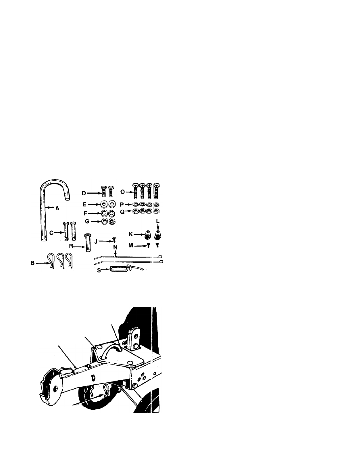
Hardware Pack
FIGURE 1.
Tailpiece
Frame
Long End
of “U” Clevis
Pin (A)
-Contents of Hardware Pack: (See Figure 1)
A (1) U-Clevis Pin
B (3) Hairpin Clips
C (2) Clevis Pins 3/8" Diameter
D (2) Hex Bolts 3/8-16 x 1" Long
E (2) Belleville Washers 3/8" I.D.
F (2) Lock Washers 3/8" I.D.
G (2) Hex Nuts 3/8-16 Thread
J (1) Phillips Head Self-Tapping Screw
K (1) Left Hand Cable Hold-Down (Black)
L (1) Right Hand Cable Hold-Down (Brown)
M (2) Self-Tapping Screws
N (2) Cable Ties
O (4) Carriage Bolts 5/16-18 x 1з^" Long
P (4) Lock Washers 5/16" I.D.
Q (4) Hex Nuts 5/16-18 Thread
R (1) Clevis Pin 1/2" Diameter
S (1) Spring Pin
TAILPIECE INSTALLATION
Slide the tailpiece into the chassis. Secure with “U”-
-clevis pin (A) and hairpin clip (B). See figure 2.
NOTE
Hairpin Clip (B)
FIGURE 2.
The U-clevis pin which secures the ,
tailpiece can be set for two different
methods of operation. Refer to “Swinging
Tailpiece/Depth Stake” section on
page 10.
Depth Stake
FIGURE 3.
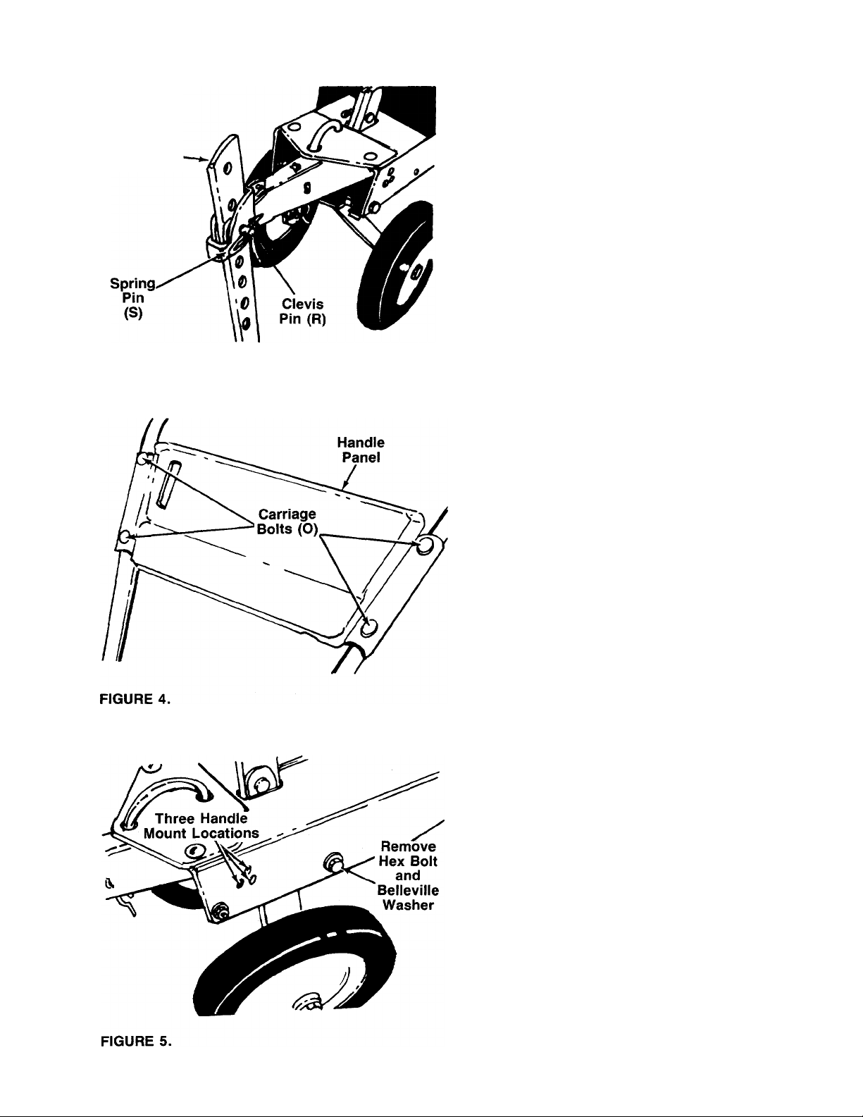
DEPTH STAKE INSTALLATION
Slide the depth stake into the tailpiece to desired depth.
Pointed end of depth stake should face forward. Secure
-with clevis pin (R) and spring pin (S). See figure 3.
ASSEMBLY OF HANDLES
1. Place the handle panel in position on the right and
left hand handles so the tower ends of the handles
bend toward the inside.
2. Secure with carriage bolts (O), lock washers (P)
------
-and hex nuts (Q), finger tight only. See figure 4.
3. Remove hex bolt and belleville washer from each
side of frame as shown in figure 5.
4. Place the handle panel assembly in position
against the frame.
5. Start the hex bolt and belleville washer (removed
in step 3) by hand in the bottom hole in handle.
6. Select height position for the handle by lining up
one of the holes in the handle with desired hole
-----
in frame. See figure 5.
Hex Bolt
FIGURE 6.
A
B
c
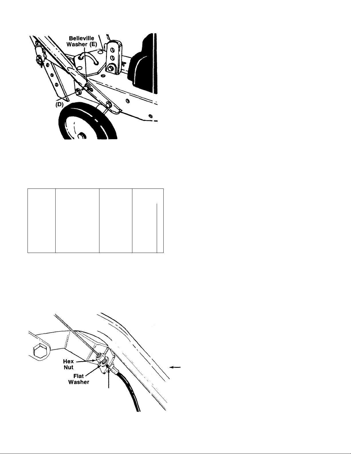
7. Place belleville washer (E) on hex bolt (D), and in
sert hex bolt through handle and frame. Secure
with lock washer (F) and hex nut (G) on inside of
-----
frame. See figure 6.
8. Tighten securely all nuts and bolts used to assem
ble the handle.
THROTTLE CONTROL ASSEMBLY
The throttle control is already attached to the engine.
Assemble the throttle control to the handle panel as
follows (be careful not to kink the cable).
1. Route the throttle control cable between the han
dle mounting brackets. Hold the throttle control
assembly beneath the handle panel. Turn the con
trol sideways and insert the lever up through the
wide portion of the slot on the handle panel. See
-------figure 7A.
2. After the end of the lever is through the slot, turn
and then tip the control forward as shown in figure
7B.
FIGURE 7.
FIGURE 8.
Slot in
Cable Bracket
Sci
(•)
V
The lever must be all the way to the
back of the control housing as shown
in figure 7B.
Push the control back into the slot in the handle
3.
panel and press in place. See figure 7C. Be cer
tain the control is locked securely into the slot.
Secure the throttle control to the handle panel
4.
using Phillips head self-tapping screw (J). See
figure 7D.
ATTACHING THE CLUTCH CONTROL CABLES
The clutch control cables, already attached to the idler
brackets, are labeled FORWARD and REVERSE. The
left hand cable hold-down is black and is marked with
an “L.” The right hand cable hold-down is brown and
is marked with an “R.”
1. Attach the forward clutch cable to the left handle
as follows (be careful not to kink the cable),
a. Remove one hex nut and flat washer from the
end of the casing on the forward clutch cable.
Slip the wire through the slot on the cable
bracket on the left handle. Push the end of the
casing up through the cable bracket. Rethread
the hex nut on the end of the cable. Do not
tighten at this time. See figure 8.
■I^NOTE
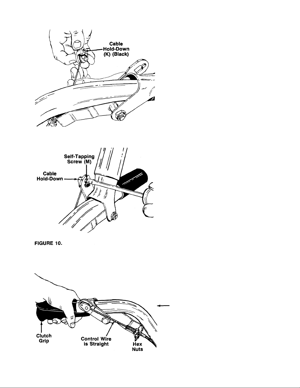
FIGURE 9.
b. Hook the barrel end of the cable into the left
hand cable hold-down (K) (black). Slide the
—cable around in the slot as shown in figure 9.
c. Puli the cable upwards to obtain slack, lift clutch
grip, and insert the left hand cable hold-down
into the ieft hand clutch grip. Secure with self-
—tapping screw (M). See figure 10.
d. With the clutch lever released (in the “up” posi
tion), adjust the bottom nut at the cable bracket
so there is only a slight amount of slack in the
control wire. Tighten the upper nut against the
bracket. Squeeze the clutch lever against the
handle. The control wire should now be straight,
see figure 11.
FIGURE 11.
NOTE
Do not overtighten control wire. Too much
tension may cause it to break.
2. Attach the reverse ciutch cable to the right handle
in the same manner, using the right hand cable
hold-down (L) (brown).
3. Secure the control cables to the handles using
cable ties (N).
4. Trim excess ends of cable ties.
WARNING
Ai
The forward and reverse clutch cable
adjustment must be checked before
the unit is operated as instructed in
the Final Adjustment section on page 8.
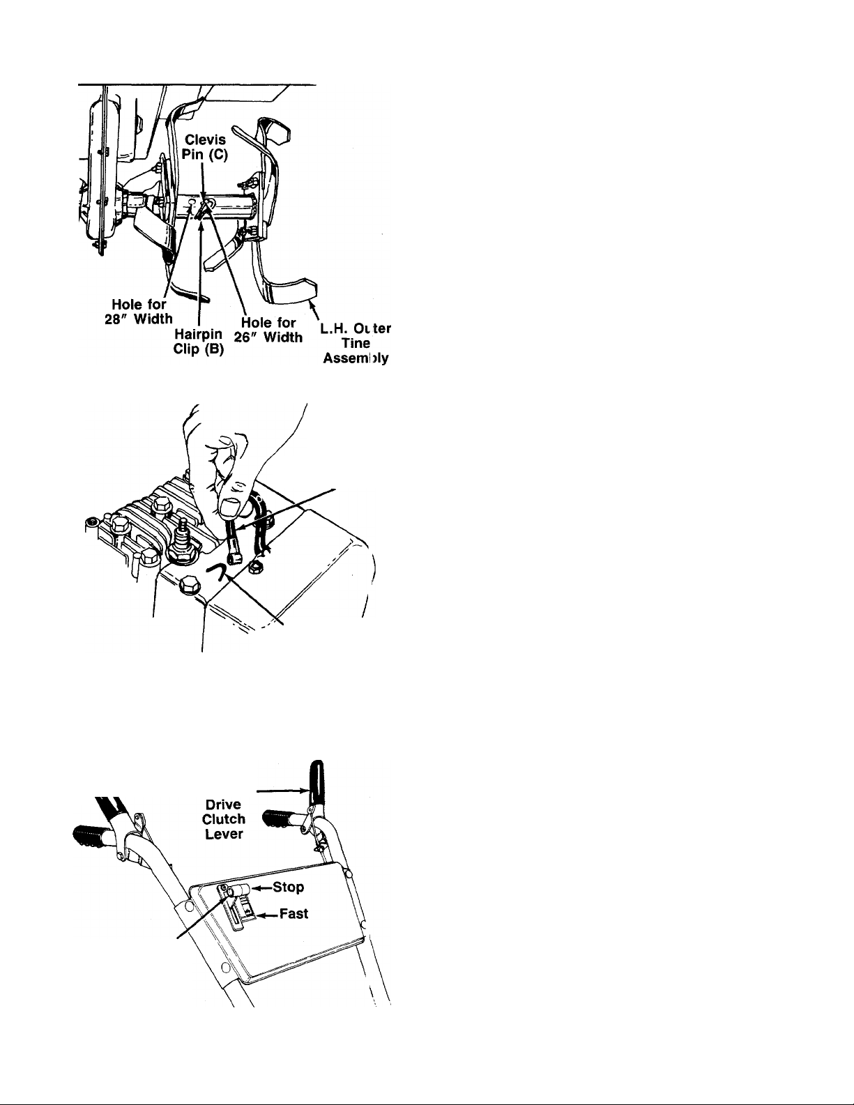
FIGURE 12.
FIGURE 13.
Spark Plug
Wire
{ “V” Slot
on Engine
TINE INSTALLATION
The inner tine assemblies are installed in their correct
position at the factory. Check to be certain the tine
assemblies are on the tine shaft so that the sharp edge
enters the soil first. See figure 12.
1. Align one of the holes in the tine assembly with the
hole in the tine shaft. Using the end hole on the
tine assembly will give a tilling width of 28". Using
the second hole will give a tilling width of 26". See
------
figure 12.
2. Secure with clevis pin (C) and hairpin clip (B).
3. Secure the other tine assembly in the same
manner.
NOTE
Make certain tines are installed so
that the sharp edge of the tines wiii
enter the soii first when in forward
drive.
FINAL CLUTCH ADJUSTMENT
To check the forward and reverse clutch cable adjust
ment, proceed as follows.
1. Disconnect the spark plug wire from the spark plug
to prevent accidental starting. Secure the end of
spark plug wire in the “V” slot on the engine. See
------
figure 13.
2. With both clutch grips released (neutral position),
pull the starter rope several times. The tines
shouid not turn. If they turn forward, loosen the
hex nut below the cable bracket on the left han
dle a few turns. Tighten the hex nuts above the
bracket. If they turn in reverse, adjust the hex nuts
at the cable bracket on the right handle in the
same manner.
CONTROLS
Reverse Drive
‘Clutch Lever
Throttle
Control
FIGURE 14.
Forward-
THROTTLE CONTROL
The throttle control lever is located on the handle panel.
It controls the engine speed and stops the engine. See
figure 14.
FORWARD DRIVE CLUTCH LEVER
The forward drive clutch lever is located on the left han
dle. See figure 14. Squeezing the lever against the han
dle engages the forward tine drive. Release the lever
to stop the forward motion.
REVERSE DRIVE CLUTCH LEVER
The reverse drive clutch lever is located on the right
handle. See figure 14. Squeezing the lever against the
handle moves the tines in reverse. Release the lever
to stop the reverse drive.
■I^NOTE
Never engage both the forward and
reverse drive at the same time, or the
engine will stall.
 Loading...