

Page 1

Model No. 219-360
%a/i A/eu/'
10 CENTS
MTD
ROTARY TILLER
WARRANTY
For one year from date of purchase, MTD Products Inc will replace for the original purchaser, free
of charge, F.O.B. factory or authorized service firm, any part or parts found to be defective in material
or workmanship. All transportation charges on parts submitted for replacement under this warranty must
be paid by the purchaser. This warranty does not include replacement of parts which become inoperative
through misuse, excessive use, accident, neglect, improper maintenance or alterations by unauthorized
persons. This warranty does not include the engine, motor, battery, battery charger or any component
parts thereof. For service on these units refer to the applicable manufacturer’s warranty.
The above warranty will apply only to the original owner and will be effective only if the warranty
card has been properly processed. It will not apply where the unit has been used commercially.
Warranty service is available through your local authorized service dealer or distributor. UNDER NO
CIRCUMSTANCES WILL THE RETURN OF A COMPLETE UNIT BE ACCEPTED BY THE FACTORY
UNLESS PRIOR WRITTEN PERMISSION HAS BEEN EXTENDED.
SAFETY RULES
Your rotary tiller is a precision built machine designed to take the work out of gardening and other
related chores. It can be used for seed bed preparation, tilling, cultivating, furrowing, composting and
mulching. Like any other piece of power equipment, it requires a certain amount of care and mainte
nance. In return for this, it will give a maximum of service and efficiency. Read these instructions
carefully before assembling or operating your tiller. Through proper care and operation, you will obtain
long, efficient service and trouble free operation.
1. Your tiller is a precision piece of power equip
ment. Exercise extreme caution at all times.
2. Do not attempt to start engine with the clutch
control in engaged or “Forward” position.
3. Stand clear of tines when starting engine. Never
stand in front of, or work on tines while the
engine is running.
4. NEVER place hands or feet in the vicinity of
the tines while the engine is running.
5. Always stop engine when tiller is not in actual
use.
6. Always disconnect spark plug wire during re
pairs or refueling operations.
7. Do not fill gas tank while engine is running.
Do not spill gasoline on hot engine.
MTU PRODUCTS I3STC • 5389 west 130th ST. • P.O. box 2741 • CLEVELAND, OHIO 44111
FORM NO. 770-1884A
Page 2
■n
o
s
Z
o
0
1
CO
00
03
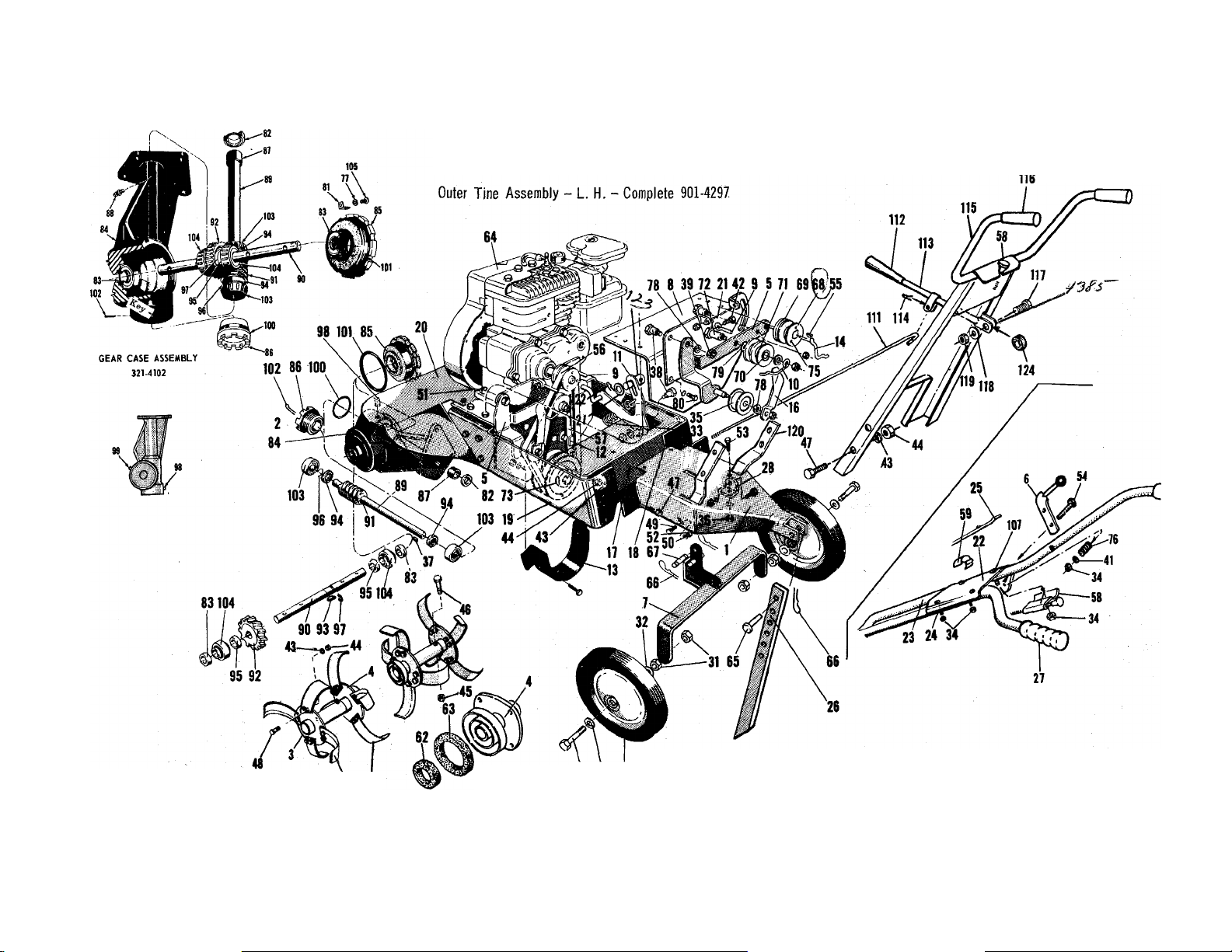
Inner Tine Assembly - R. H. - Complete 901-4296
Inner Tine Assembly - L. H. - Complete 901-4295
Outer Tine Assembly - R. H. - Complete 901-4298
60 61
30 32 29
219-360
Page 3

PARTS LIST FOR MODEL MTD 219-360
Ulus.
No.
10
11
12
13 321-4162 Belt Guard
14
15 310-8271
16 310-4147 Belt Clip
17 395-4399 Rear Frame
18
19 395-4397
20
21
22 395-4243 Handle Panel
23 310-4246 Handle - R.H.
24
25
26
27 305-1166
28 310-4124
29 501-8929 Wheel Assembly
30 710-275
31 712-384
32 736-108 '
33
34 712-107
35
36 712-372
37
38 710-373
39 712-430 Hex Elastic Stop Nut 3/8—16 thd.
40 712-123 Hex Nut 5/16-24 thd.*
41
42 710-258
43 736-169
44 712-798 Hex Nut 3/8-16 thd.*
45 712-116
46
47
48 710-183
49 710-451
50 736-119
51
52
53 710-118
54
55
56
57 754-103
58 746-122
59 746-111
60 742-113
61
62
63 736-125
64
65
66
Part
No.
1 395-4330
Tailpiece Assembly
DESCRIPTION
( ) - No. Required Per Assembly
2 321-4102-1 Gear Case Assembly (Complete)
3
395-4265
4
395-4266
5
310-4168 Reverse Pivot Bracket Assembly
6
310-4164
7
321-4172
8
395-4170
Outer Tine Adapter Assembly
Inner Tine Adapter Assembly
Control Handle Assembly 72
Wheel Hanger Assembly
Engine Mounting Plate
9 310-4149 Belt Retainer
310-4151
310-4158
Belt Retainer
Control Lever
310-4148 Belt Clip
310-4155
Control Rod
Adjustment Tube
395-4398
Side Frame — R.H,
Side Frame — L.H.
312-4395
Dust Shield
310-4167 Adjustment Plate
310-4247 Handle - L.H.
711-394 Control Rod
321-4328
Depth Bar
Grip
Handle Mounting Bracket
Hex Hd. Cap Sew. 13x5 Ig.*
Hex Centerlock Nut Vi—13 thd.*
Washer 33/64 I.D.*
732-376
Spring—Tension
Hex Centerlock Nut ^^--20 thd.*
756-370 Idler Bearing Assembly
Hex Centerlock Nut 5/16—18 thd.*
714-314 Key — Hi Pro #606
Shoulder Bolt
736-463 Washer 9/32 I.D.*
Hex Hd. Cap Sew. 20x5/8 Ig.*
Lockwasher 3/8 Screw*
Hex Elastic Stop Nut 3/8—24 thd. *
710-113
Hex Hd. Cap Sew. 3/8-24x1-5/8 Ig
Heat Treated *
710-253 Hex Hd. Cap Sew. 3/8—l6x 1 Ig. *
Hex Hd. Cap Sew. 3/8-16x1-1/8 Ig.*
Carriage Bolt 5/16—18x3/4 Ig. *
Lockwasher 5/16 Screw *
710-442 Hex Hd. Cap Sew. 5/16—18x 1-Vi Ig.*
712-267
Hex Nut 5/16-18 thd.*
Hex Hd. Cap Sew. 5/16—18x3/4 Ig.*
710-136
714-105
754-121
■Hex Hd. Cap Sew. V4—20 x 1-3/4 Ig. *
Key - Square 3/16 x 3/16 x 1 Ig. *
“V” Belt 1/2 X 31.8 - Gates *
“V” Belt 1/2 X 27 - Gates *
Control - Throttle (complete)
Cable Clip
Tine - L.H.
742-110
736-124
Tine - R.H.
Dust Pad
Dust Pad
711-231 Clevis Pin
714-106
Locking Pin
■Illus.
No.
67
68
69
70
71 756-112
Part
No.
711-137
716-104
717-109
748-111
DESCRIPTION
( ) - No. Required Per Assembly
Support Pin
Pulley
Reverse Drive Wheel
Bronze Sleeve Bearing
Pulley — 2 Stage
711-138 Shoulder Screw
756-108 Pulley - 2 Stage
73
74 710-765
Set Screw — Allen 5/1624 x V4 Ig.
Not Shown
710-185
75
732-958
76
736-147
77
736-300 Washer 3/8 I.D.*
78
736-466
79
80 710-122
310-4101 Locking Clamp +
81
721-100
82
721-101
83
719-100 Housing — Gear Case +
84
719-lOlR
85
86 719-102
748-106
87
737-108
88
89
711-132
90 711-133
91 717-104
92 717-105
Allen Socket Head Cap Screw 10-32 x 1 Ig.*
Spring — Compression
Lockwasher #10 Screw*
Washer 17/32 I.D. *
Hex Hd. Cap Sew. 5/16—24x 1 Ig.*
Oil Seal — Garlock #76x6113 +
Oil Seal - Garlock #78x7510 +
Bearing Adjustment Cap - 1”
Bearing Adjustment Cap - 3/4” +
Bronze Sleeve Bearing +
Alemite Drive Fitting #1992-B1 * +
Worm Shaft - 3/4” +
Tine Shaft - 1” +
Worm +
Worm Wheel +
93 714-103 Key - Woodruff #91 * +
711-130
94
711-131 Spacer - 1” +
95
716-101
96
716-102
97
98 737-102
737-103
99
735-100
100
735-101
101
714-474
102
741-107
103
741-108
104
710-125 Rd. Hd. Mach. Sew. 10-24x1/2 Ig. * +
105
710-256
107
109 710-252
Spacer - 3/4” +
Snap Ring - Tru Arc #5l00'75 * +
Snap Ring - Tru Arc #5100-175 * +
Pipe Plug - Special Breather Type +
Pipe Plug - Square Head 3/8 thread * +
“O” Ring 2-1/8 X 2-3/8 X 1/8 +
”0” Ring 3-5/8 X 3-7/8 X 1/8 +
Cotter Pin 1/8 Dia. x 3/4 Ig. * +
Roller Bearing - Timken 3/4" +
Roller Bearing - Timken 1” +
Carriage Bolt Vi—20 x 1-W Ig. *
Hex Hd. Cap Sew. Vi—20x3/4 Ig. *
110 712-324 Hex Stop Nut V4—20 thread *
111
711-402 Control Rod
720-143
112
310-4392
113
114 714-115
395-4381
115
116 305-1166
710-106
117
Knob
Handle Rod Assembly
Cotter Pin 1/8x1 Ig. *
Handle Assembly
Grip
Hex Head Cab Screw
Vi—20xlVi Ig. *
736-195
118
712-324
119
120 395-4386
736-204
121
714-507
122
123 711-392
124 736-155
Flat Washer
Hex Elastic Stop Nut Vi-20 thd.
Brackets — Panel
Flat Washer *
Cotter Pin 3/32 X 3/4 Ig. *
Ferrule
Rubber Washer
901-4295 Inner Tine Assembly - L.H. - Complete
901-4296 Inner Tine Assembly - R.H. - Complete
901-4297 Outer Tine Assembly-L.H. - Complete
901-4298
727-112
Outer Tine Assembly-R. H. - Complete
Lubricant 5 oz. (Gear Case)
* For faster service obtain standard nuts, bolts and washers
locally. If these items cannot be obtained locally, order by
part number and size as shown on parts list.
FORM NO.770-1884C
Page 4

ASSEMBLY
Your rotary tiller is shipped complete in a single carton.
The tines, wheels, handles, controls and depth bar are
to be assembled. This is done in the manner described
below.
TINES - Mount tines on tine shaft as shown. Tines
must be mounted with the cutting edges facing the front.
The tiller will not operate properly unless the sharpened
surface of the tines enter the soil first. Secure tines in
position on the tine shaft with cap screws (46), and nuts
(45). NOTE: Dust pads (62 & 63) are provided in screw
pack. These must be assembled as shown.
WHEELS - Insert axle bolts(30) into wheel hubs. Secure
with locknuts (31) tightened only enough to allow free
movement of the wheels (29). Attach wheel and axle
assemblies to tiller with support and locking pins.
HANDLE - Assemble the handle brackets (120) to the
handle (115) with hex head screw (47), lockwashers,
(43) and hex nuts (44). Do not tighten. Place the handle
brackets (120) in the tail piece slots. Fasten the lower
hole in the handle brackets to the frame with a carriage
bolt 5/16-18 X 3/4 Ig. (49), lockwasher (52) and hex nut
(50). Tighten all screws and nuts.
CLUTCH CONTROL LEVER ASSEMBLY
LOCKOUT LEVER - Place the hex head screw
1/4-20x1 1/4 (117) through the hole in the tab below the
slot in the handle panel from the right hand side. As
semble in this order: Rubber washer, lock out rod (rod
bracket to the front), steel washer and lock nut. Tighten
until rubber washer compresses slightly.
CLUTCH CONTROL ASSEMBLY. Screw the ferrule
(123) on the threaded end of the lock out rod (111) until
about 1/2” of the threads show. Insert the ferrule
through the control lever (11), fasten with flat washer
(121) and cotter hairpin (122). Put the lockout handle
in the neutral position. Insert the lockout rod in the
bracket on the lockout lever and secure with a cotter
hairpin, through the center of the bracket. Adjust the
ferrule so both belts are slack when the lockout lever is
in the neutral position.
THROTTLE - To assemble the throttle push the black
plastic knob in all the way then pull it out until the
detent ball clicks into the second notch. The knob will
be pulled out approximately 1-3/8” when in the second
notch. In this position the spring lockwasher and hex
nut will slide past the detent ball. Place the conduit
through the slot in the handle panel (see fig 2) and push
the unit (see fig 3) in until it seats as shown (see fig 1).
Secure with the spring lockwasher and hex nut.
OPTIONAL HANDLE (SMALL HANDLE PANEL)
HANDLES - Insert handles (23 & 24) into slots in tail
piece assembly (1). NOTE: The handles are left (24)
and right (23) and must be positioned accordingly.
Secure handles in position with cap screws (47) through
the upper mounting holes and the tailpiece bracket (28).
Fasten with lockwashers (43) and nuts (44). Do not
tighten.
HANDLE PANEL & CLUTCH CONTROL - Assemble
handle panel (22) to handles as shown. Secure top
portion with carriage bolts (107) and locknuts (34).
Assemble control handle assembly (6) to panel with cap
screw (54), spring (76), washer (41) and locknut (34) as
shown. Attach adjustment tube (15) to control rod (25).
Insert formed end of control rod into control pivot lever
(11) from left side. Fasten upper end to control handle
assembly with cap screw (109) and locknut (110). Move
throttle control knob out enough to allow face washer to
be loosened. Position control (58) into slot in end of
large panel. Tighten face washer. Fasten control cable
to handle with cable clip (59).
DEPTH BAR - Attach depth bar (26) in desired position
with clevis pin (65) and locking pin (66).
GRIPS - Assemble grips (27) to handlte bars.
OPERATION
1. Check tiller tines for proper installation. With
throttle contrg^lever set on “Stop” position and
the clutch control handle set in “Forward” posi
tion, slowly crank engine to determine direction of
tine rotation. Be sure all tines are mounted so the
sharpened edges enter the soil first.
2. Check all nuts and bolts for proper tightness. This
is especially important during the initial operation
period. Make this same check periodically there
after.
3. Check throttle control for proper setting. If choke
control on engine is not fully extended when jthe
throttle control lever is on “Choke” position, reset
as shown in ADJUSTMENT instructions.
4. Check gear case for proper lubricant level. With tiller
on a level surface, lubricant level should be up to the
front pipe plug opening. This can be checked by
removing front pipe plug. Maintain correct lubricant
level with Molilube SAE 140 Gear Oil or equivalent.
The gear case holds five (5) ounces of lubricant.
FORM NO.770-1884D
Page 5

TILLER DRIVE MECHANISM
REVERSE DRIVE WHEEL
717-109
PULLEY - ENGINE
756-104
REVERSE DRIVE WHEEL
717-109
LOCKNUT
712-430
BELT RETAINER
310-4149
PULLEY-ENGINE
756-104
BELT RETAINER
310-4151
ADJUSTMENT
712-267
736-119
710-118
IDLER PULLEY.
756-370
BELT 1/2 X 31.8
754-121
ALLEN CAP SCREW
710-185
TWO STAGE REVERSE PULLEY
BELT RETAINER
310-4149
LOCKNUT
712-430
BELT 1/2 X 27
754-103
ADJUSTMENT
HOLES
BELT CLIP
310-4148
CONTROL LEVER
// 310-4158
//
•4 TENSION SPRING
CONTROL ROD
711-213
TWO STAGE PULLEY
756-108
LOWER BELT GUARD
394-4162
FORM NO.770-1884G
Page 6

SERVICE NOTES
DRIVE BELT SLIPS
1. Lubricate contact surface between pivot bracket
assembly and adjustment plate.
2. Check pivot bracket assembly locknuts for excessive
tightness.
3. Check control rod for improper assembly. If adjust
ment tube is attached to lower end instead of upper
end, it may bind on control lever and prevent full
use of tension spring.
4. If spring tension is still insufficient, adjust to
another mounting hole on control lever.
5. Some measure of belt adjustment may be made by
loosening the mounting bolts on the adjustment plate
and moving as needed. This adjustment is usually
used for reverse drive wheel adjustments.
6. Large pulley and belt may be rubbing on lower belt
guard,
7. Idler pulley must operate freely.
8. Belt guard or clips must not touch the belt when it
is tightened.
REVERSE DRIVE WHEEL ADJUSTMENT
1. Reverse drive wheel should line up with its matching
pulley. If it does not, loosen pulley to which revers
ing drive wheel is attached and align as needed.
When reassembling, tighten set screw securely.
2. Matching pulley for reversing drive wheel can be
mounted one way only. The reversing drive wheel
must operate in the deeper groove.
3. If belt retainer touches engine pulley after adjust
ment, move to outside mounting or bend away as
needed.
4. Additional reverse adjustment may be made by
loosening the mounting bolts on the adjustment plate
and moving as needed.
5. Reverse should operate only when control handle
assembly is held in reverse position. Adjust control
rod for proper operating position.
NOTE: If belts are excessively stretched, replacement
will be necessary.
ADJUSTMENTS - (see fig. 4)
To Check:
Remove Air Cleaner. Move Throttle
Assembly to CHOKE position. The
carburetor choke should then be
closed. Move the Throttle to STOP.
Control lever on carburetor should
then make good contact with stop
switch to short out ignition.
To Adjust:
Place Throttle on equipment in FAST
(high speed) position. Lever “C” on
carburetor should be just touching
choke arm at “D”. To adjust, loosen
casing clamp screw “A” on blower
housing. Move control casing ”B”
forward or backward until correct
position is obtained. Tighten screw
“A”. Recheck above operation and
replace Air Cleaner.
NOTE: This instruction manual covers various models and all'accessories
shown do not necessarily apply to your model tiller.
MT-D PRODUCTS INC extends its warranty only on
the tiller. If repairs or service is needed on the engine,
please contact your nearest, authorized engine service
Find It Fast
In Th*
'Yellow Pages'
outlet. Check tiie “Yellow Pages” of your telephone
book under “Engines — Gasoline.”
FORM NO.770-1884H
PRINTED IN U.S.A.
Page 7

5. Check fuel tank. Clean, fresh, regular gasoline
should be used at all times.
6. Check engine crankcase for proper oil level. The
engine is shipped without oil in the crankcase. Be
sure to fill crankcase before starting engine. Be
sure crankcase is FULL.
NOTE: The engine is warranted separately by the
engine manufacturer. For warranty service contact the
engine manufacturer or their local authorized service
station. All important information pertaining to care and
operation is included in the engine manual.
STARTING YOUR TILLER
1. Be sure clutch control handle is in “Neutral”
position.
2. Move throttle control lever to “Choke” position.
3. After cranking the engine several times, or as the
engine fires, move the throttle control lever to run
position.
4. Use “Choke” as needed to keep engine operating
during warm-up period.
5. Adjust throttle control lever for desired operating
speed.
6. To stop engine, move throttle control lever to “Stop”
position. Keep throttle control lever in “Stop”
position at all times when tiller is not in use.
NOTE: A brief break in period is essential to insure
maximum engine life. This consists of running the
engine at half speed for a period of time required to
use one tank of gasoline. This is necessary on the
initial run only. It is also recommended that the oil be
changed after fiyj^ (5) hours of operation. This allows
for the removal of impurities which may have accumu
lated during the break in period. Subsequent oil changes
should be made as stated in the engine manual. Always
check oil before using your tiller. Be sure crankcase
is full.
OPERATING INSTRUCTIONS
For your own convenience and safety, observe all safety
suggestions shown on the front cover. Your tiller is not
a toy, it is a precision piece of power equipment. Treat
it as such.
It is important to recognize the fact that the forward and
penetrating action of the rotary tiller is obtained from
the rotating action of the tines in the soil. The depth
bar acts as a brake for the tiller and controls the depth
and speed at which the machine will operate. By lower
ing the setting of the depth bar, the forward speed of the
machine is reduced and the working depth of the tines
is increased. Raising the setting of the depth bar
increases the forward speed and reduces the working
depth. When soil conditions are severe and several
passes must be made over a certain area, the depth bar
setting should be lowered each time a pass is made.
Further control of tilling depth and travel speed can be
obtained by variation of pressure on the handles. A
downward pressure on the handles will increase the
working depth and reduce the forward speed. An upward
pressure on the handles will reduce the working depth
and increase the forward speed. The type of soil and
working conditions will determine the actual s etting of
of the depth bar and the handle pressure required.
1. Tine engagement and forward travel is achieved by
moving the clutch control handle to “Forward” posi
tion. Tine rotation and forward motion are stopped by
moving the clutch control handle to “Neutral” posi
tion. Reverse tine action and reverse travel motion
can be maintained by HOLDING the clutch control
handle in “Reverse” position. Releasing the handle
stops reverse operation automatically.
2. The throttle control lever adjusts the engine speed.
It also gives fingertip control of the carburetor choke
and magneto stop switch. With the throttle control
knob pushed completely forward, and carburetor is in
“Choke” position. Pulling the knob out slightly
releases the carburetor from “Choke” and adjusts
the engine speed to “Fast.” Pulling the knob further
out reduces the engine speed to “Slow.”
When the knob is pulled completely out, the magneto
stop switch grounds out the spark and stops the
engine.
3. With the depth bar raised out of operation, self
propelled transporting of the tiller is easily achieved.
With no pressure on the handles and the throttle
control set for “Slow” engine speed, move the
clutch control handle to the rear position and let
the tiller gently propel itself.
ADJUSTMENTS
‘BELTS - Belt slack is taken up by a spring loaded
idler pulley. Because of this, belt adjustment is not
required.
CLUTCH - No adjustment in clutch linkage is required.
This is done automatically by the spring loaded idler.
"O” RING - If oil leakage at the bearing ca£ should
occur, take up on the “o” ring of the gear case may
be needed. This is aocomplished by removing the
locking clamp and turning the bearing adjustment cap
clockwise enough to correct. Move adjustment cap back
one notch and replace locking clamp.
THROTTLE - If adjustment becomes necessary, the
throttle control wire assembly can be reset as follows:
1. Loosen, but do not remove, screw securing throttle
control wire assembly at engine.
2. Move throttle control knob to “Choke” position.
3. Move lever, to which control wire is fastened at
engine, to full choke position and retighten screw to
secure throttle control wire assembly.
FORM N0.770-1884E
Page 8

HANDLES - The position of the handles may be ad
justed by removing and moving carriage bolts in the
lower mounting holes. Adjustment should be made for
the most convenient operating height.
WHEELS - Wheel positions may be varied to give
adjustment of handle height. Various wheel positions
also give variations of the leverage and weight distri
bution over the tines. Wheels should be set to suit the
local soil conditions and the operator’s convenience.
Wheel hanger may be reversed to give variation of
leverage and weight distribution.
TINES - The standard width of cut is 26”. Because of
the various types of work the tiller may be put to, varia
tion in the tilling width may be necessary. This can be
accomplished in a number of ways.
1. Standard tine arrangement. 26”
2. Remove outer tine assemblies (complete). 12”
3. Remove outer tines from outer tine assemblies. 20”
Tines may be interchanged with opposite sides.
4. Add tine extensions to standard arrangement. 40”
NOTE: When adjusting tines, be sure the cutting edges
enter the soil first.
MAINTENANCE AND LUBRICATION
ENGINE - Service engine in accordance with the en
gine manufacturer’s owner’s guide. NOTE: To drain oil,
remove oil filler plug and tip tiller on its side. Drain
oil while the engine is warm. See engine mattual for
filling instructions. ,
GEAR CASE - Proper lubricant level should be up to
the front pipe plug. Check with tiller on a level surface.
Add lubricant through the vented pipe plug hole. Add
enough to bring level up to front plug hole. Use
Mobilube SAE 140 Gear Oil or equivalent. Gear case
should be maintained with five (5) ounces of lubricant.
Lubricate the upper bushing in the gear case with a
small amount of grease. Do not over lubricate as any
excess will enter the gear case proper. Use a high
pressure gun grease.
THROTTLE - Periodically lubricate throttle control
lever and throttle control wire assembly with a few
drops of light oil (SAE 10 or 20) for ease of operation.
REPLACING TILLER GEAR CASE OIL SEALS
1. Drain lubricant.
2. Remove tine assemblies.
3. Remove bearing adjustment cap.
4. Remove bearings, worm wheel, and tine shaft. Do
not remove bearing races. *
5. Remove oil seals from gear case and bearing ad
justment cap.
6. Remove all burrs from holes in tine shaft.
7. Dip oil seals in lubricant and then insert one in
gear case, and one in bearing adjustment cap.
8. Wipe line shaft clean of filings and lubricate before
assembling with bearings and worm wheel in gear
case.
9. Replace bearing adjustment cap. CAUTION: Do not
damage oil seals. The open flanges face to the out
side of the gear case.
10. Tighten bearing adjustment cap enough to seal
“O” rings.
11. Lock bearing adjustment cap in position with lock
ing clamp.
12. Replace tines and add lubricant.
BELTS - “V” Belts and pulley assemblies are acces
sible at the rear of the tiller. The belts are changed as
described below.
To remove large belt —
1. Place clutch control handle in “Neutral” position.
2. Remove lower belt guard (13).
3. Loosen (Do not remove) belt clip (16) and remove
belt. (56)
To remove small belt —
1. Remove large belt as described.
2. Place clutch control handle in “Forward” position.
3. Loosen belt retainer (10) and remove belt (57).
To replace small belt —
1. Position belt on pulleys. Be sure belt is in proper
pulley grooves.
2. Move clutch control handle to “Neutral” position.
3. Move belt retainer (10) into position against reverse
pivot bracket and tighten. Do not tighten excessive
ly. Pulley (71) should have approximately 1/16”
end play.
To replace large belt —
1. Position belt on pulley (35).
2. Position belt on pulley (68).
3. Position belt on pulley (73).
4. Replace and tighten lower guard (13).
5. Place clutch control handle in “Forward” position.
6. Tighten belt clip (16). CAUTION: Upper part of belt
clip should clear belt by 1/8”.
GENERAL - Check periodically all nuts and bolts,
loose nuts and bolts can cause permanent damage to
your unit. Keep all nuts and bolts securely listened.
STORAGE - The following steps should be taken to
prepare your tiller for storage.
1. Clean tiller thoroughly and lubricate as described
in the preceding instructions.
2. Coat tilling tines with grease to prevent rusting.
3. Prepare engine for storage in accordance with en
gine manufacturer’s owner’s guide.
4. Block tiller legs to raise tires clear of floor. Be
sure tiller is level.
5. Store in a dry clean area.
ATTACHMENTS
EXTENSION TINES - This attachment is available to
increase your tilling width up to 40”. Extension tines
are easily installed and removed. Order under part
number 299-165.
FURROW OPENER - This attachment is easily install
ed on the depth bar of your tiller. It can be used for
either furrowing or hilling operations. These attach
ments are available through your local dealer.
For wide (2” x .43” depth bar,) order furrow opener 299-179
FORM NO.770-1884F
 Loading...