

Page 1

10 CENTS
Model No. 219-100
%u/iMe4jU'
ROTARY TILLER
WARRANTY
For one year from date of purchase, MTD Products Inc, will replace for the original pur
chaser, free of charge, F.O.B. factory or authorized service firm, any part or parts found to be
defective in material or workmanship. All transportation charges on parts submitted for replace
ment under this warranty must be paid by the purchaser. This warranty does not include replace
ment of parts which become inoperative through misuse, excessive use, accident, neglect, im
proper maintenance or alterations by‘unauthorized persons. This warranty does not include the
engine, motor, battery, battery charger or any component parts thereof. For service on these
units refer to the applicable manufacturer’s warranty.
The above warranty will apply only to the original owner and will be effective only if the
warranty card has been properly processed. It will not apply where the unit has been used com
mercially.
Warranty service is available through your local authorized service dealer or distributor.
UNDER NO CIRCUMSTANCES WILL THE RETURN OF A COMPLETE UNIT BE ACCEPT
ED BY THE FACTORY UNLESS PRIOR WRITTEN PERMISSION HAS BEEN EXTENDED.
AFETY RULE
Your rotary tiller is a precision built machine designed to take the work out of gardening and other
related chores. It can be used for seed bed preparation, tilling, cultivating, furrowing, composting and
mulching. Like any other piece of power equipment, it requires a certain amount of care and mainte
nance. In return for this, it will give a maximum of service and efficiency. Read these instructions
carefully before assembling or operating your tiller,
long, efficient service and trouble free operation.
1. Your tiller is a precision piece of power equip
ment. Exercise extreme caution at all times.
2. Do not attempt to start engine with the clutch
control in engaged or “Forward” position.
3. Stand clear of tines vyhen starting engine. Never
stand in front of, or work on tines while the
engine is running.
MANUFACTURED BY
3VITD FK.ODXJOTS IKTO • 5389 west i30th sT. • p.o. box 2741
Through proper care and operation, you will cbtain
4. NEVER place hands or feet in the vicinity of
the tines while the engine is running.
5. Always stop engine when tiller is not in actual
use.
6. Always disconnect spark plug wire during re
pairs or refueling operations.
7. Do not fill gas tank while engine is running.
Do not spill gasoline on hot engine.
CLEVELAND, OHIO 44111
FORM NO. 770-1881A
Page 2
o
X
2
Z
o
OPTIONAL HANDLE
22
. TINE SHAFT EXTENSION ASSEMBLY
MODEL 299-162
(Optional equipment available through
your Dealer.)
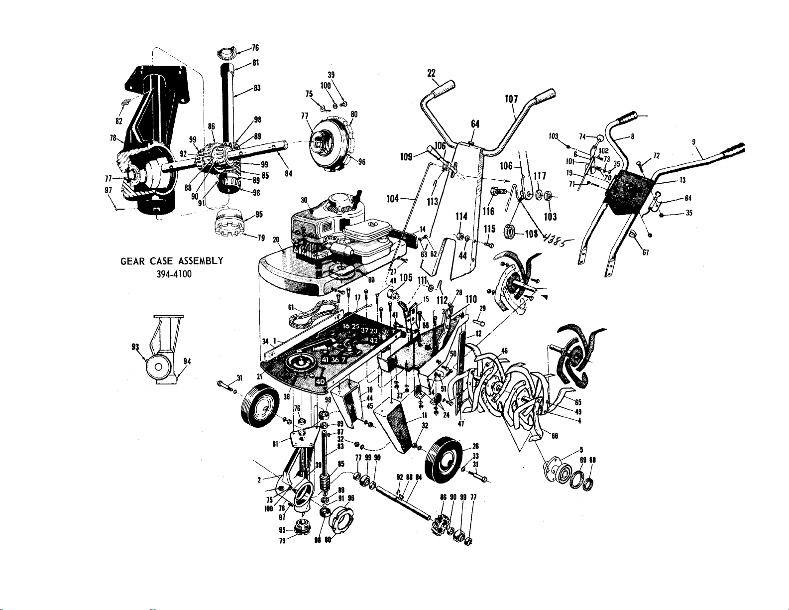
394-4100 GEAR CASE ASSEMBLY - COMPLETE
901-4291 TINE ASS’Y-COMPLETE-L.H. INNER
901-4292 TINE ASS’Y-COMPLETE-R.H. INNER
901-4293 TINE ASS’Y-COMPLETE-L.H. OUTER
901-4294 TINE ASS’Y-COMPLETE-R.H. OUTER
93
219-100
Page 3

Ulus
No.
Part
No.
Descripti on
( )- No. req'd. per Assy.
Ulus.
No.
TILLER MODEL 219-100
Part
No.
Description
( )-No. req’d. per Assy.
Illus.
No.
Part
No.
"V'
Description ^
()-No. req’d per Assy.
351-4105 Mounting Plate Assembly
1
321-4100
2
351-4329
3
321-4134
4
321-4138
5
310-4164 Control Handle Assembly 46 712-116
6
7 312-4187
312-4244 Handle - R. H.
8
9
312-4245
351-4110
10
351-4109
11
321-4328
12
13 351-4243
14 310-4126
Gear Case Assembly (complete)
Tailpiece Assembly
Outer Tine Adapter Assembly 44
Inner Tine Adapter Assembly
Idler Bracket Assembly
Handle - L. H.
Leg - R. H.
Leg - L.H.
Depth Bar
Handle Panel
Inspection Plate 53 710-158
41
710-373
736-300
42
43 712-430
736-169 Lockwasher 3/8 Screw *
45 712-798
47
710-113
710-253
48
49 710-183
710-451 Carriage Bolt 5/16-18x3/4 Lg, *
50
51 736-119 Lockwasher 5/16 Screw *
712-123
52
15 310-4156 Control Lever Engine Mounting Bolt - not shown
16 312-4161
17
310-4152
19 711-393
20 312-4103
21 310-7439
305-1166
22
310-7353 Belt Clip
23
24 310-4124
310-4195
25
26 501-8009
27 710-259
732-194
28
29
711-231
30
31
710-182 Hex Hd. Cap Sew. 1/2-13x3 Lg. •
712-384 Hex Centerlock Nut 1/2-13 thd. * 70
32
33 736-108
34
732-376
35
712-107
36
756-370
37
712-372
o
31
3
z
o
38 756-926
39 710-125
40
710-421
Belt Guard
Control Rod - lower
Control Rod - upper
Engine Bed
54
55 710-118
56
710-606
58
Anchor Spring Pin 59
Grip
60
61 754-103
Handle Mounting Bracket
Belt Clip
62 710-202 Hex Hd.Self-tapping Sew, 10-32xl/2Lg.
63 736-147
Wheel Assembly 64
Hex Hd. Cap Sew. 5/16-18x5/8 Lg. •
65
Spring Pin 66
Clevis Pin
Engine
67
68
69 736-125
Washer 33/64 I. D. *
71
Spring - Tension 72
Hex Centerlock Nut 1/4-20 thd. * 73 736-463
Idler Bearing Assembly
Hex Centerlock Nut 5/16 - 18 thd. *
74 305-7891 Ball Knob +
75
Pulley 4-1/2 X 3/4 76 721-100 Oil Seal - Garlock #76x6113 **
Rd. Hd. Mach. Sew. 10-24x 1/2 lg.* 77
Set Sew. Allen 5/16 - 18x 1/4 Lg.'* 78
For faster service, obtain standard nuts, bolts, and washers locally. If these items
cannot be obtained locally, order by part number and size as shown on parts list.
» *
Part of Gear Case Assembly (complete) 394-4100.
Part of Control Handle Assembly 310-4164.
Shoulder Bolt
Washer 3/8 I. D. *
Hex Elastic Stop Nut 3/8 - 16 thd.
Hex Nut 3/8 - 16 thd. *
Hex Elastic Stop Nut 3/8-24 thd.
Hex Hd. Cap Sew. 3/8-24 x 1-5/8 Lg. *
Hex Hd. Cap Sew, 3/8-16x1 Lg. *
Hex Hd, Cap Sew. 3/8-16 x 1-1/8 Lg. *
Hex Nut 5/16 - 24 thd, *
Engine Mounting Nut - not shown
Hex Hd. Cap Sew. 5/16-24x1-1/4 lg. *
712-267
Hex Nut 5/16 - 18 thd. *
Hex Hd. Cap Sew. 5/16 - 18 x 3/4 Lg, *
Hex Hd. Cap Sew, 1/4-26x 1-1/2Lg.*
714-105 Key-Sq. 3A6x 3/16x1 *
756-107
Pulley 2-1/2 X 7/8
710-765 Set Sew. - Allen 5/16 - 24x 1/4 Lg. *
"V" Belt 1/2x27 - Gates *
Lockwasher #10 Screw *
746-J7J
-Control - Throttle (complete)
742-105 Tine - L.H.
742-106
746-111
Tine R. H.
Cable Clip
736-124 Dust Pad
Dust Pad
732-958 Spring - Compression
710-136
Hex Hd. Cap Sew. 1/4-20x 1-3/4 Lg.*
710-256 Carriage Bolt 1/4-20x1-1/2 Lg. *
Washer 9/32 I.D. *
310-4101 Locking Clamp **
721-101
Oil Seal - Garlock #78x7510 **
719-100 Housing - Gear Case **
321-4100 Gear Case Assembly (complete)
901-4291 Tine Assembly, complete - L.H. Inner
901-4292 Tina^ssembly, complete - R. H. Inner
901-4293 Tine Assembly, complete - L.H. Outer
901-4294 Tine Assembly, complete - R. H. Outer
727-112 Mobilube SAE 140 - 502
79 719-102
80 719-lOlR
748-106
81
737-108
82
TH-132
83
84 711-133
717-104
85
717-105 Worm Wheel **
86
714-314
87
88 714-103
89 711-130
711-131
90
716-101
91
716-102
92
93 737-102
94
737-103
95 735-100
735-101
96
714-474 Cotter Pin 1/8
97
741-107
98
99 741-108
736-147
100
310-8271
101
710-252
102
712-324
103
711-414 Control Rod
104
105 711-392
106 310-4392
351-4381
107
736-155 Rubber Washer
108
720-143
109
no 351-4386
736-204 Flat Washer
111
714-507
112
714-115 Cotter Pin 1/8x1 Lg. *
113
712-798 Hex Nut 3/8 - 16 thd. *
114
115
710-253
710-106
116
736-195
117
Bearing Adjustment Cap 3/4" ••
Bearing Adjustment Cap 1" **
Bronze Sleeve Bearing **
Alemite Drive Fitting-#1992-B1* **
Worm Shaft 3/4" •*
Tine Shaft 1" **
Worm **
Key - Hi Pro #606 * **
Key - Woodruff #91 * **
Spacer 3/4" *•
Spacer 1" ••
Snap Ring - TruArc #5100-75 **
Snap Ring - TruArc #5100-100 **
Pipe Plug - Special Breather Type **
Pipe Plug-Square Hd. 3/8 thd.** *
”0” Ring 2-1/8 X 2-3/8 X 1/8 **
"0" Ring 3-5/8 X3-7/8X 1/8 •*
Roller Bearing - Timken 3/4
Roller Bearing - Timken 1" **
Lockwasher #10 Screw * **
Adjustment Tube
Hex Hd, Cap Sew. l/4-20x3/4Lg. *
Hex Elastic Stop Nut 1/4 - 20 thd. *
Ferrule
Handle Rod Assembly
Handle Assembly
Knob
Brackets - Panel
Cotter Pin 3/32x3/4 Lg. *
Hex Hd. Cap Sew. 3/8 - 16x1 Lg.*
Hex Hd. Cap Sew. 1/4 - 2-x l-l/4Lg. *
Flat Washer
Page 4

ASSEMBLY - ONE PIECE HANDLE
Your rotary tiller is shipped complete in a single carton.
The tines, wheels, handles, controls and depth bar are to be
assembled. This is done in the manner described below.
TINES — Mount tines on tine shaft as shown. Tines must
be mounted with the cutting edges facing the front. The
tiller will not operate properly unless the sharpened sur
face of the tines enter the soil first. Secure tines in posi
tion on tine shaft with cap screws (47), and nuts (46).
NOTE: Dust pads (68 & 69) are provided in screw pack.
WHEELS: Insert axle bolts (31) into wheel hubs. Se
cure with locknuts (32) tightened only enough to allow
free movement of the wheels (26). Attach wheel and axle
assemblies to outside of tiller legs (10 & 11). Fasten with
locknuts (32) as shown.
HANDLE — Assemble the handle brackets (110) to the
handle (107) with hex head screw (115), lockwashers (44)
and hex nuts (114). Do not tighten. Place the handle (110)
in the tail piece slots. Fasten the lower hole in the handle
brackets to the frame with a carriage bolt 5/16—18 x Ig.
(50), lockwasher (51) and hex nut (54). Tighten all screws
and nuts.
CLUTCH CONTROL LEVER ASSEMBLY
Lockout Lever. Place the hex head screw i^-20 x 1^
(116) through the hole in the tab below the slot in the
handle panel from the right hand side. Assemble in this
order: Rubber washer, lock out rod (rod bracket to the
front), steel washer and lock nut. Tighten until rubber
washer compresses slightly.
Clutch control assembly. Screw the ferrule (105) on
the threaded end of the lock out rod (104) until about
Vz” of the threads show. Insert the ferrule through the
control lever (15), fasten with flat washer (111) and cotter
hairpin (113). Put the lockout handle in the neutral posi
tion. Insert the lockout rod in the bracket on the lockout
lever and secure with a cotter hairpin through the center of
the bracket. Adjust the ferrule so both belts are slack when
the lockout lever is in the neutral position.
DEPTH BAR — Attach depth bar (12) in desired posi
tion with clevis pin (29) and locking pin (28).
GRIPS — Assemble grips (22) to handle bars.
THROTTLE — To assemble the throttle push the black
plastic knob in all the way then pull it out until the detent
ball clicks into the second notch. The knob will be pulled
out approximately 1-3/8” when in the second notch. In
this position the spring lockwasher and hex nut will slide
past the detent ball. Place the conduit through the slot in
the handle panel (see fig 2) and push the unit (see fig 3) in
until it seats as shown see (fig 1). Secure with the spring
lockwasher and hex nut.
TINES — Mount tines on tine shaft as shown. Tines must
be mounted with the cutting edges facing the front. The
tiller will not operate properly unless the sharpened sur
face of the tines enter the soil first. Secure tines in posi
tion on tine shaft with cap screws (47), and nuts (46).
NOTE: Dust pads (68 & 69) are provided in screw pack.
These must be assembled as shown.
WHEELS — Insert axle bolts (31) into wheel hubs. Secure
with locknuts (32) tightened only enough to allow free
movement of the wheels (26). Attach wheel and axle as
semblies to outside of tiller legs (10 & 11). Fasten with
locknuts (32) as shown.
HANDLES — Insert handles (8 & 9) into slots in tailpiece
assembly (3). NOTE: The handles are left (9) and right
(8) and must be positioned accordingly. Secure handles in
position with cap screws (48) through the upper mounting
holes and the tailpiece bracket (24). Fasten with lockwashers (44) and nuts (45). Do not tighten. Select desired
handle position and secure lower part of handle with car
riage bolts (50), lockwashers (51) and nuts (54). Do not
tighten.
HANDLE PANEL —Position handle panel (13) over upper
handles and attach with carriage bolt (72) and locknuts
(35). The throttle control is mounted on the under side of
the left handle. Fasten with carriage bolt (72) through up
per handle hole and through the middle hole in the con
trol (64) mounting plate. Fasten control cable to handle
with cable clip (67). Tighten all nuts securely.
CLUTCH CONTROL — Insert lower end of control rod
(19) into control lever (15), mounting hole from left side.
Attach adjustment tube (101) to control rod and adjust
for approximate length. Attach tube to control handle
assembly (6) with cap screw (102) and stop nut (103).
Readjust if necessary.
DEPTH BAR — Attach depth bar (12) in desired position
with clevis pin (29) and locking pin (28).
GRIPS — Assemble grips (22) to handle bars.
ASSEMBLY - HANDLE WITH
SMALL HANDLE PANEL
Your rotary tiller is shipped complete in a single carton.
The times, wheels, handles, controls and depth bar are to
be assembled. This is done in the manner described below.
FORM NO. 770-1881 D
CHECK LIST BEFORE OPERATION
1. Check tiller tines for proper installation. With throttle
control lever set on “Stop” position and the clutch con
trol handle set in “Forward” position, slowly crank en
gine to determine direction of tine rotation. Be sure all
tines are mounted so the sharpened edges enter the soil
first.
Page 5

2. Check all nuts and bolts for proper tightness. This is
especially important during the initial operation period.
Make this same check periodically thereafter.
3. Check gear case for proper lubricant level. With tiller
on a level surface, lubricant level should be up to the
rear pipe plug opening. This can be checked by removing
rear pipe plug. Maintain correct lubricant level with
MobUube SAE 140 Gear Oil or equivalent. The gear case
holds five (5) ounces of lubricant.
4. Check fuel tank. Clean, fresh, regular gasoline should
be used at all times.
5. Check engine crankcase for proper oil level. The engine
is shipped without oil in the crankcase. Be sure to fill
crankcase before starting engine. Be sure crankcase
if FULL.
NOTE: The engine is warranted separately by the en^e
manufacturer. For warranty service contact the engine
manufacturer or their local authorized service station. All
important information pertaining to care and operation is
included in the engine manual.
STARTING YOUR TILLER
1. Be sure clutch control handle is in “Neutral” position.
2. Move throttle control lever to “Start” position.
3. After cranking the engine several times, or as the en
gine fires, move the throttle control lever to run posi
tion.
4. Adjust throttle control lever for desire operating
speed.
5. To stop engine, move throttle control lever to “Stop”
position. Keep throttle control lever in “Stop” position
at all times when tiller is not in use.
NOTE: A brief break in period is essential to insure maxi
mum engine life. This consists of running the engine at
half speed for a period of time required to use one tank of
gasoline. This is necessary on the initeal run only. It is also
recommended that the oil be changed after five (5) hours
of operation. This allows for the removal of impurities
which may have accumulated during the break in period.
Subsequent oil changes should be made as stated in the
engine manual. Always check oil before using your tiller.
Be sure crankcase is FULL’.
OPERATING INSTRUCTIONS
For your own convenience and safety, observe all safety
suggestions shown on the front cover. Your tiller is not a
toy, it is a precision piece of power equipment. Treat it as
such.
It is important to recognize the fact that the forward and
penetrating action of the rotary tiller is obtained from the
rotating action of the tines in the soil. The depth bar acts
as a brake for the tiller and controls the depth and speed at
which the machine will operate. By lowering the setting of
the depth bar, the forward speed of the machine is reduced
and the working depth of the tines is increased. Raising
the setting of the depth bar increases the forward speed and
reduces the working depth. When soil conditions are severe
and several passes must be made over a certain area, the
depth bar setting should be lowered each time a pass is
made. Further control of tilling depth and travel speed can
be obtained by variation of pressure on the handles. A
downward pressure on the handles will increase the work
ing depth and reduce the forward speed. An upward pres
sure on the handles will reduce the working depth and in
crease the forward speed. The type of soil and working con
ditions will determine the actual setting of the depth bar
and the handle pressure required.
1. Tine engagement and forward travel is achieved by mov
ing the clutch control handle to “Forward” position.
Tine rotation and forward motion are stopped by mov
ing the clutch control handle to “Neutral” position. Re
verse tine action and reverse travel motion can be main
tained by HOLDING the clutch control handle in “Re
verse” position. Releasing the handle stops reverse op
eration automatically.
2. The throttle control lever adjusts the engine speed. It
also gives finger tip control of the carburetor and
magneto stop switch. With the throttle control knob
pushed completely forward, the carburetor is in “Start”
position. Pulling the knob further out reduces the engine
speed to “Slow.”
When the knob is pulled completely out, the nagneto
stop switch grounds out the spark and stops the engine.
3. With the depth bar raised out of operation, self pro
pelled transporting of the tiller is easily achieved. With
no pressure on the handles and the throttle control set
for “Slow” engine speed, move the clutch control
handle to the forward position and let the tiller gently
propel itself.
ADJUSTMENTS
BELTS - Belt slack is taken up by a spring loaded idler pul
ley. Because of this, belt adjustment is not required.
CLUTCH - No adjustment in clutch linkage is required.
This is done automatically by the spring loaded idler.
NOTE: Belt and clutch adjustments can be made by mov
ing the engine bed. Loosen the four bolts which secure it
and move the engine bed forward or backward as required.
Adjusting the control rod will also effect belt and clutch
adjustment. These adjustments may be necessary if handle
position is changed.
"O" - If oil leakage at the bearing cap should occur, take
up on the “0” ring of the gear case may be needed. This is
accomplished by removing the locking clamp and turning
the bearing adjustment cap clockwise enough to correct.
Move adjustment cap back one notch and replace locking
clamp.
THROTTLE — If adjustment becomes necessary, the
throttle control wire asseihbly can be reset as follows:
1. Loosen, but do not reihove, screw securing throttle con
trol wire assembly at engine.
2. Move throttle control knob to “START” position.
3. Move lever, to which control wire is fastened at engine,
to full “OPEN” position and retighten screw to secure
throttle control wire assembly.
HANDLES - The position of the handles may be adjusted
by removing and moving carriage bolts in the lower mount
ing holes. Adjustment should be made for the most con
venient operating height.
WHEELS - Wheel positions may be varied to give further
adjustment of handle height. Various wheel positions also
give variations of the leverage and weight distribution over
the tines. Wheels should be set to suit the local soil condi
tions and the operator’s convenience.
FORM NO. 770-1881E
Page 6

TINES - The standard width of cut is 26”. Because of the
various types of work the tiller may be put to, variation in
the tilling widths may be necessary. This can be accom
plished in a number of ways.
1. Standard tine arrangement
............................................
26”
2. Remove outer tines from outer tine assemblies. Tines
may be interchanged with opposite sides
...................
20”
3. Add tine extensions to standard arrangement . . . 40”
NOTE: When adjusting tines, be sure the cutting edges
enter the soil first.
7. Reach through inspection hole and guide belt into posi
tion on engine pulley.
8. Check visually through inspection hole to make sure belt
is inside all belt guards and that pulleys are in proper al
ignment. A flashlight will help you make this check
quickly and easily.
9. Line up mounting holes and replace cap screws. Do not
tighten cap screws until all are in place. Replace inspec
tion plate.
MAINTENANCE AND LUBRICATION
ENGINE - Service engine in accordance with the engine
manufacturer’s owner’s guide. NOTE: To drain oil, remove
oil filter plug and tip filler on its side. Drain oU while the
engine is warm. See engine manual for filling instructions.
GEAR CASE - Proper lubricant level should be up to the
rear pipe plug. Check with tiller on a level surface. Add
enough to bring level up to rear pipe plug hole. Use Mobilube SAE 140 Gear Oil or equivalent. Gear case should be
maintained with five (5) ounces of lubricant.
Lubricate the upper bushing in the gear case with a small
amount of grease. Do not over lubricate as any excess will
enter the gear case proper. Use a high pressure gun grease.
THROTTLE - Periodically lubricate thorttle control lever
and throttle control wire assembly with a few drops of light
oil (SAE 10 or 20) forease of operation.
BELTS - Access to “V” belt and pulley assemblies is accom
plished by removing the engine and engine bed as described
below.
1. Remove four cap screws which secure engine bed to
mounting plate assembly. Remove engine and engine
bed. Do not kink control wire.
2. Loosen set screw in 41i” pulley. Remove pulley and
“V” belt. If belt clip on idler must be loosened to re
move belt, mark correct location of belt clip in relation
to idler before loosening. This can be done by scribing
the belt clip and the end of the weld bolt in idler with a
file. It is most important that this clip be reassembled in
the right position.
3. Position belt on 41^” pulley and replace on worm shaft.
Pulley must be mounted in position so that it will line
up with engine pulley when assembly is completed. The
correct position is that point at which the center of the
pulley is 1-1/8” above the mounting plate assembly.
Tighten set screw securely.
4. If belt clip has been loosened, Une up in original position
and tighten securely. Make sure belt is inside belt guards.
While holding the belt taut (grasp at extreme rear posi
tion), move clutch control handle to “Forward” and
“Neutral” position. If belt clip touches belt with handle
in either position, readjust position of clip.
5. Move clutch control handle to “Neutral” position. Re
move inspection plate from engine bed.
6. Replace engine bed and engine on mounting plate as
sembly. Do not kink control wire. Move engine bed and
engine as far forward as possible.
REPLACING TILLER GEAR CASE OIL SEALS
1. Drain lubricant.
2. Remove tine assemblies.
3. Remove bearing adjustment cap.
4. Remove bearings, worm wheel, and tine shaft. Do not re
move bearing races.
5. Remove oil seals from gear case and bearing adjustment
cap.
6. Remove all burrs from holes in tine shaft.
7. Dip oil seals in lubricant and then insert one in gear case
and one in bearing adjustment cap.
8. Wipe tine shaft clean of filings and lubricate before as
sembling with bearings and worm wheel in gear case.
9. Replace bearing adjustment cap.
CAUTION: Do not damage oil seals. The open flanges
face to the outside of the gear case.
10. Tighten bearing adjustment cap enough to seal “O”
rings.
11. Lock bearing adjustment cap in position with locking
clamp.
12. Replace tines and add lubricant.
GENERAL - Check periodically all nuts and bolts. Loose
nuts and bolts can cause permanent damage to your unit.
Keep all nuts and bolts securely tightened.
STORAGE — The following steps should be taken to pre
pare your tiller for storage:
1. Clean tiller thoroughly and lubricate as described in the
preceding instructions.
2. Coat tilling tines with grease to prevent rusting.
3. Prepare engine for storage in accordance with engine
manufacturer’s owner’s guide.
4. Block tiller legs to raise tires clear of floor. Be sure tiller
is level.
5. Store in a dry clean area.
ATTACHMENTS
EXTENSION TINES - This attachment is available to in
crease your tilling width up to 40”. Extension tines are
easily installed and removed. Order under part number
299-162.
FURROW OPENER - This attachment is easily installed on
the depth bar of your tiller. It can be used for either fur
rowing or hilling operations. These attachments are avail
able through your local dealer.
For wide (2” x .43”) depth bar, order furrow opener
299-179.
FORM NO. 770-1881 F
PRINTED IN U.S.A.
 Loading...